Proxim Wireless MESHMAXMP11R 802.11 a/b/g Access Point User Manual 2 MeshMAX5054Series User Guide
Proxim Wireless Corporation 802.11 a/b/g Access Point 2 MeshMAX5054Series User Guide
Contents
- 1. Users Manual 1
- 2. Users Manual 3
- 3. Users Manual 4
- 4. Users Manual 2 part 1
- 5. Users Manual 2 part 2
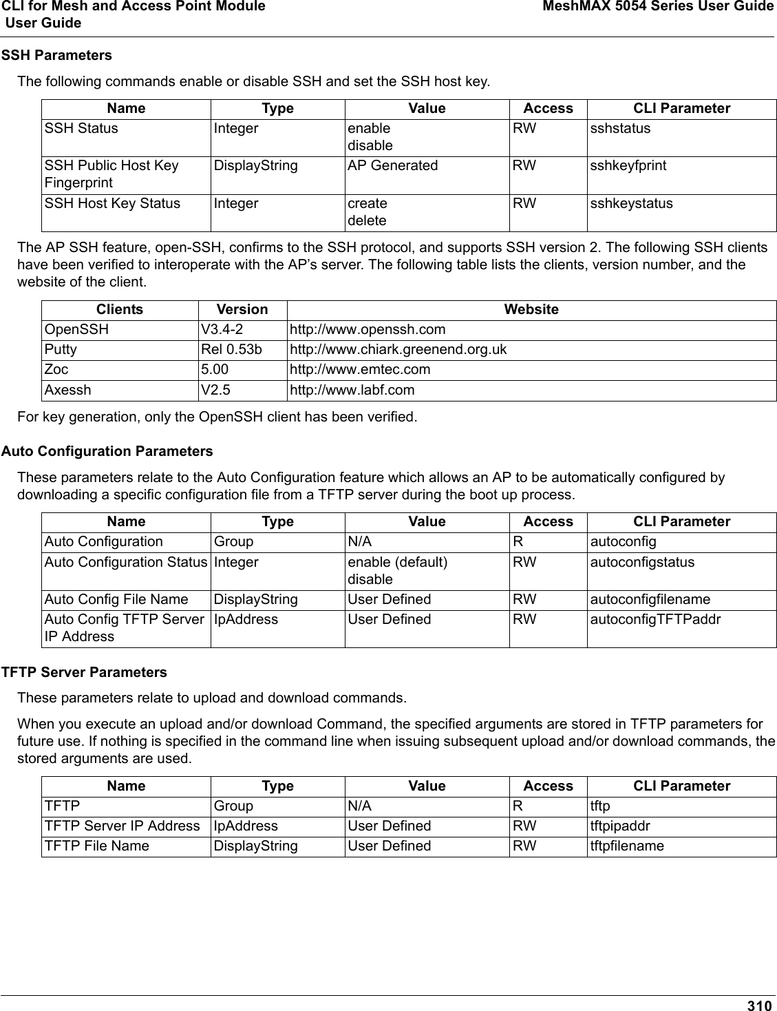
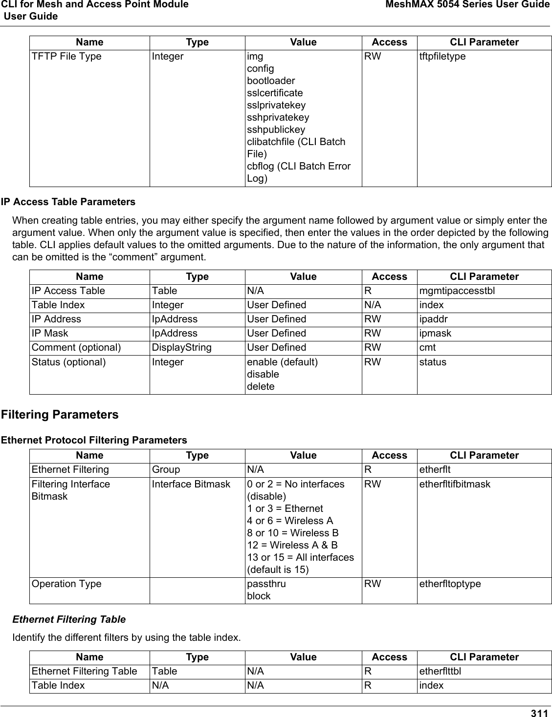
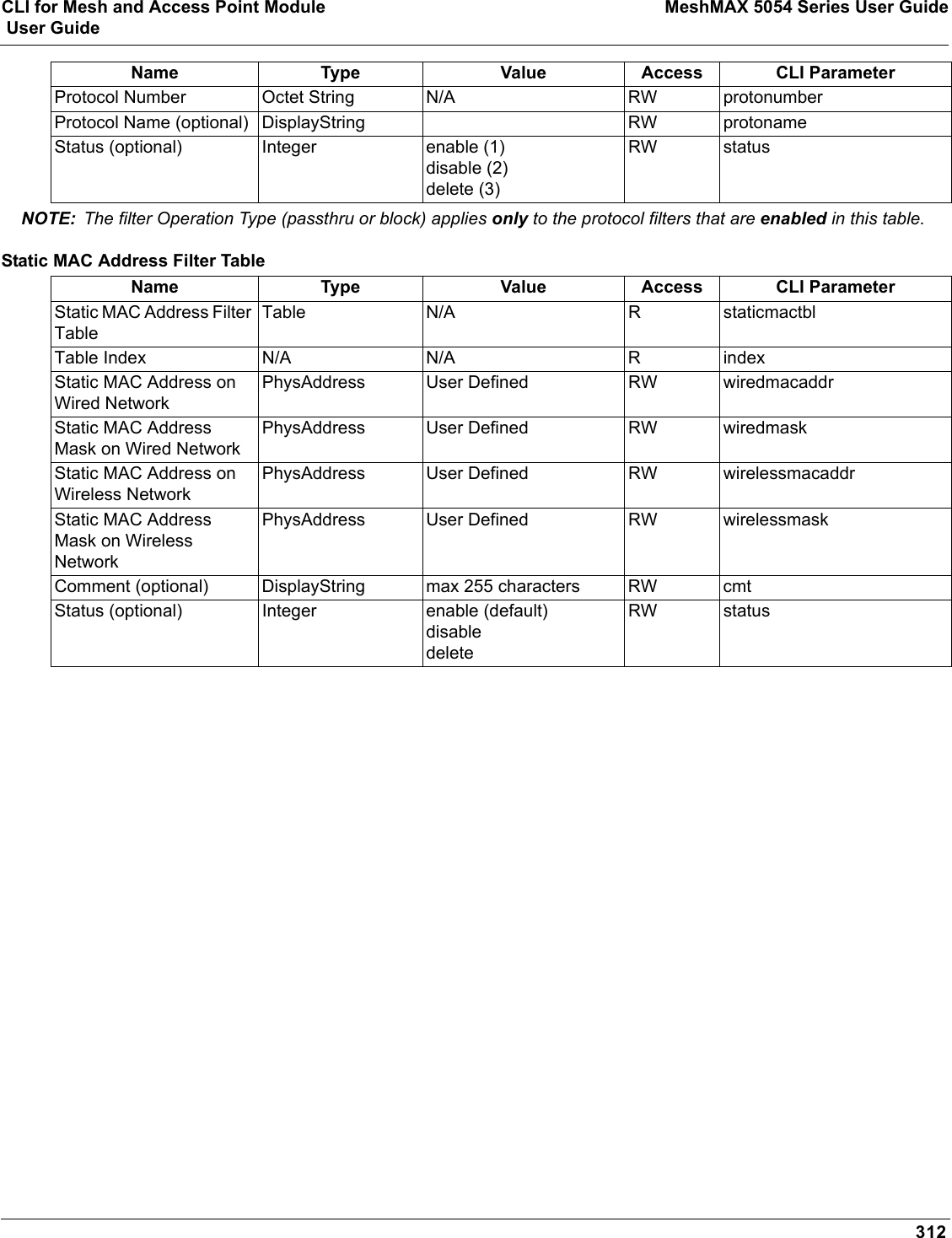
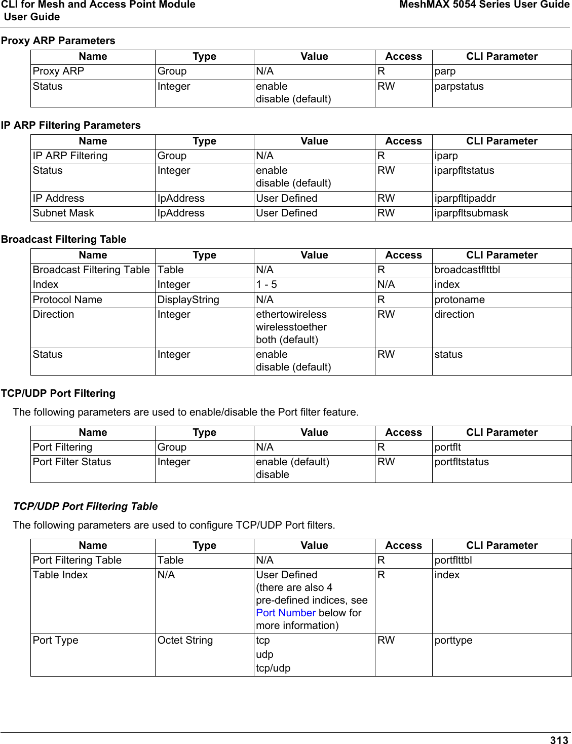
Users Manual 2 part 2
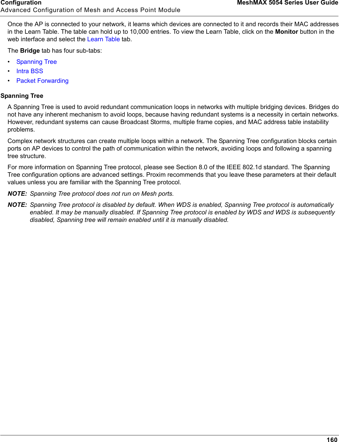
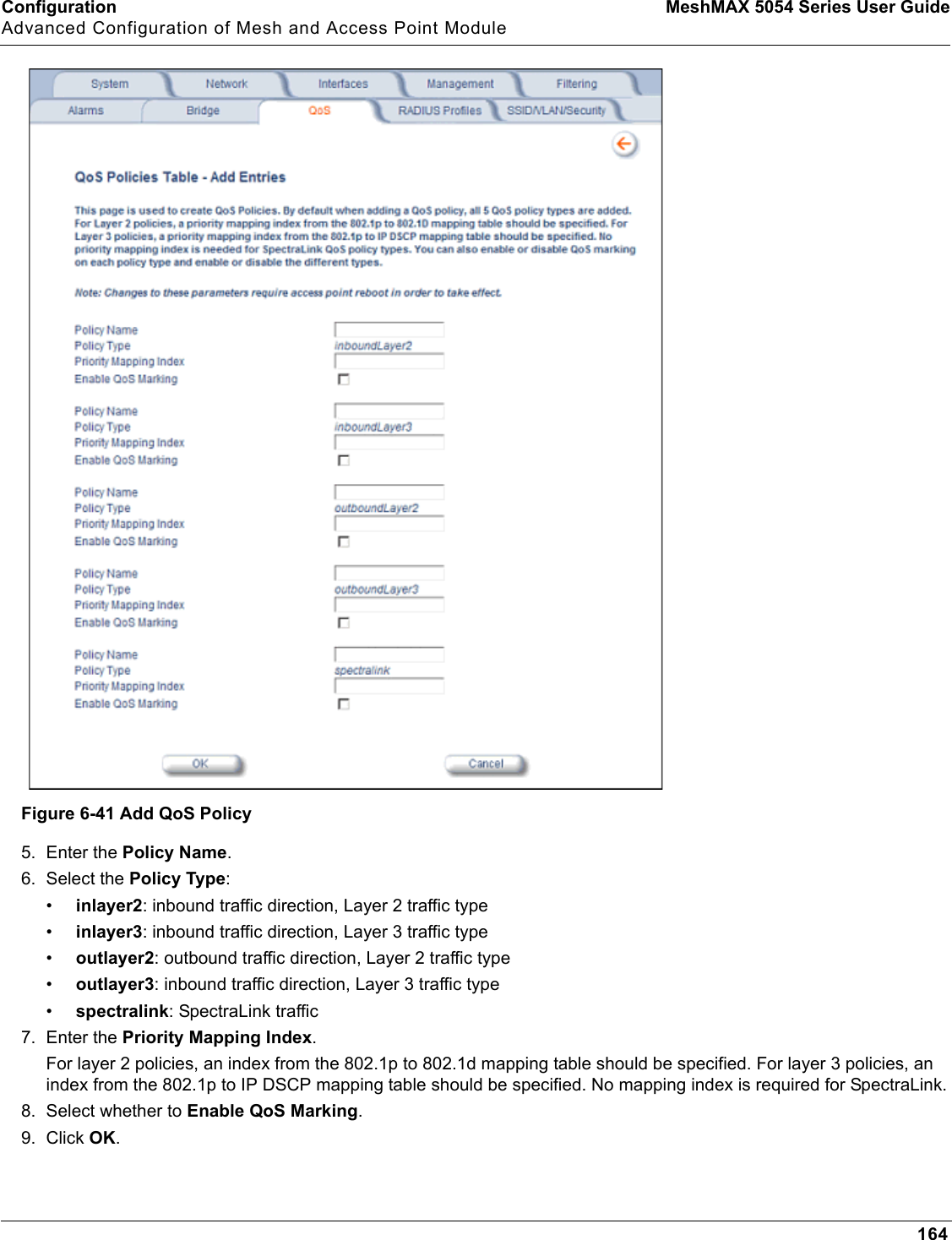
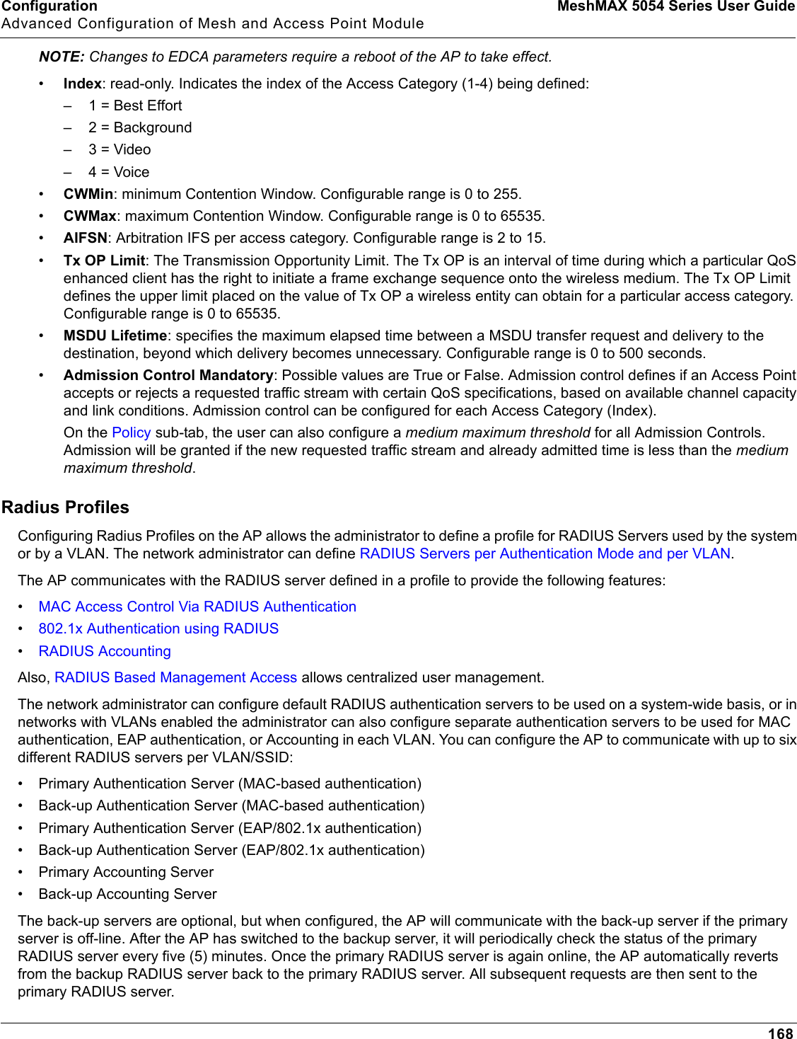
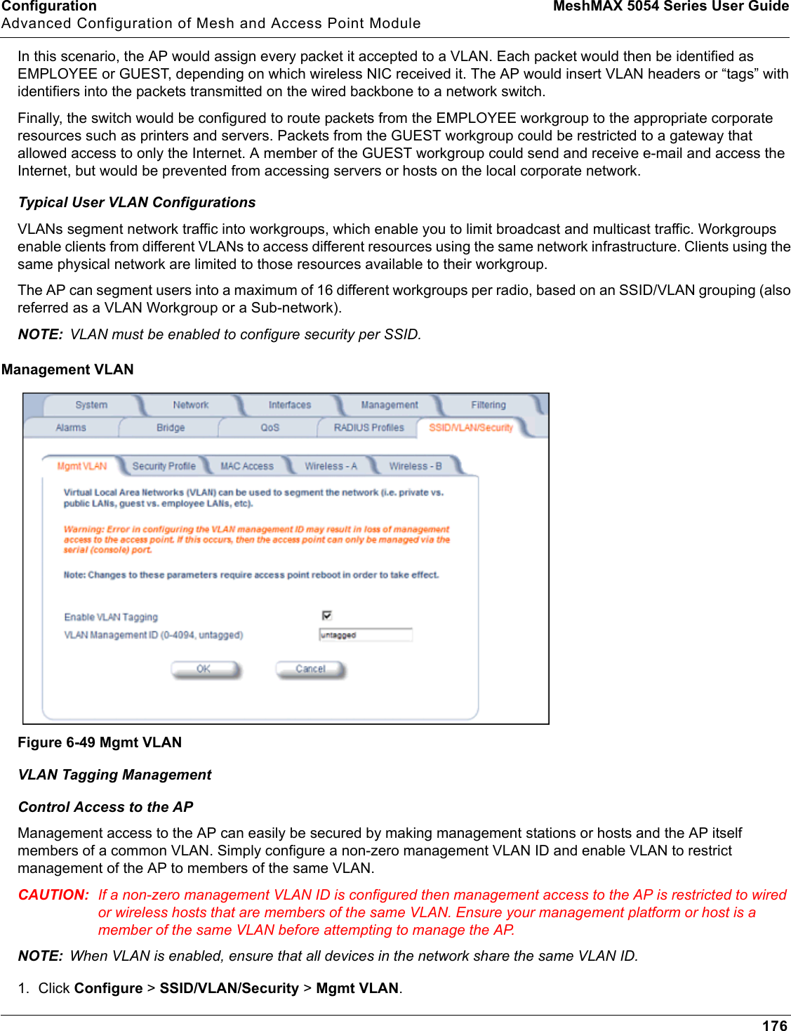
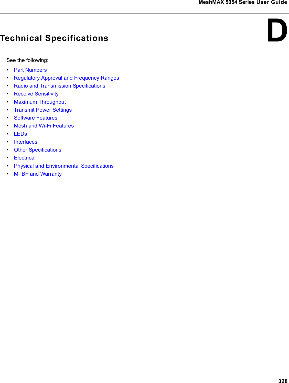
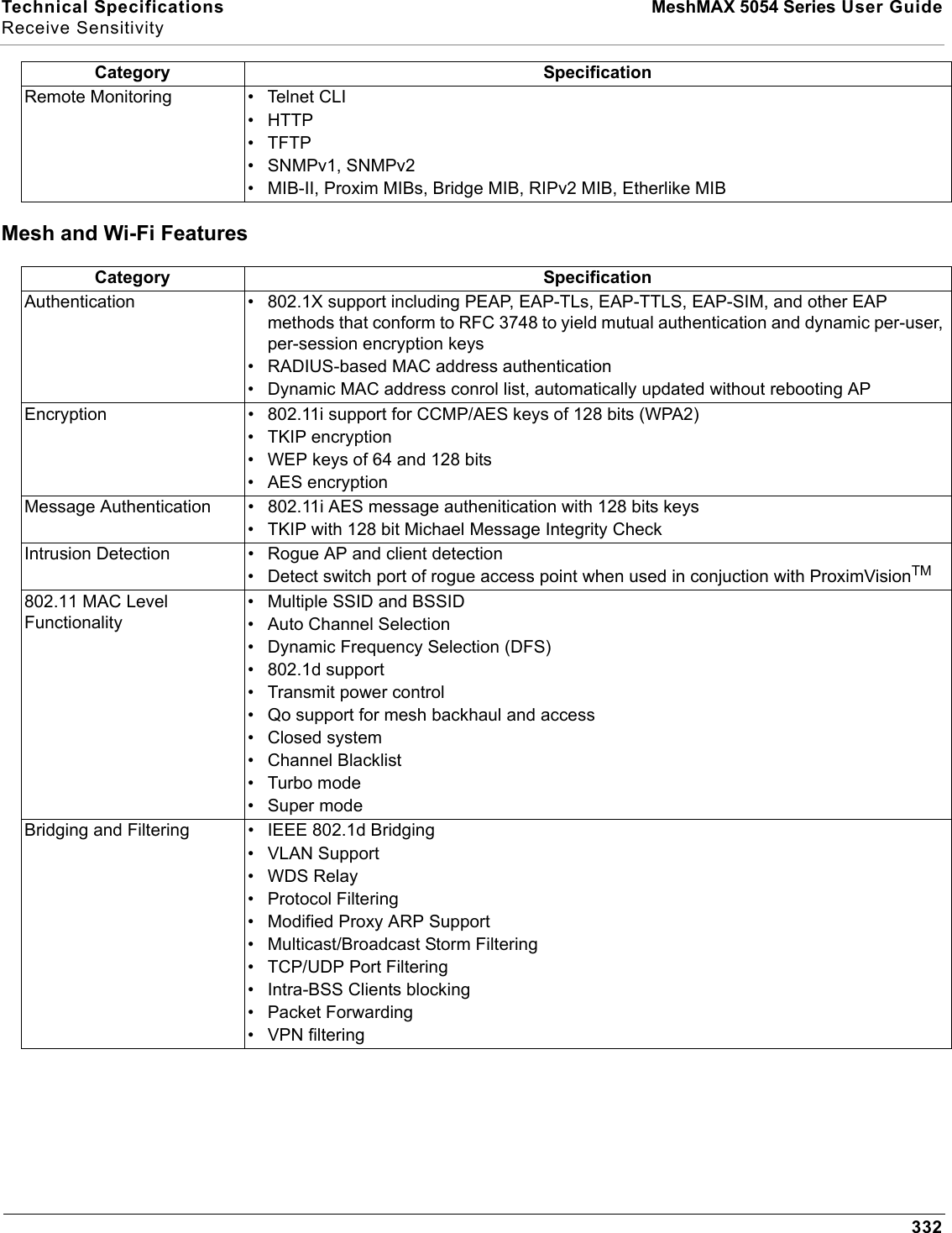
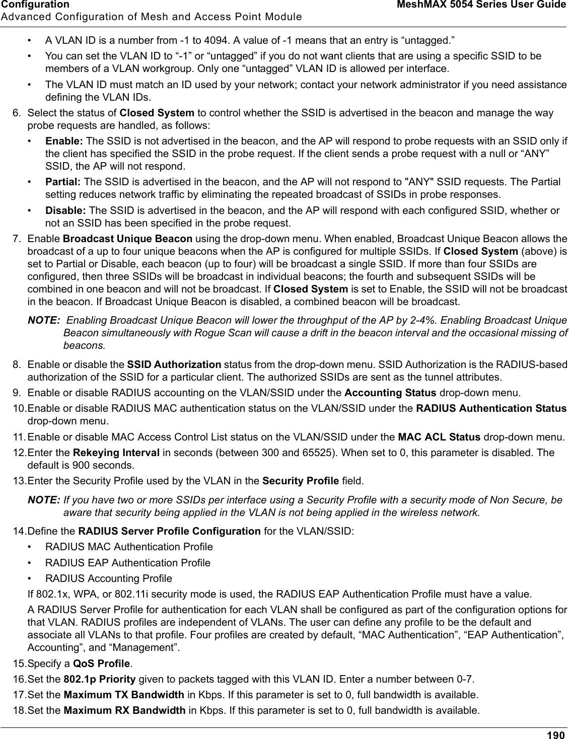
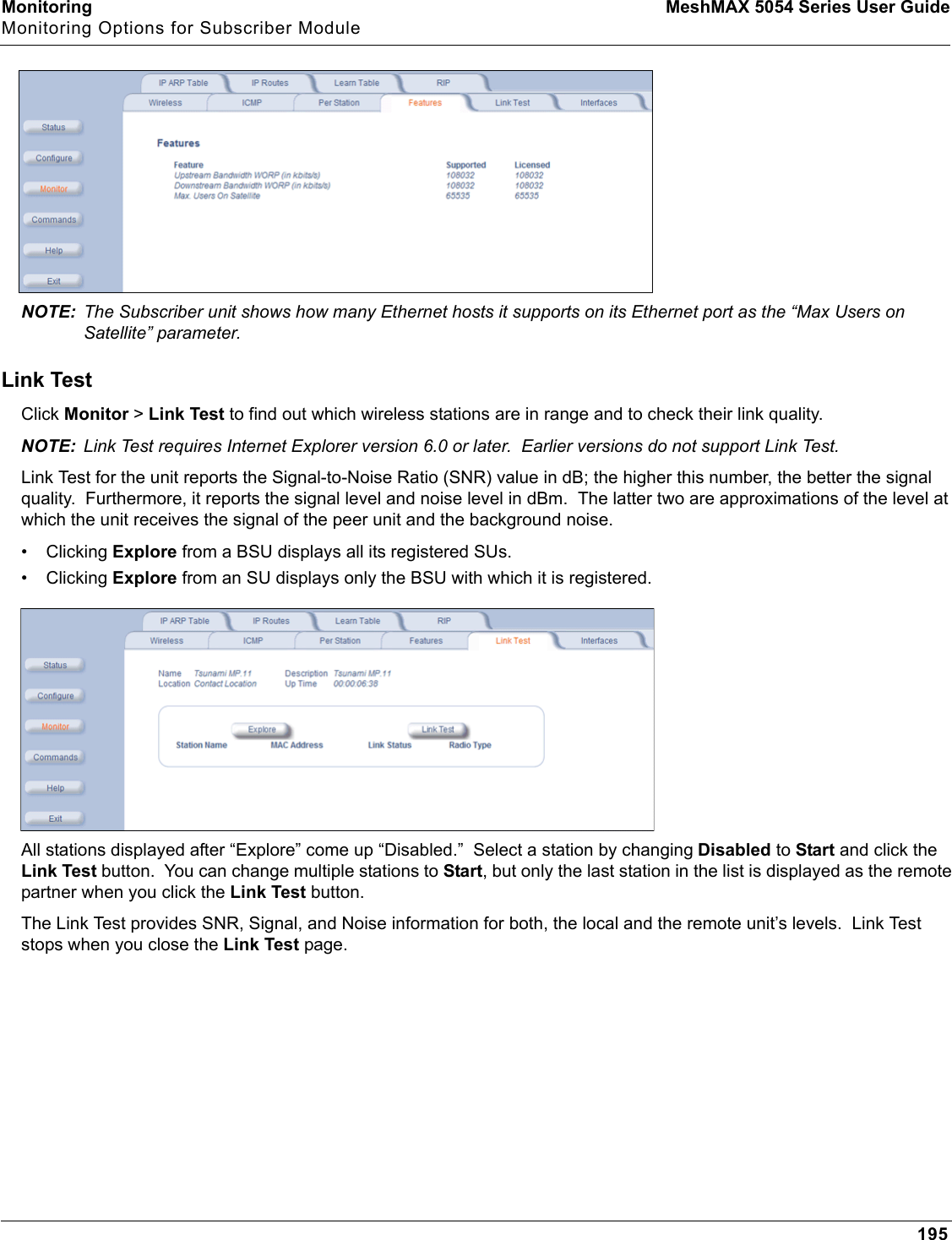
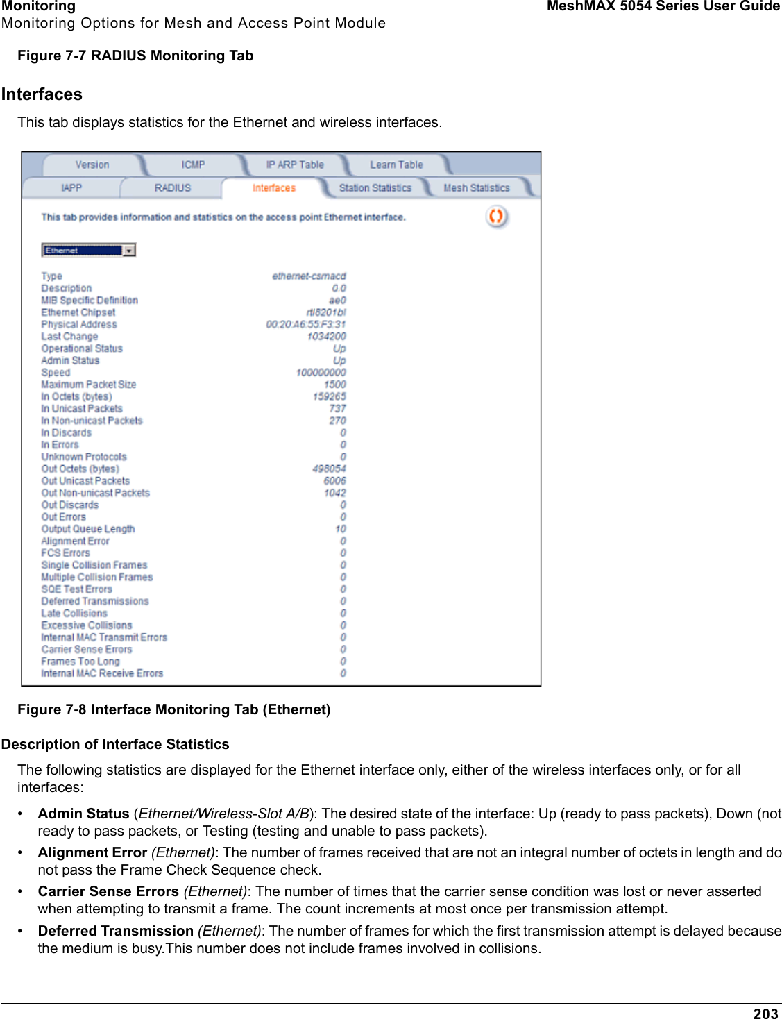
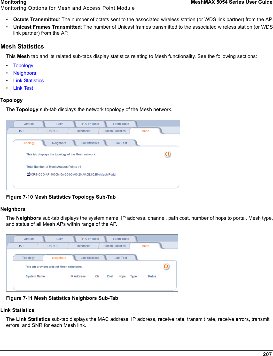
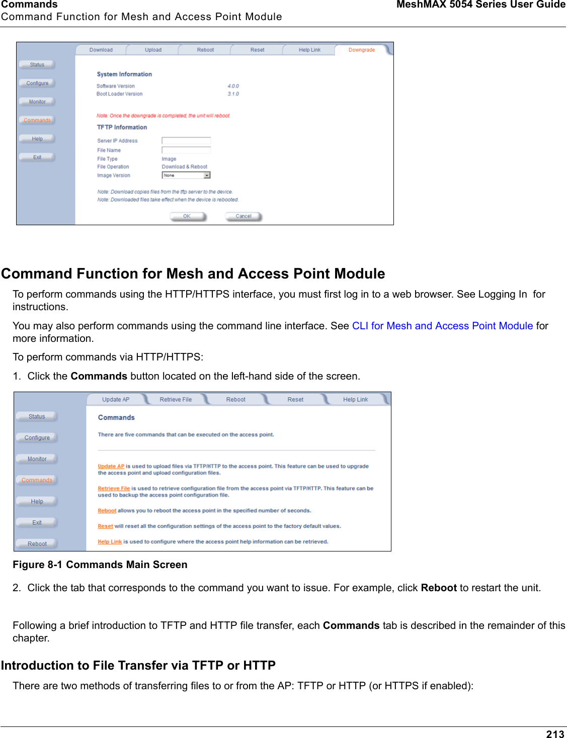
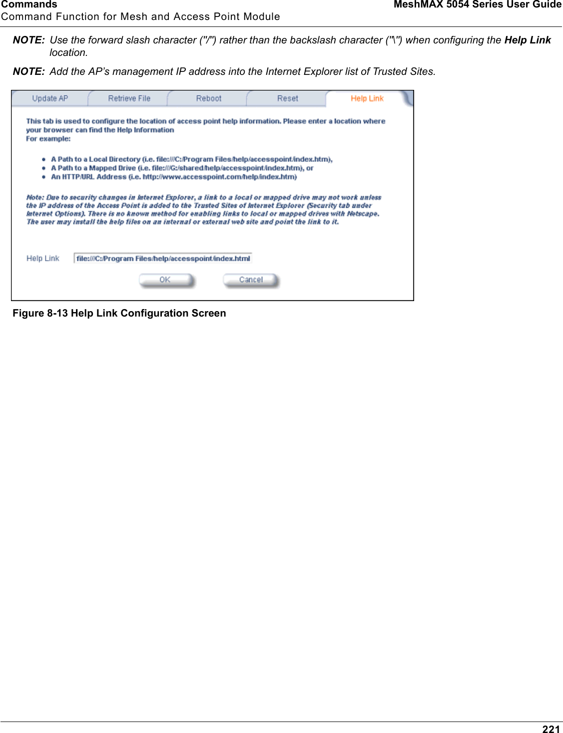
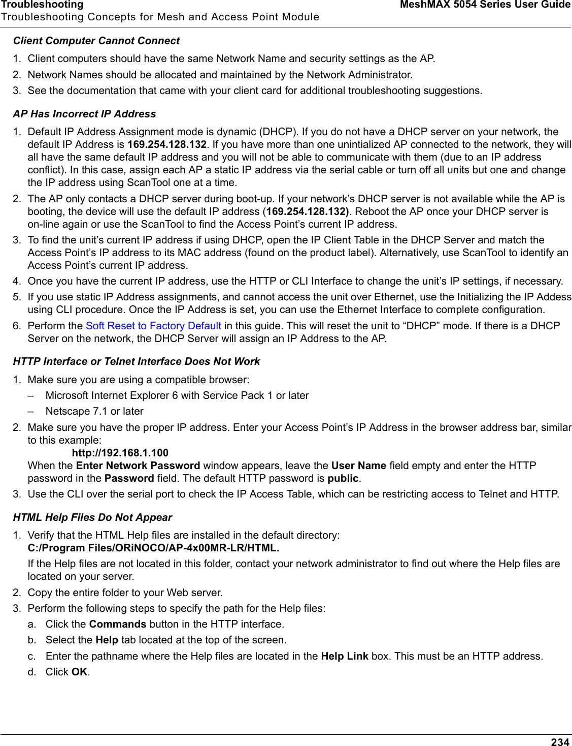
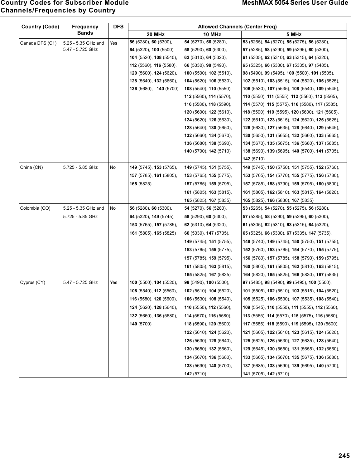
![Configuration MeshMAX 5054 Series User GuideAdvanced Configuration of Mesh and Access Point Module1772. Set the VLAN Management ID to a value of between 1 and 4094. (A value of -1 disables VLAN Tagging).3. Place a check mark in the Enable VLAN Tagging box.Provide Access to a Wireless Host in the Same WorkgroupThe VLAN feature can allow wireless clients to manage the AP. If the VLAN Management ID matches a VLAN User ID, then those wireless clients who are members of that VLAN will have AP management access.CAUTION: Once a VLAN Management ID is configured and is equivalent to one of the VLAN User IDs on the AP, all members of that User VLAN will have management access to the AP. Be careful to restrict VLAN membership to those with legitimate access to the AP.NOTE: When VLAN is enabled, ensure that all devices in the network share the same VLAN ID.1. Click Configure > SSID/VLAN/Security > Mgmt VLAN.2. Set the VLAN Management ID to use the same VLAN ID as one of the configured SSIDs. 3. Place a check mark in the Enable VLAN Tagging box.Disable VLAN Tagging1. Click Configure > SSID/VLAN/Security > Mgmt VLAN.2. Remove the check mark from the Enable VLAN Tagging box (to disable all VLAN functionality) or set the VLANManagement ID to -1 (to disable VLAN Tagging only).NOTE: If you disable VLAN Tagging, you will be unable to configure security per SSID.Security ProfileSee the following sections:•Security Features•Authentication Protocol Hierarchy•VLANs and Security Profiles•Configuring Security ProfilesSecurity FeaturesThe AP supports the following security features:•WEP Encryption: The original encryption technique specified by the IEEE 802.11 standard.•802.1x Authentication: An IEEE standard for client authentication.•Wi-Fi Protected Access (WPA/802.11i [WPA2]): A new standard that provides improved encryption security over WEP.NOTE: The AP does not support shared key 802.11 MAC level authentication. Clients with this MAC level feature must disable it.WEP EncryptionThe IEEE 802.11 standards specify an optional encryption feature, known as Wired Equivalent Privacy or WEP, that is designed to provide a wireless LAN with a security level equal to what is found on a wired Ethernet network. WEP encrypts the data portion of each packet exchanged on an 802.11 network using an Encryption Key (also known as a WEP Key).When Encryption is enabled, two 802.11 devices must have the same Encryption Keys and both devices must be configured to use Encryption in order to communicate. If one device is configured to use Encryption but a second device is not, then the two devices will not communicate, even if both devices have the same Encryption Keys.](https://usermanual.wiki/Proxim-Wireless/MESHMAXMP11R.Users-Manual-2-part-2/User-Guide-1030887-Page-29.png)
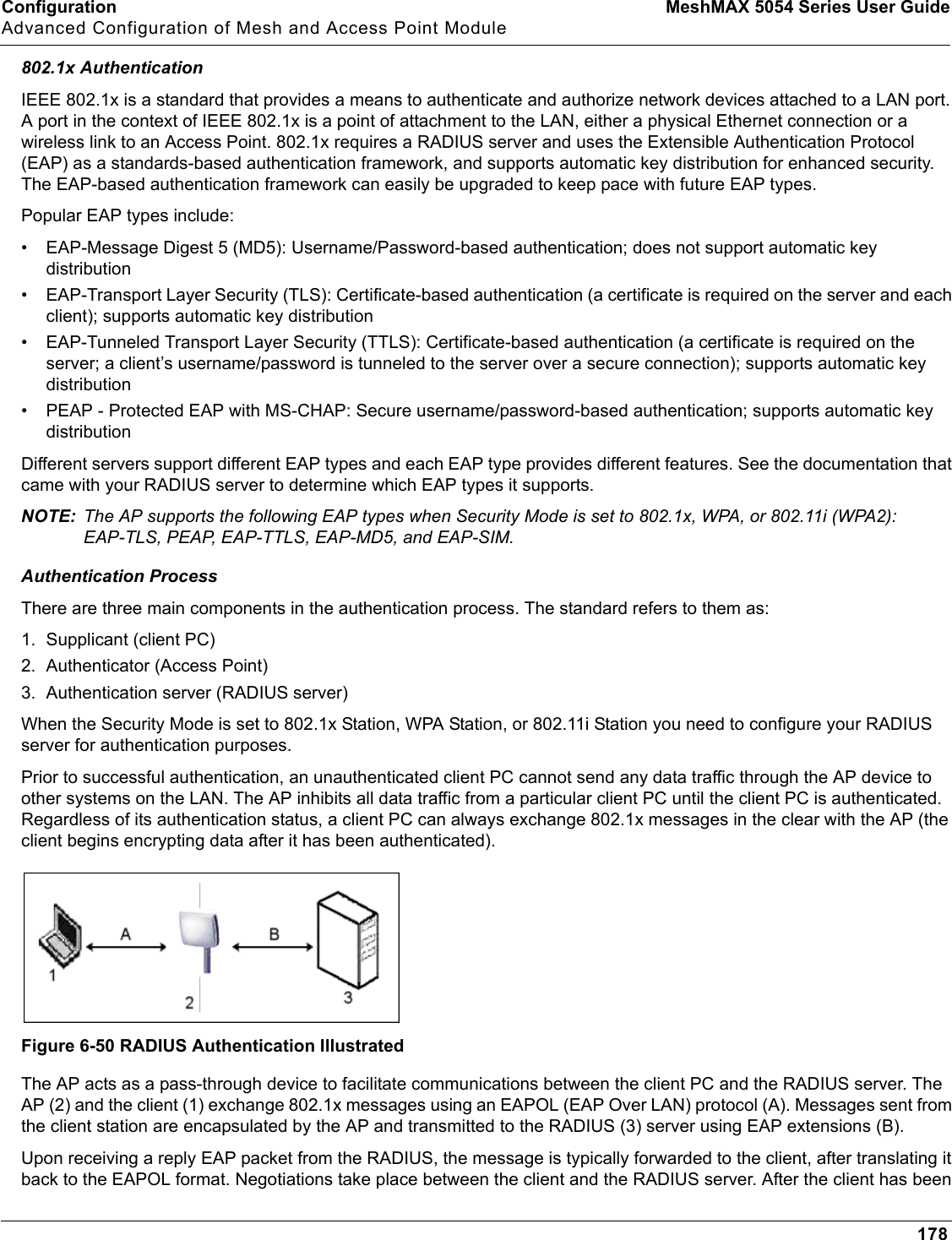
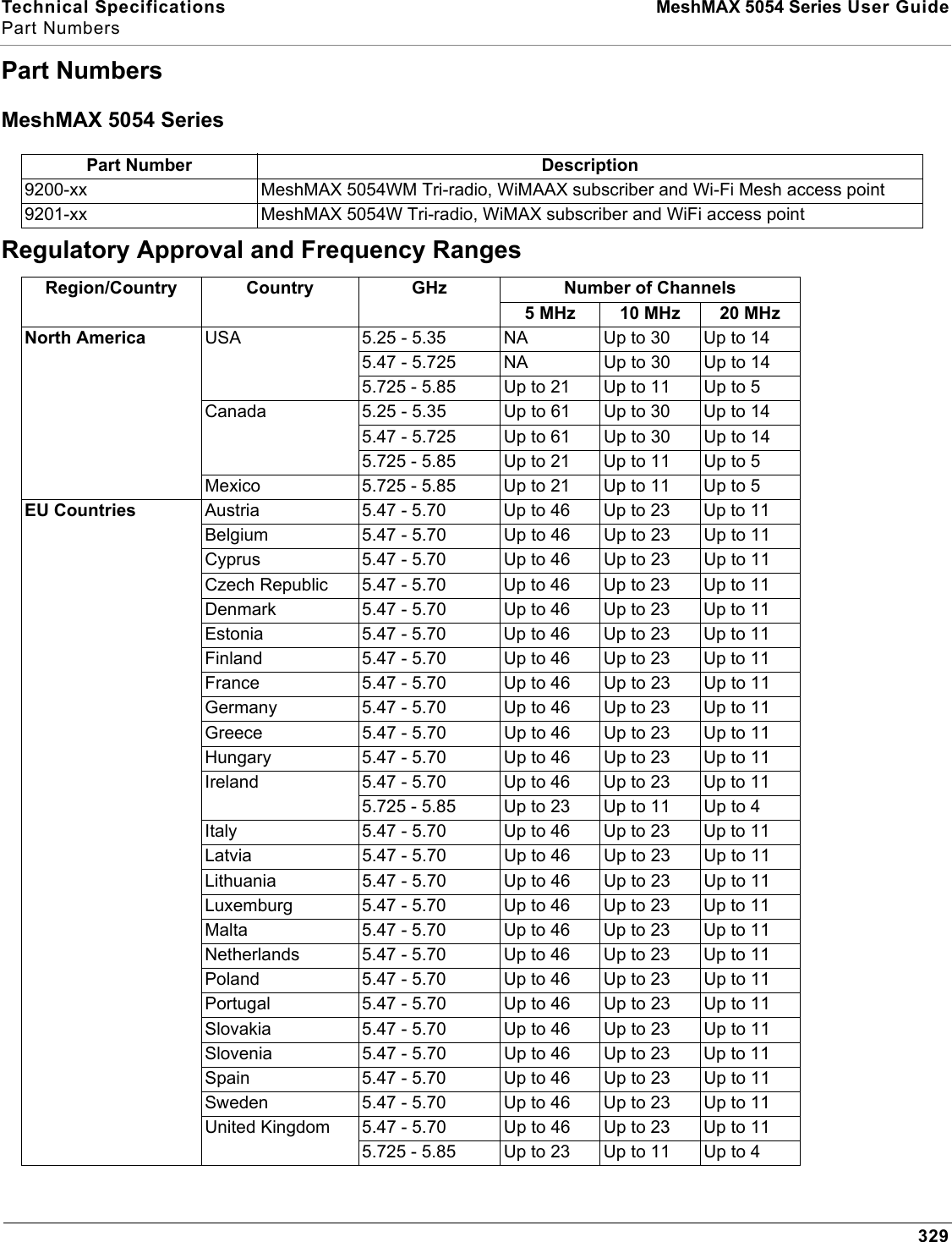
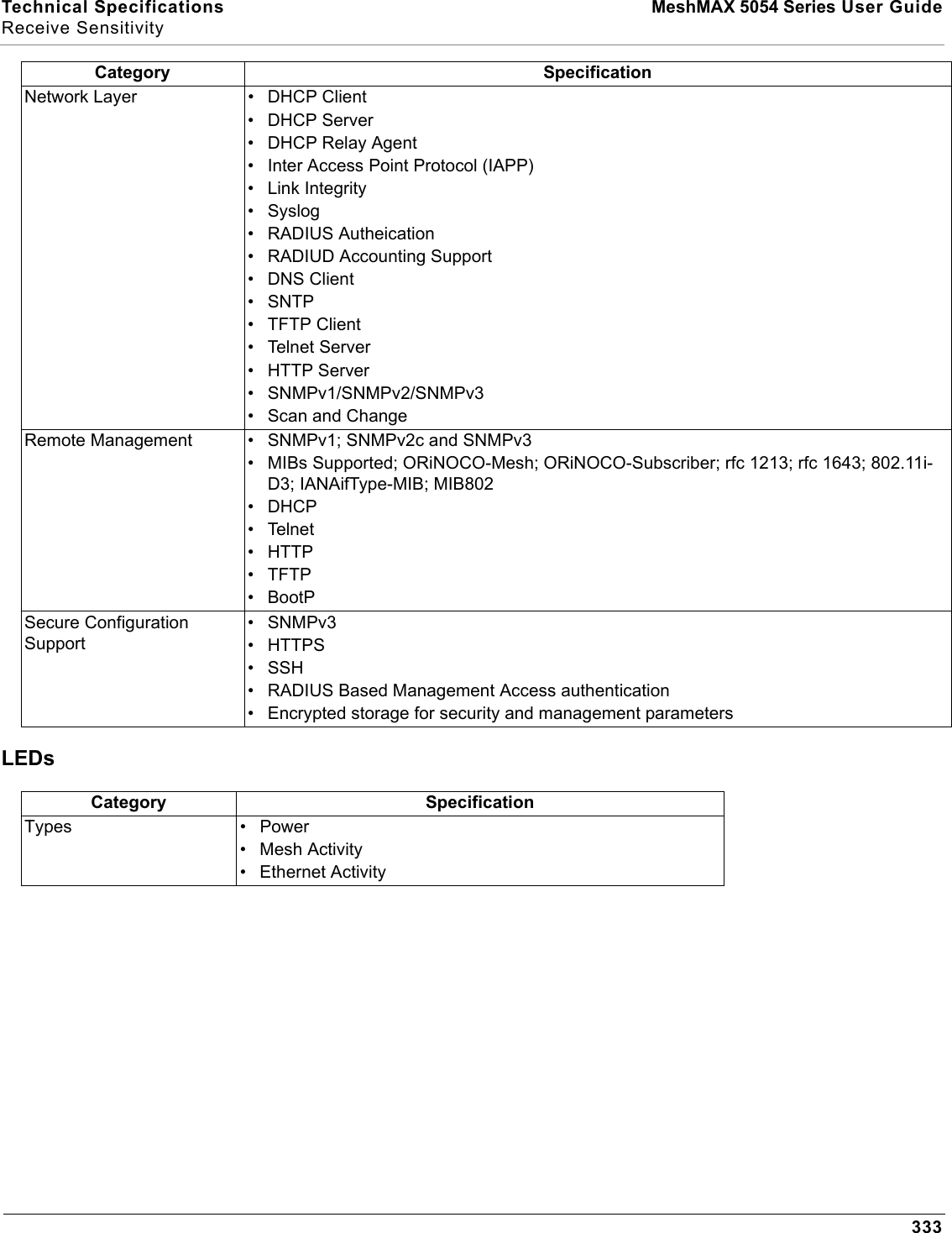
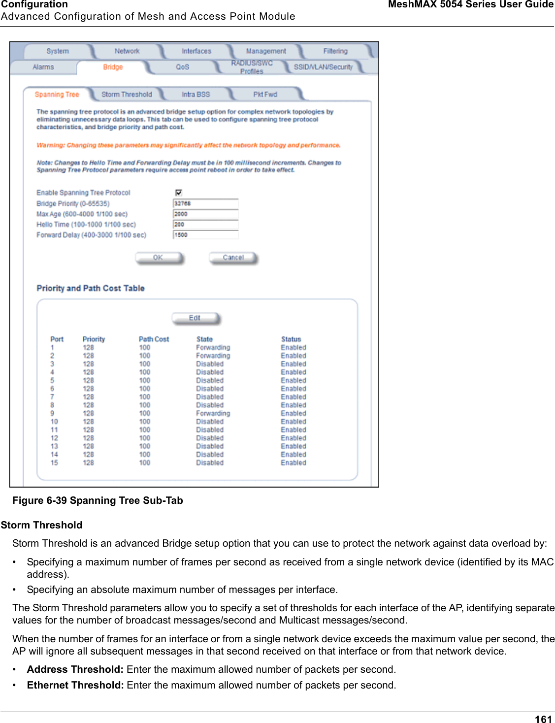
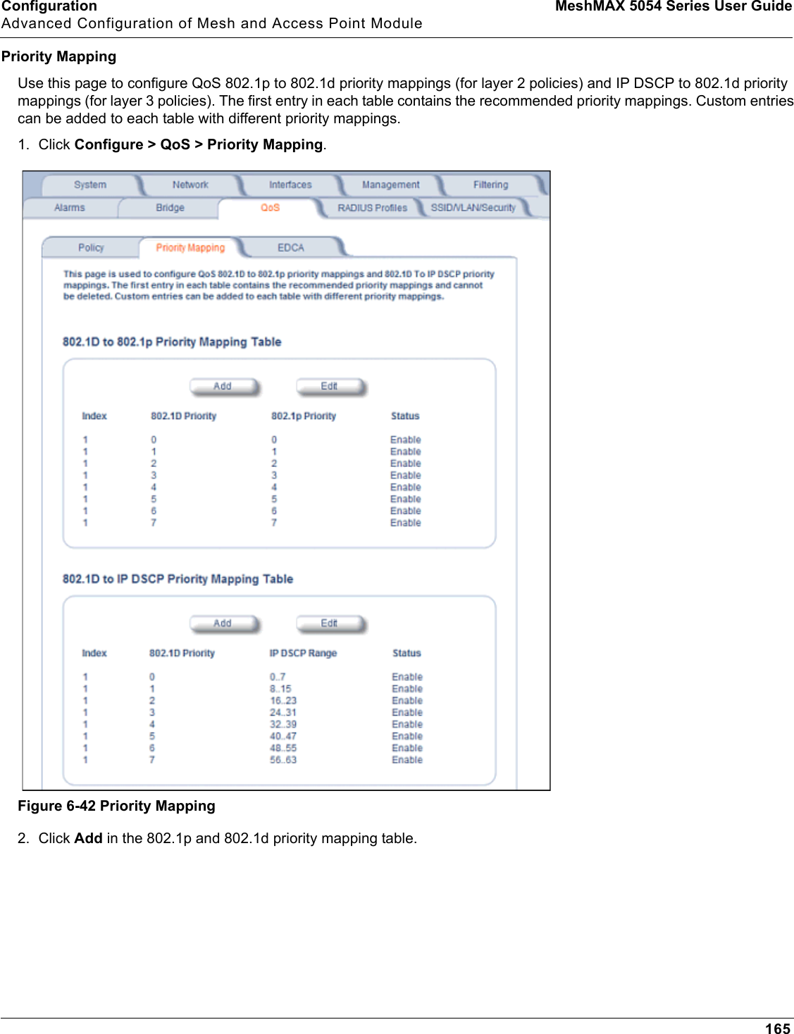
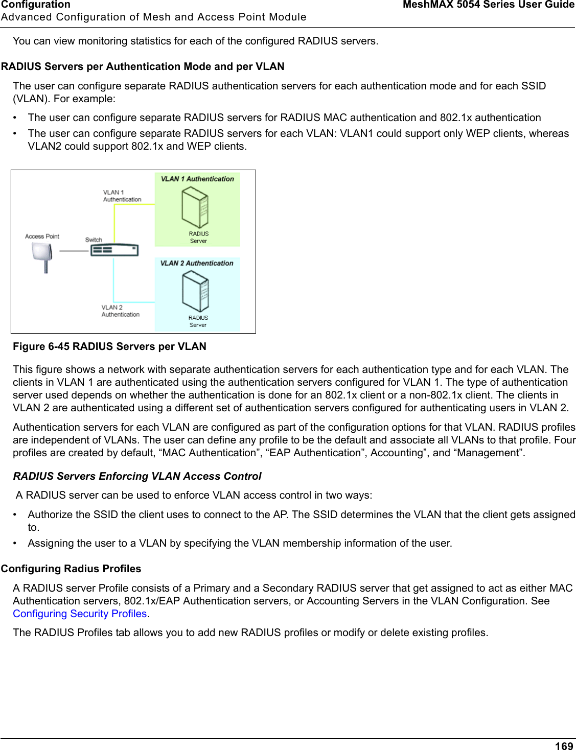
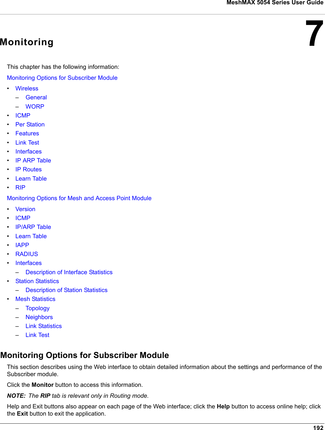
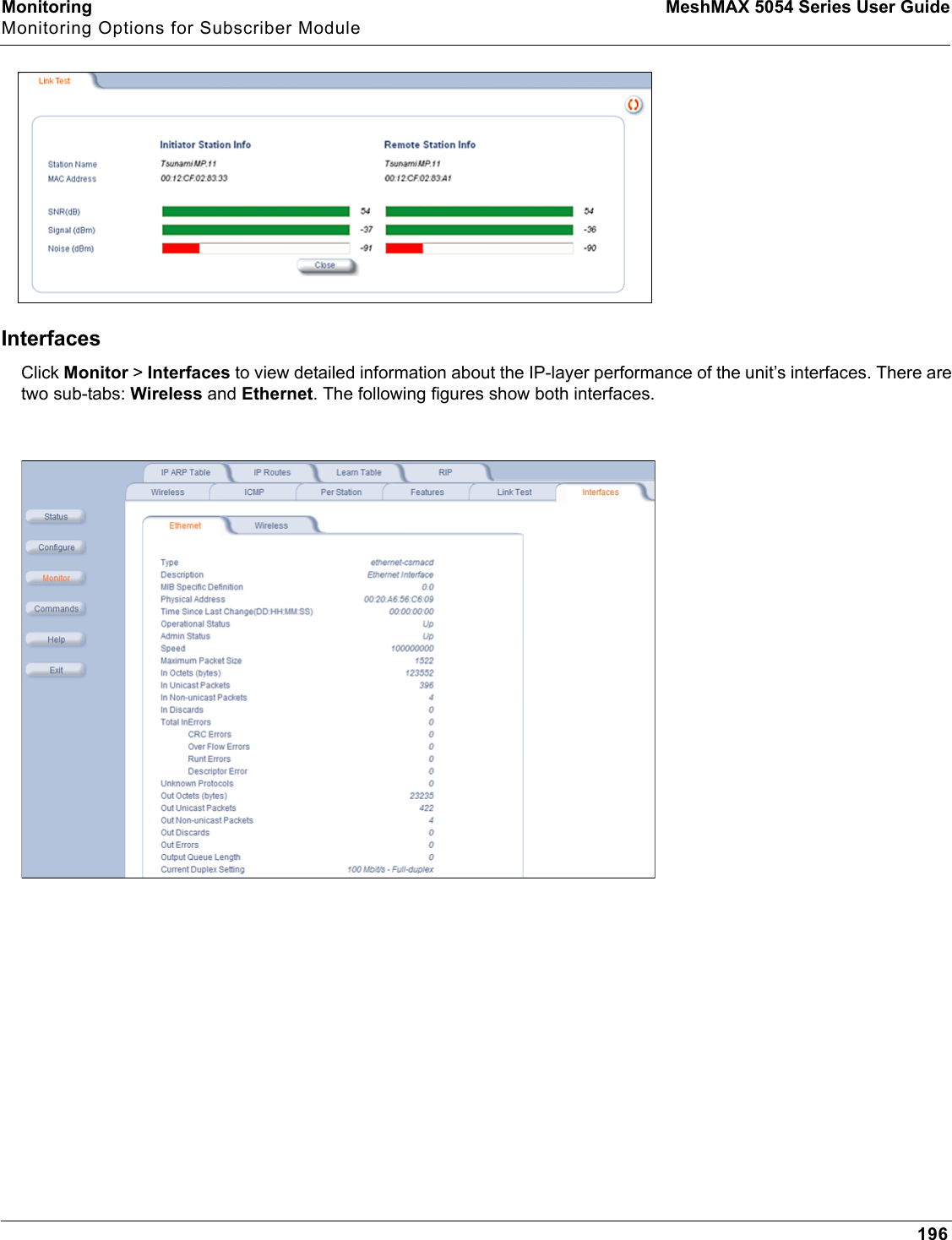
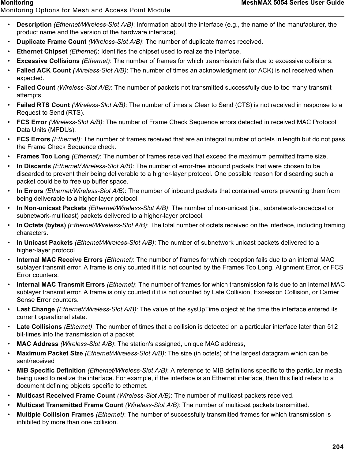
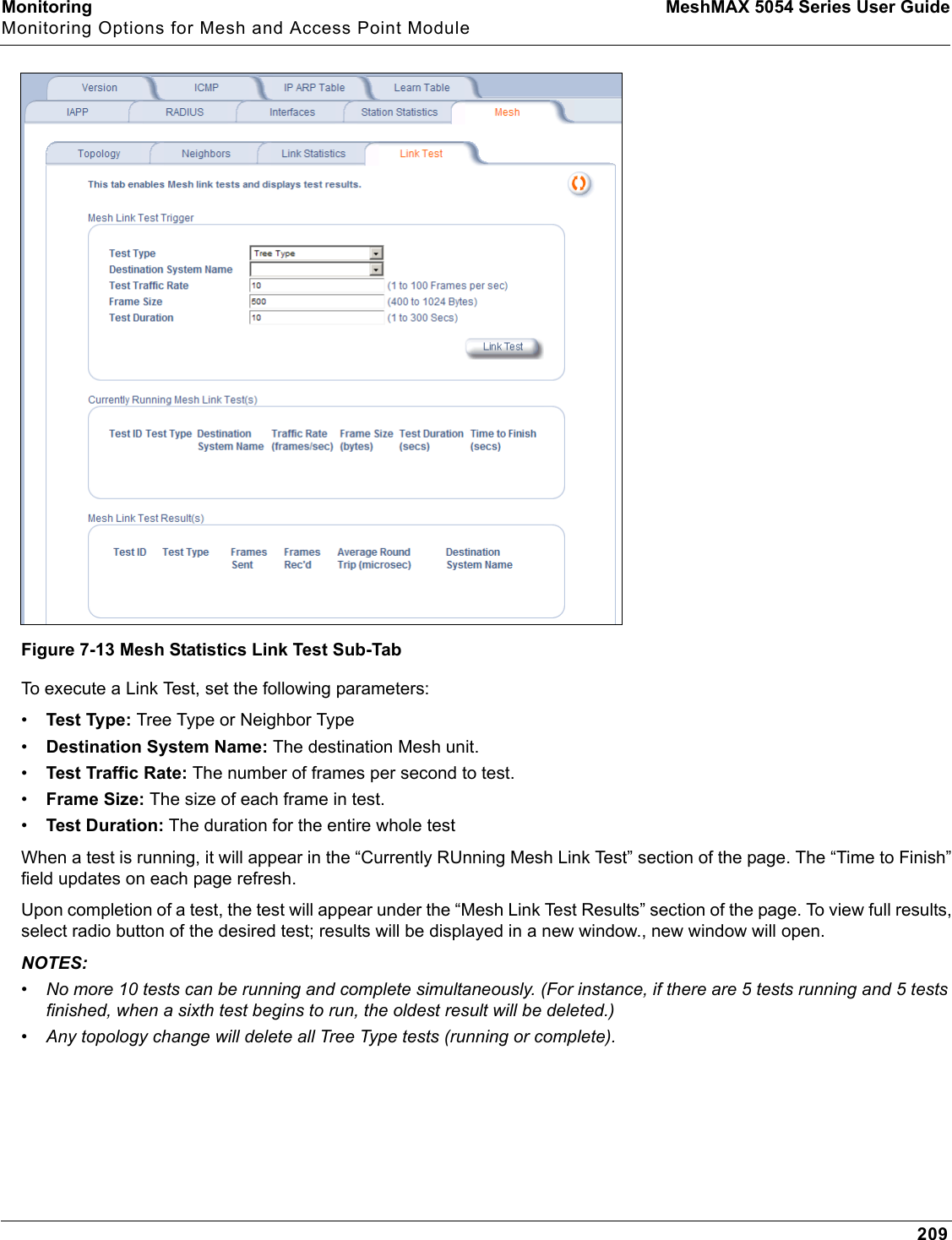
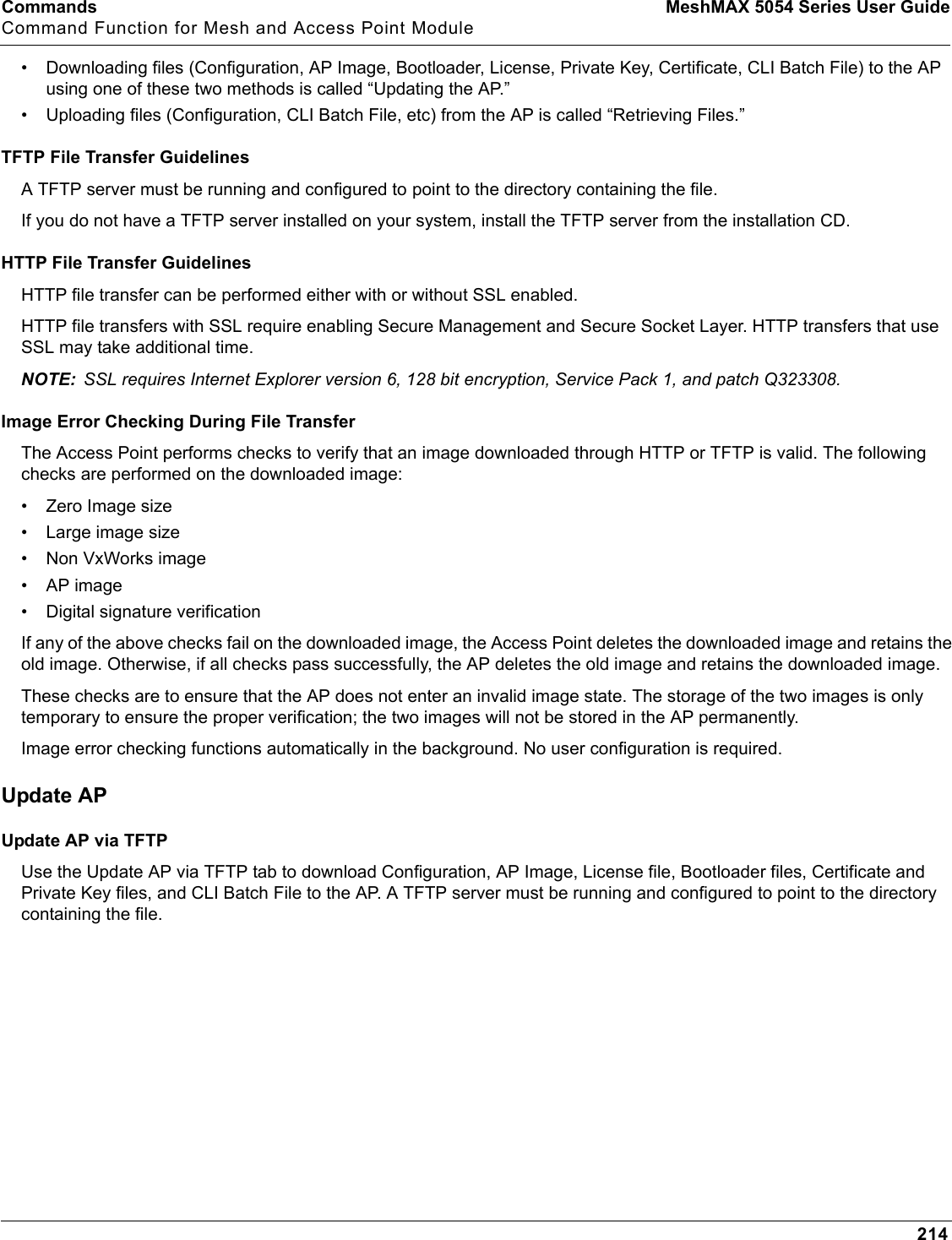
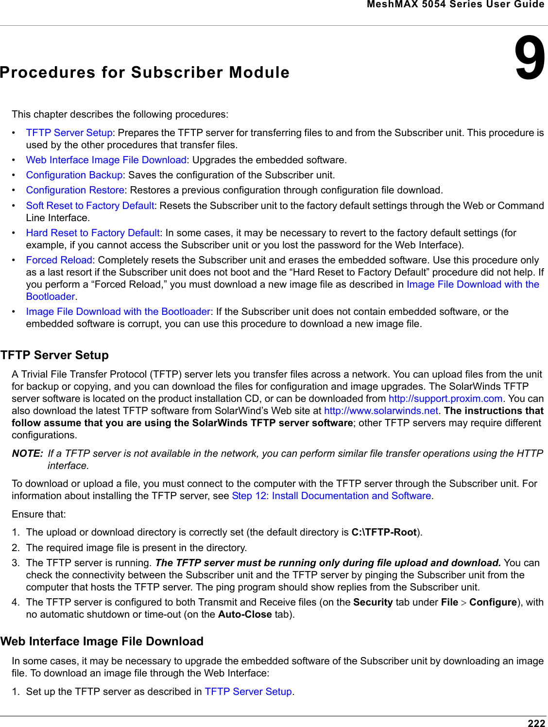
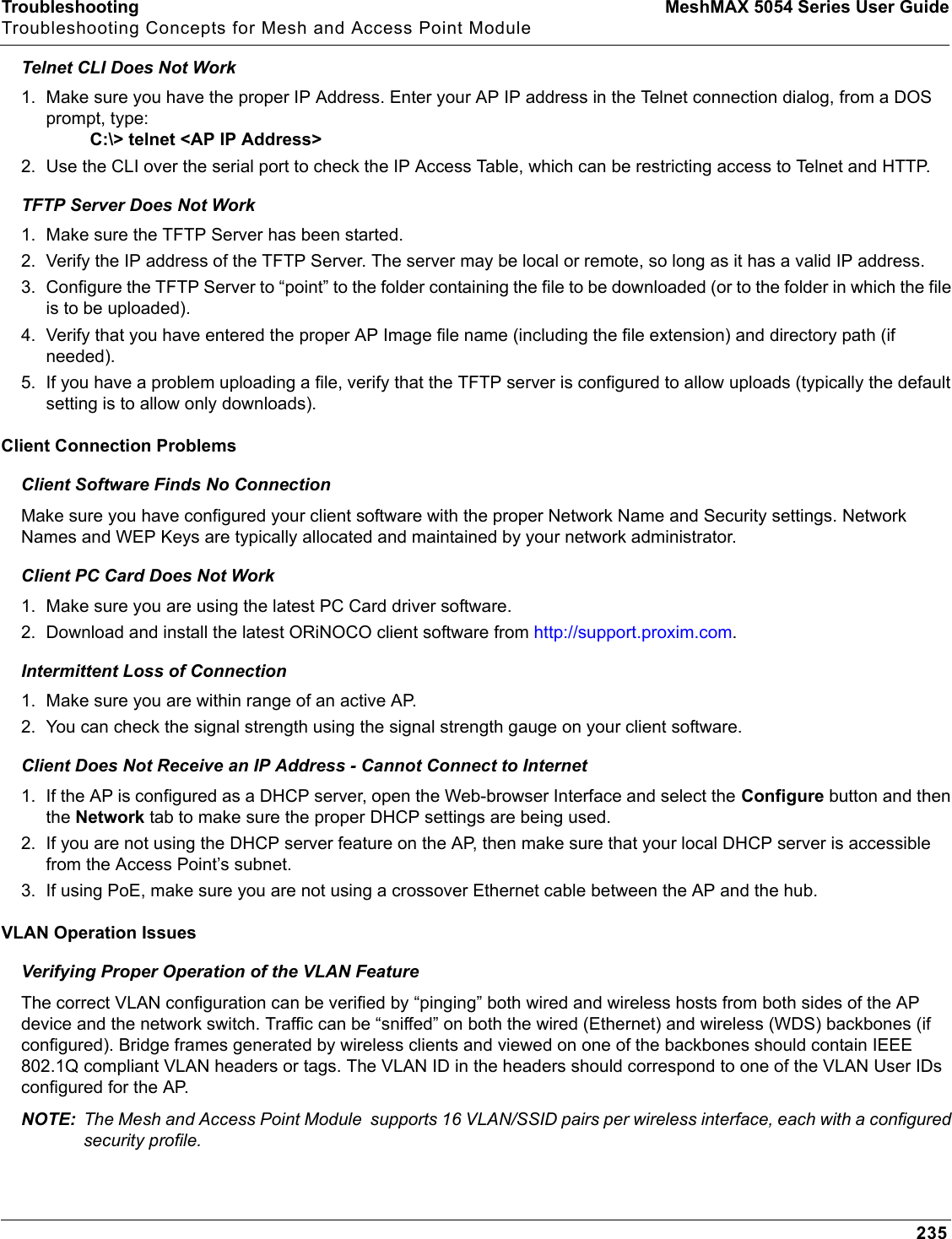
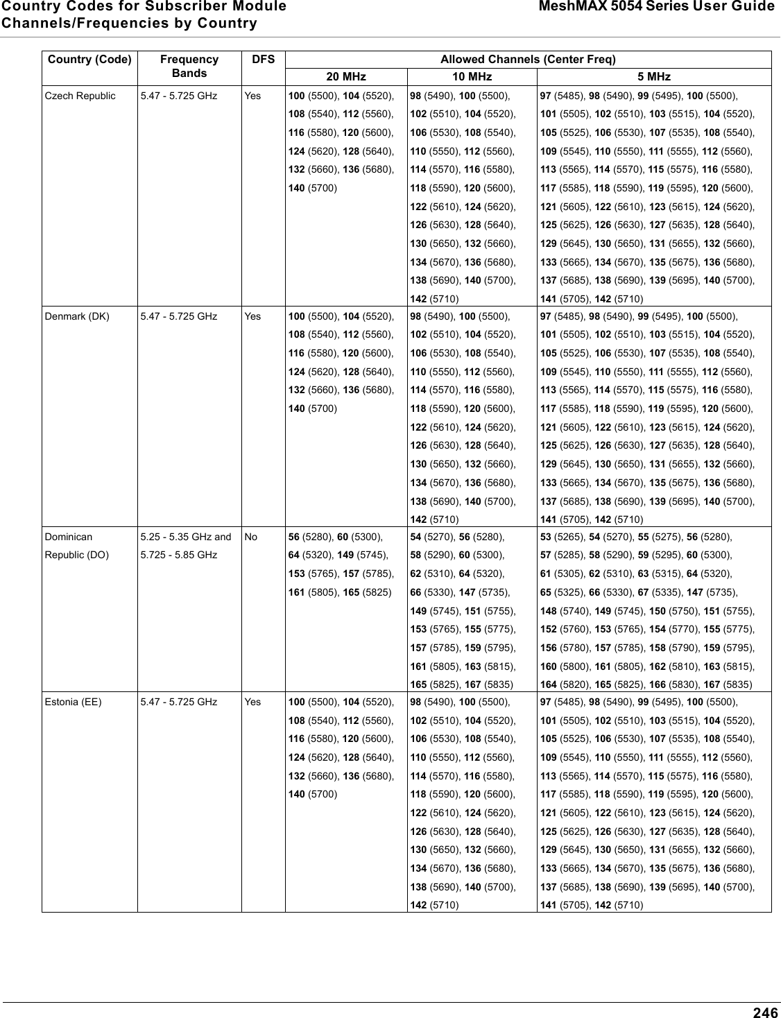
![Configuration MeshMAX 5054 Series User GuideAdvanced Configuration of Mesh and Access Point Module179successfully authenticated, the client receives an Encryption Key from the AP (if the EAP type supports automatic key distribution). The client uses this key to encrypt data after it has been authenticated. For 802.11a, 4.9 GHz, and 802.11b/g clients that communicate with an AP, each client receives its own unique encryption key; this is known as Per User Per Session Encryption Keys.Wi-Fi Protected Access (WPA/802.11i [WPA2])Wi-Fi Protected Access (WPA) is a security standard designed by the Wi-Fi Alliance in conjunction with the Institute of Electrical and Electronics Engineers (IEEE). The AP supports 802.11i (WPA2), based on the IEEE 802.11i security standard.WPA is a replacement for Wired Equivalent Privacy (WEP), the encryption technique specified by the original 802.11 standard. WEP has several vulnerabilities that have been widely publicized. WPA addresses these weaknesses and provides a stronger security system to protect wireless networks.WPA provides the following new security measures not available with WEP:• Improved packet encryption using the Temporal Key Integrity Protocol (TKIP) and the Michael Message Integrity Check (MIC).• Per-user, per-session dynamic encryption keys:– Each client uses a different key to encrypt and decrypt unicast packets exchanged with the AP– A client's key is different for every session; it changes each time the client associates with an AP– The AP uses a single global key to encrypt broadcast packets that are sent to all clients simultaneously– Encryption keys change periodically based on the Re-keying Interval parameter– WPA uses 128-bit encryption keys• Dynamic Key distribution– The AP generates and maintains the keys for its clients– The AP securely delivers the appropriate keys to its clients• Client/server mutual authentication–802.1x– Pre-shared key (for networks that do not have an 802.1x solution implemented)The AP supports the following WPA security modes:•WPA: The AP uses 802.1x to authenticate clients and TKIP for encryption. You should only use an EAP that supports mutual authentication and session key generation, such as EAP-TLS, EAP-TTLS, and PEAP. See 802.1x Authentication for details.•WPA-PSK (Pre-Shared Key): For networks that do not have 802.1x implemented, you can configure the AP to authenticate clients based on a Pre-Shared Key. This is a shared secret that is manually configured on the AP and each of its clients. The Pre-Shared Key must be 256 bits long, which is either 64 hexadecimal digits or 32 alphanumeric characters. The AP also supports a PSK Pass Phrase option to facilitate the creation of the TKIP Pre-Shared Key (so a user can enter an easy-to-remember phrase rather than a string of characters). •802.11i (also known as WPA2): The AP provides security to clients according to the 802.11i draft standard, using 802.1x authentication, a CCMP cipher based on AES, and re-keying.•802.11i-PSK (also known as WPA2 PSK): The AP uses a CCMP cipher based on AES, and encrypts frames to clients based on a Pre-Shared Key. The Pre-Shared Key must be 256 bits long, which is either 64 hexadecimal digits or 32 alphanumeric characters. The AP also supports a PSK Pass Phrase option to facilitate the creation of the Pre-Shared Key (so a user can enter an easy-to-remember phrase rather than a string of characters).NOTE: For more information on WPA, see the Wi-Fi Alliance Web site at http://www.wi-fi.org.Authentication Protocol HierarchyThere is a hierarchy of authentication protocols defined for the AP. The hierarchy is as follows, from highest to lowest:](https://usermanual.wiki/Proxim-Wireless/MESHMAXMP11R.Users-Manual-2-part-2/User-Guide-1030887-Page-31.png)

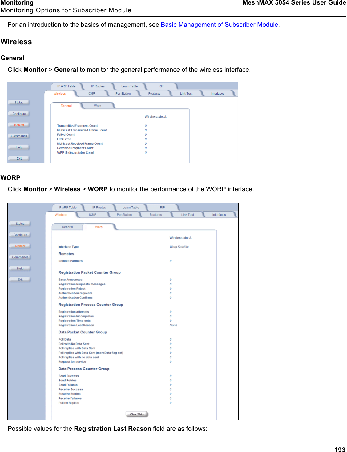
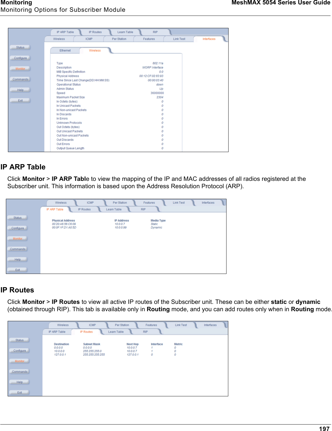
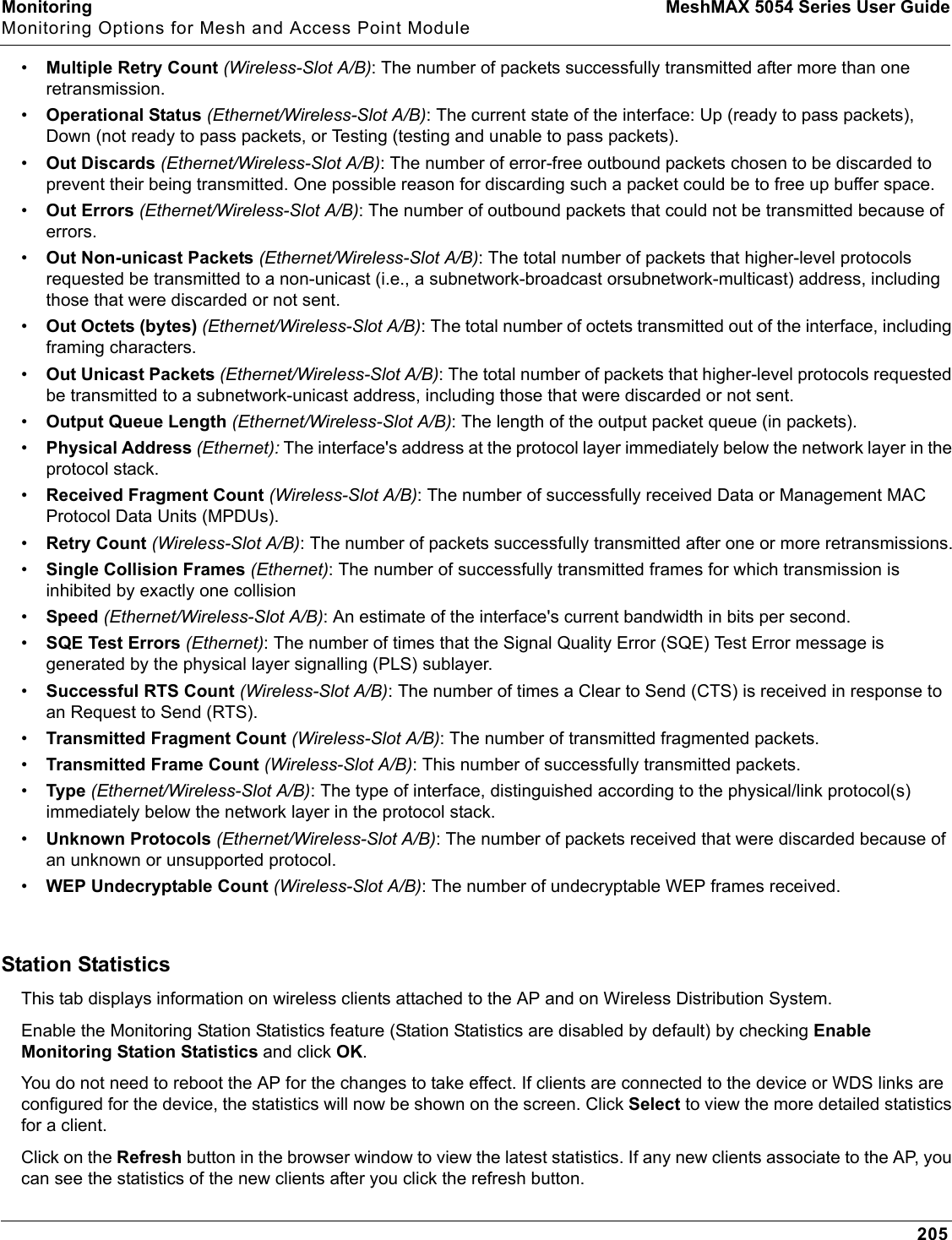

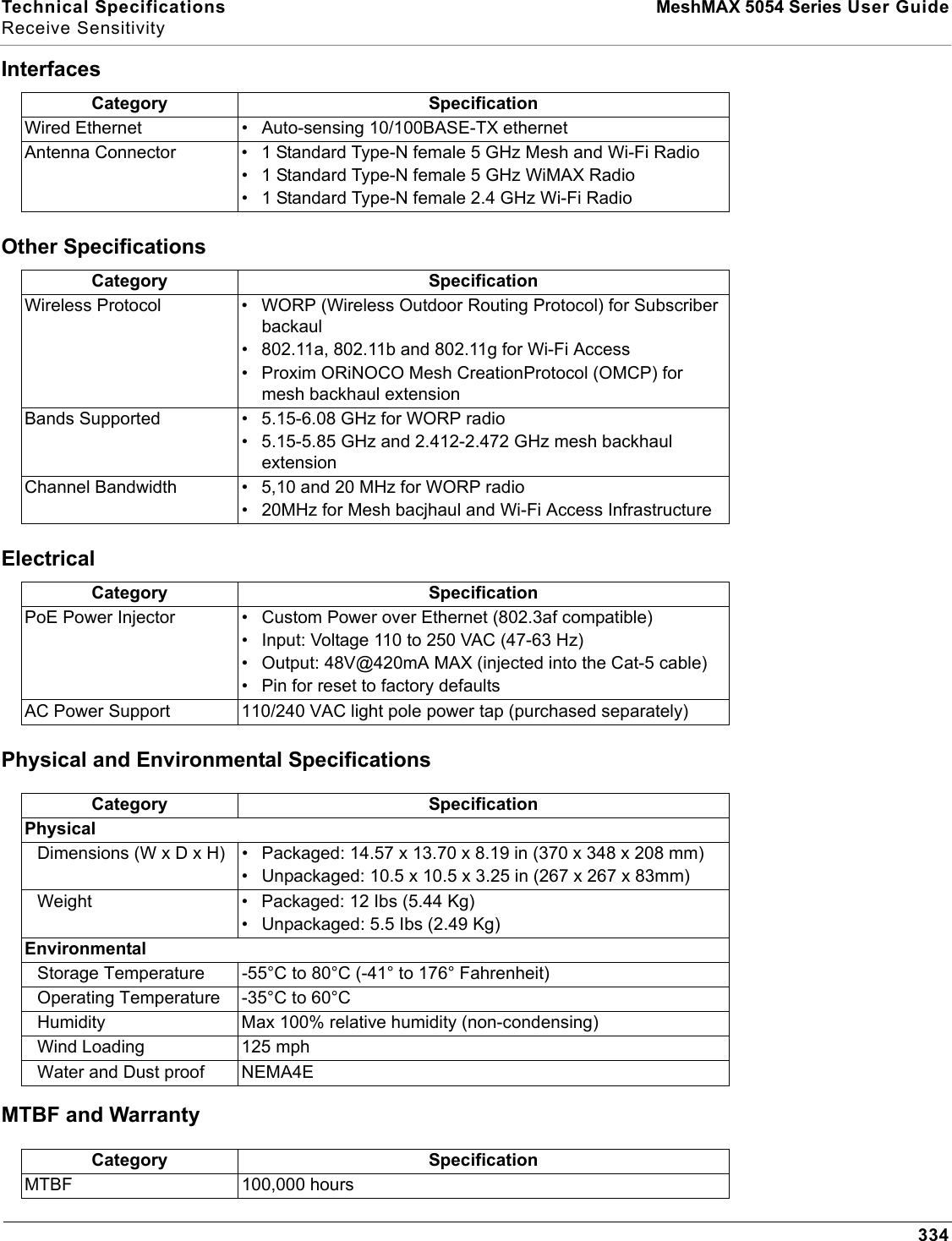
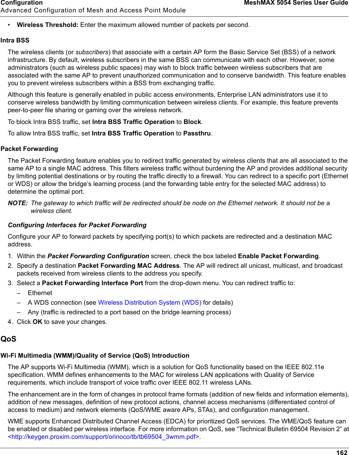
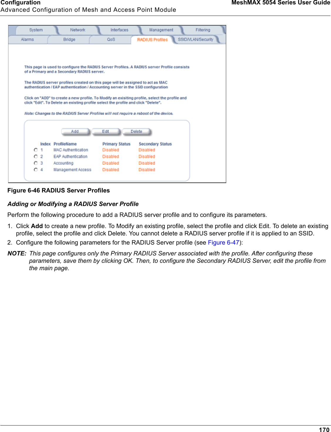
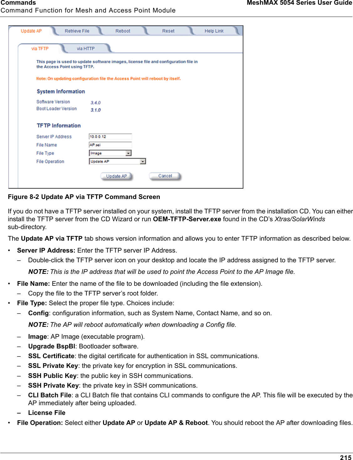
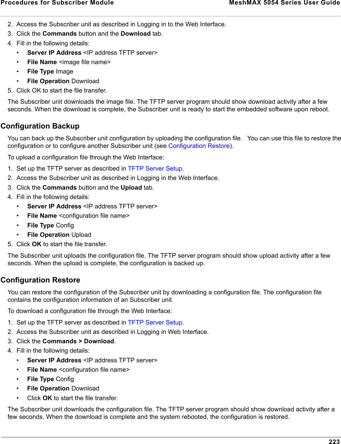
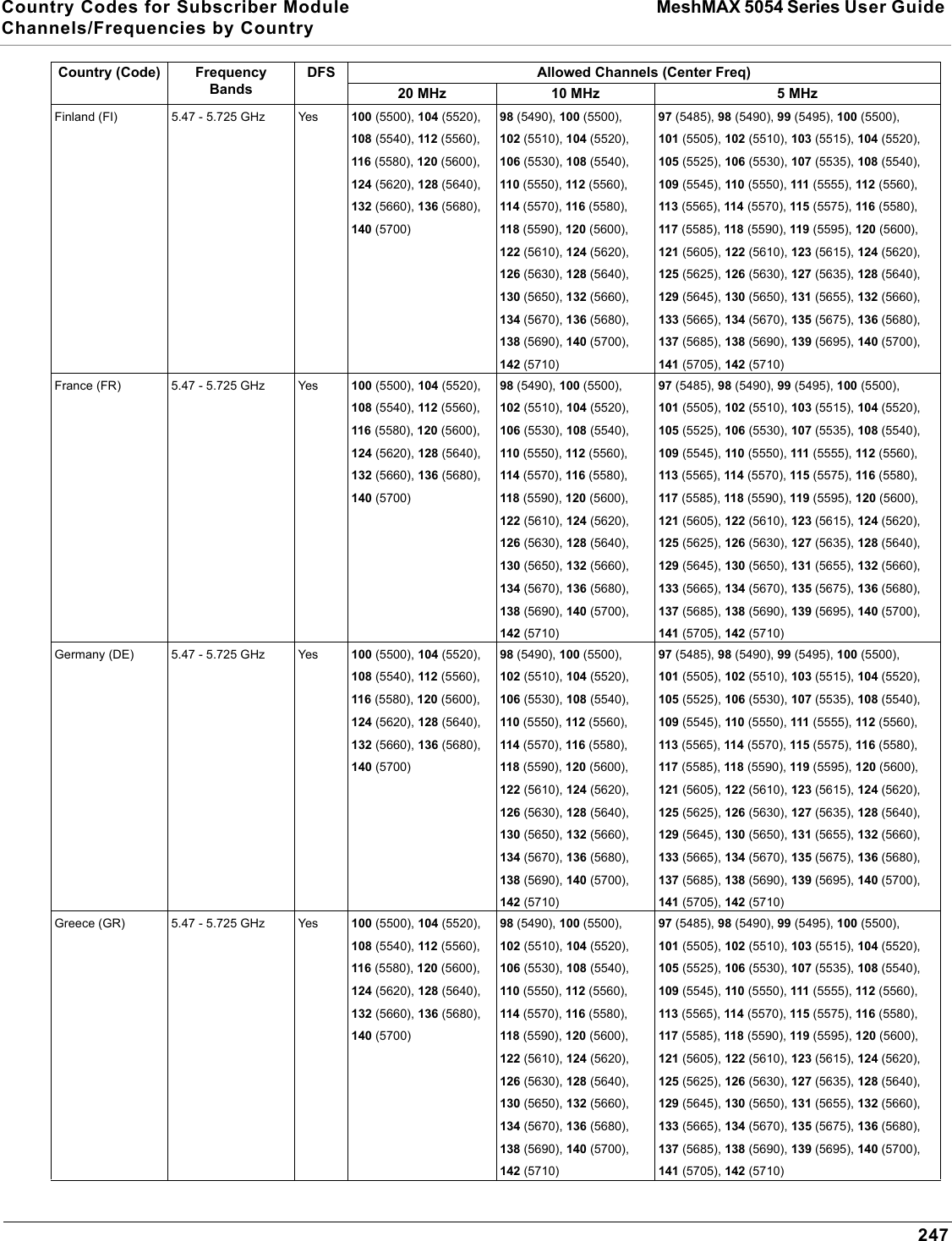
![Commands MeshMAX 5054 Series User GuideCommand Functions for Subscriber Module212CAUTION: Rebooting the unit causes all users currently connected to lose their connection to the network until the Subscriber unit has completed the reboot process and resumed operation.ResetClick Commands > Reset to restore the configuration of the Subscriber unit to the factory default values.You can also reset the Subscriber unit by pressing the RESET button located on the side of the unit. Because this resets the unit’s current IP address, a new IP address must be assigned.CAUTION: Resetting the unit to its factory default configuration permanently overwrites all changes made to the unit. The unit reboots automatically after this command has been issued.Help LinkClick Commands>Help Link to set the location of the help files of the Web Interface. Upon installation, the help files are installed in the C:\Program Files\Tsunami\[Model Name]\Help folder.If you want to place these files on a shared drive, copy the Help folder to the new location and specify the new path in the Help Link box.DowngradeClick Commands > Downgrade to downgrade to a previous release. Downgrade currently is supported only to release 2.0.1 and later. Once you enter this command, the unit is downgraded to the specified release and is automatically rebooted. The filename specified and the filename of the image selected for downgrade must be the same version. The unit will download the file, re-format the configuration to match the version, and reboot to put the image into effect.](https://usermanual.wiki/Proxim-Wireless/MESHMAXMP11R.Users-Manual-2-part-2/User-Guide-1030887-Page-64.png)
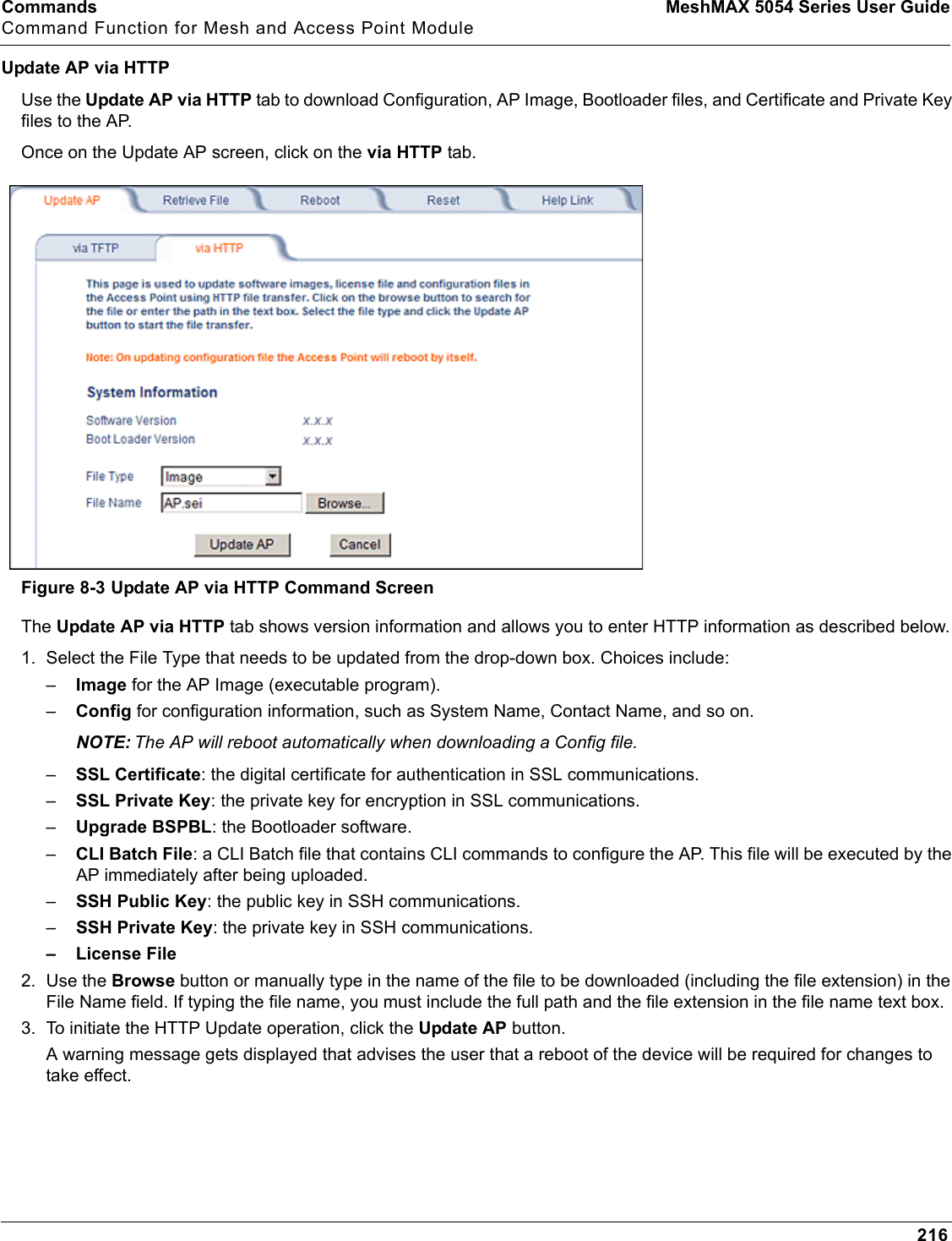

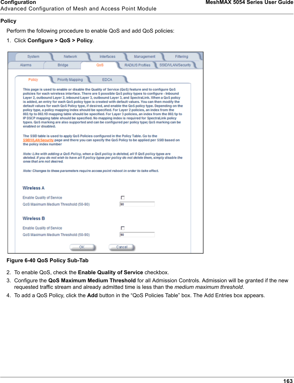
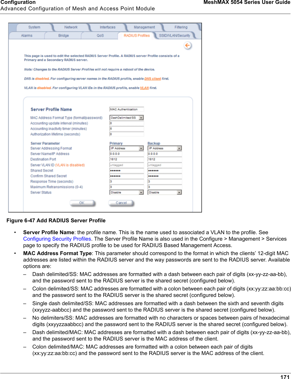
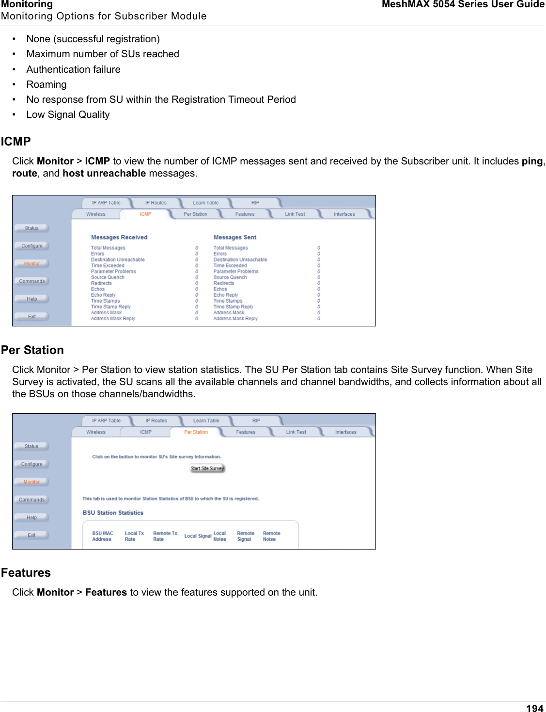
![Troubleshooting MeshMAX 5054 Series User GuideTroubleshooting Concepts for Mesh and Access Point Module239• Flow Control: None• Parity: None5. Under File > Properties > Settings > ASCII Setup, enable the Send line ends with line feeds option. HyperTerminal sends a line return at the end of each line of code.6. Press the RESET button on the AP. The terminal display shows Power On Self Tests (POST) activity. After approximately 30 seconds, a message indicates: Sending Traps to SNMP manager periodically. After this message appears, press the ENTER key repeatedly until the following prompt appears:[Device name]>7. Enter only the following statements:[Device name]> show (to view configuration parameters and values)[Device name]> set ipaddrtype static[Device name]> set ipaddr <Access Point IP Address>[Device name]> set ipsubmask <IP Mask>[Device name]> set tftpipaddr <TFTP Server IP Address>[Device name]> set tftpfilename <AP Image File Name, including file extension>[Device name]> set ipgw <Gateway IP Address>[Device name]> show (to confirm your new settings)[Device name]> rebootExample: [Device name]> show[Device name]> set ipaddrtype static[Device name]> set ipaddr 10.0.0.12[Device name]> set ipsubmask 255.255.255.0[Device name]> set tftpipaddr 10.0.0.20[Device name]> set tftpfilename MyImage.bin[Device name]> set ipgw 10.0.0.30[Device name]> show[Device name]> rebootThe AP will reboot and then download the image file. You should see downloading activity begin after a few seconds within the TFTP server’s status screen.8. When the download process is complete, configure the AP. Setting IP Address using Serial PortUse the following procedure to set an IP address over the serial port using the CLI. The network administrator typically provides the AP IP address.Hardware and Software Requirements• Standard straight-through serial data (RS-232) cable with one DB9 connector and one RJ11 connector (not included with FC units). • ASCII Terminal software, such as HyperTerminal.Attaching the Serial Port Cable1. Connect one end of the serial cable to the AP and the other end to a serial port on your computer.2. Power on the computer and AP, if necessary.](https://usermanual.wiki/Proxim-Wireless/MESHMAXMP11R.Users-Manual-2-part-2/User-Guide-1030887-Page-91.png)
![Troubleshooting MeshMAX 5054 Series User GuideTroubleshooting Concepts for Mesh and Access Point Module240Initializing the IP Address using CLIAfter installing the serial port cable, you may use the CLI to communicate with the AP. CLI supports most generic terminal emulation programs, such as HyperTerminal (which is included with the Windows operating systems). In addition, many web sites offer shareware or commercial terminal programs you can download. Once the IP address has been assigned, you can use the HTTP interface or the CLI over Telnet to complete configuration.Follow these steps to assign the AP an IP address:1. Open your terminal emulation program (like HyperTerminal) and set the following connection properties:• Com Port: <COM1, COM2, etc., depending on your computer>• Baud rate: 9600•Data Bits: 8• Stop bits: 1• Flow Control: None• Parity: None2. Under File > Properties > Settings > ASCII Setup, enable the Send line ends with line feeds option. HyperTerminal sends a line return at the end of each line of code.3. Press the RESET button on the AP.The terminal display shows Power On Self Tests (POST) activity, and then displays a CLI prompt, similar to the example below. This process may take up to 90 seconds.[Device name]> Please enter password:4. Enter the CLI password (default is public).The terminal displays a welcome message and then the CLI Prompt:[Device name]>5. Enter show ip. Network parameters appear:6. Change the IP address and other network values using set and reboot CLI commands, similar to the example below (use your own IP address and subnet mask). Note that IP Address Type is set to Dynamic by default. If you have a DHCP server on your network, you should not need to manually configure the Access Point’s IP address; the Access Point will obtain an IP address from the network’s DHCP server during boot-up.After each entry the CLI reminds you to reboot; however wait to reboot until all commands have been entered. [Device name]> set ipaddrtype static[Device name]> set ipaddr <IP Address>[Device name]> set ipsubmask <IP Subnet Mask>[Device name]> set ipgw <Default Gateway IP Address>[Device name]> show ip (to confirm your new settings)[Device name]> reboot 07. After the AP reboots, verify the new IP address by reconnecting to the CLI and enter a show ip command. Alternatively, you can ping the AP from a network computer to confirm that the new IP address has taken effect.8. When the proper IP address is set, use the HTTP interface or CLI over Telnet to configure the rest of the unit’s operating parameters.Related ApplicationsRADIUS Authentication ServerIf you enabled RADIUS Authentication on the AP, make sure that your network’s RADIUS servers are operational. Otherwise, clients will not be able to log in. There are several reasons the authentication server services might be unavailable, here are two typical things to check:](https://usermanual.wiki/Proxim-Wireless/MESHMAXMP11R.Users-Manual-2-part-2/User-Guide-1030887-Page-92.png)


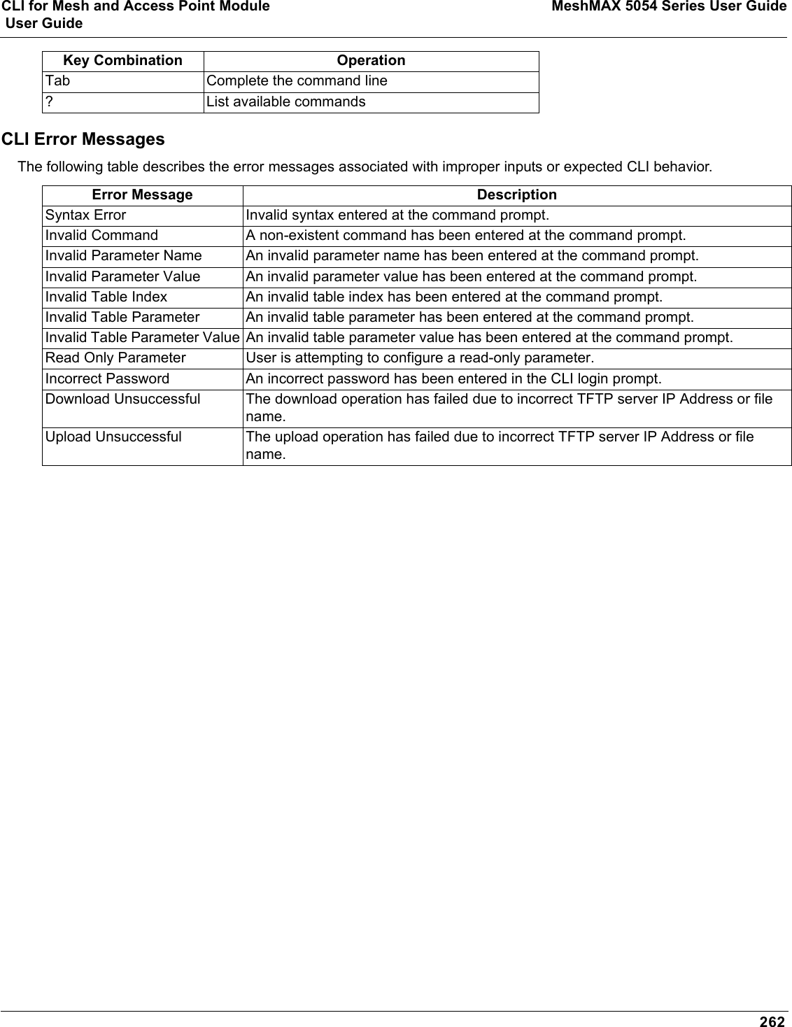
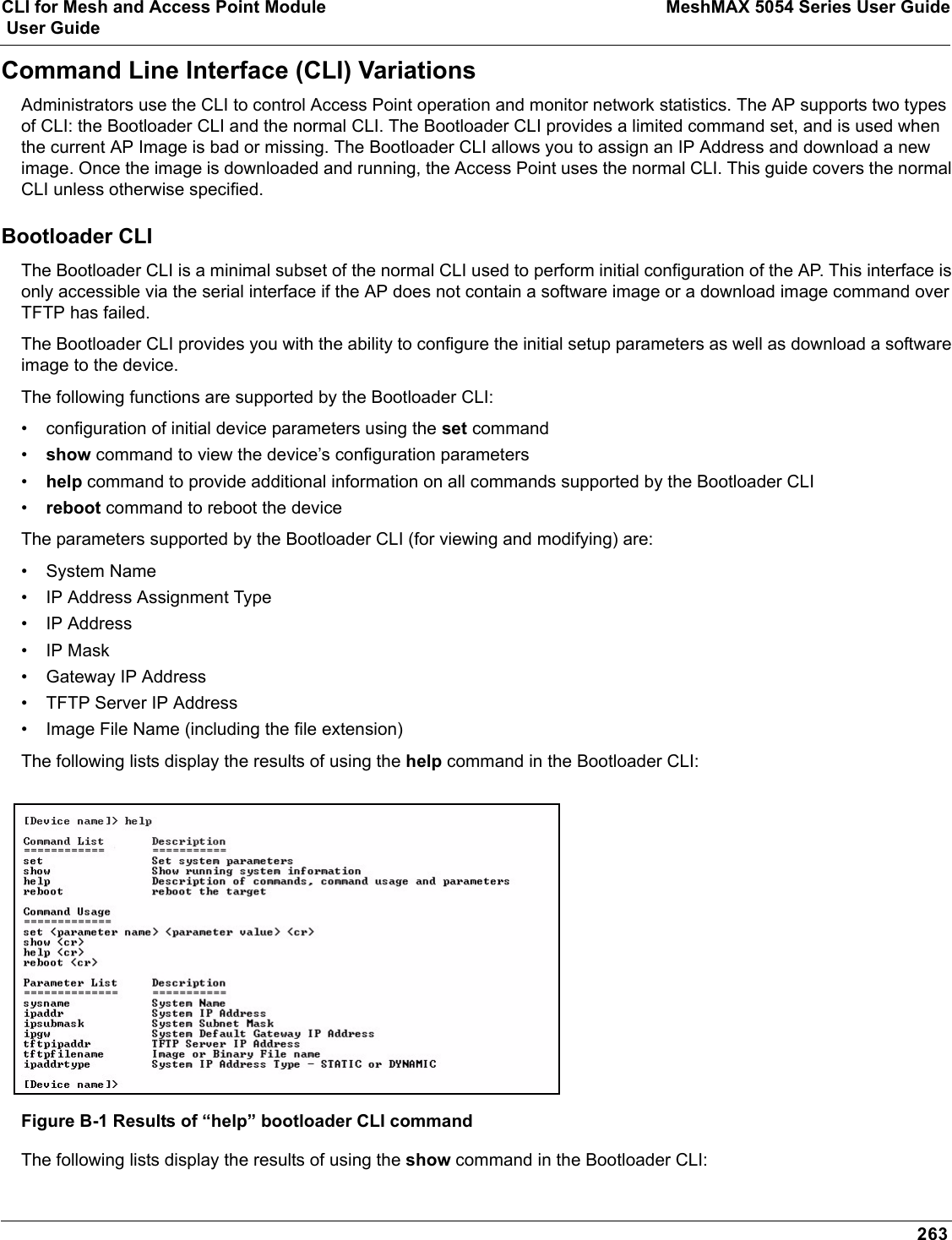
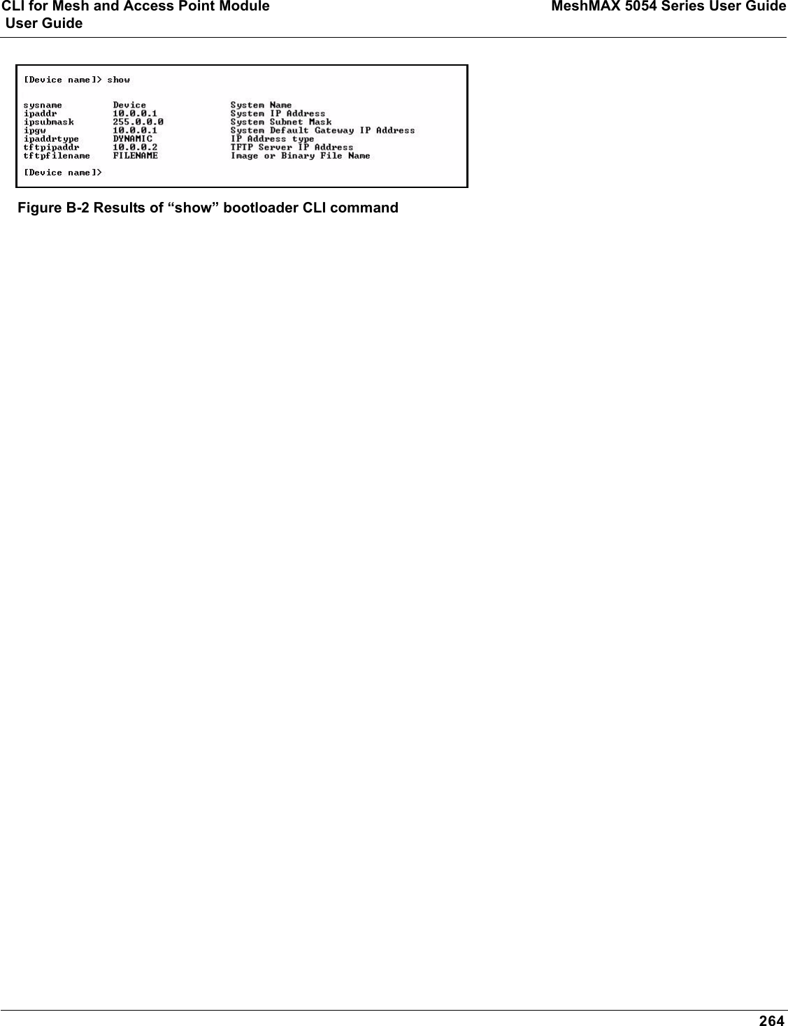
![CLI for Mesh and Access Point Module MeshMAX 5054 Series User Guide User Guide261General NotesPrerequisite Skills and KnowledgeTo use this document effectively, you should have a working knowledge of Local Area Networking (LAN) concepts, network access infrastructures, and client-server relationships. In addition, you should be familiar with software setup procedures for typical network operating systems and servers.Notation Conventions• Computer prompts are shown as constant width type. For example: [Device-Name]>• Information that you input as shown is displayed in bold constant width type. For example: [Device name]> set ipaddr 10.0.0.12• The names of keyboard keys, software buttons, and field names are displayed in bold type. For example: Click the Configure button.• Screen names are displayed in bold italics. For example, the System Status screen.Important Terminology• Configuration Files - Database files containing the current Access Point configuration. Configuration items include the IP Address and other network-specific values. Config files may be downloaded to the Access Point or uploaded for backup or troubleshooting.• Download vs. Upload - Downloads transfer files to the Access Point. Uploads transfer files from the Access Point. The TFTP server performs file transfers in both directions.• Group - A logical collection of network parameter information. For example, the System Group is composed of several related parameters. Groups can also contain Tables. All items for a given Group can be displayed with a show <Group> CLI Command.• Image File - The Access Point software executed from RAM. To update an Access Point you typically download a new Image File. This file is often referred to as the “AP Image”.• Parameter - A fundamental network value that can be displayed and may be changeable. For example, the Access Point must have a unique IP Address and the Wireless interface must be assigned an SSID. Change parameters with the CLI set Command, and view them with the CLI show Command.• Table - Tables hold parameters for several related items. For example, you can add several potential managers to the SNMP Table. All items for a given Table can be displayed with a show <Table> CLI Command.• TFTP - Refers to the TFTP Server, used for file transfers. Navigation and Special KeysThis CLI supports the following navigation and special key functions to move the cursor along the prompt line.Key Combination OperationDelete or Backspace Delete previous characterCtrl-A Move cursor to beginning of lineCtrl-E Move cursor to end of lineCtrl-F Move cursor forward one characterCtrl-B Move cursor back one characterCtrl-D Delete the character the cursor is onCtrl-U Delete all text to left of cursorCtrl-P Go to the previous line in the history bufferCtrl-N Go to the next line in the history bufferCtrl-W Delete the previous word](https://usermanual.wiki/Proxim-Wireless/MESHMAXMP11R.Users-Manual-2-part-2/User-Guide-1030887-Page-113.png)
![CLI for Mesh and Access Point Module MeshMAX 5054 Series User Guide User Guide265CLI Command TypesThis guide divides CLI Commands into two categories: Operational and Parameter Controls.Operational CLI CommandsThese commands affect Access Point behavior, such as downloading, rebooting, and so on. After entering commands (and parameters, if any) press the Enter key to execute the Command Line.Operational commands include:•?: Typing a question mark lists CLI Commands or parameters, depending on usage (you do not need to type Enter after typing this command)•done, exit, quit: Terminates the CLI session•download: Uses a TFTP server to download “image” files, “config” files, “bootloader upgrade” files, a “license” file, “SSL certificates”, “SSL private keys”, “SSH public keys”, “SSH private keys”, or “CLI Batch Files” to the Access Point•help: Displays general CLI help information or command help information, such as command usage and syntax•history: Remembers commands to help avoid re-entering complex statements•passwd: Sets the Access Point’s CLI password•reboot: Reboots the Access Point in the specified time•search: Lists the parameters in a specified Table•upload: Uses TFTP server to upload “config” files from Access Point to TFTP default directory or specified path? (List Commands) This command can be used in a number of ways to display available commands and parameters.The following table lists each operation and provides a basic example. Following the table are detailed examples and display results for each operation. Example 1. Display Command listTo display the Command List, enter ?.[Device-Name]>?Figure B-3 Result of “?” CLI commandOperation Basic ExampleDisplay the Command List (Example 1) [Device-Name]>?Display commands that start with specified letters (Example 2)[Device-Name]>s?Display parameters for set and show Commands (Examples 3a and 3b)[Device-Name]>set ?[Device-Name]>show ipa?Prompt to enter successive parameters for Commands (Example 4)[Device-Name]>download ?](https://usermanual.wiki/Proxim-Wireless/MESHMAXMP11R.Users-Manual-2-part-2/User-Guide-1030887-Page-117.png)
![CLI for Mesh and Access Point Module MeshMAX 5054 Series User Guide User Guide266Example 2. Display specific CommandsTo show all commands that start with specified letters, enter one or more letters, then ? with no space between letters and ?.[Device-Name]>s?Figure B-4 Result of “s?” CLI commandExample 3. Display parameters for set and showExample 3a allows you to see every possible parameter for the set (or show) commands. Notice from example 3a that the list is very long. Example 3b shows how to display a subset of the parameters based on initial parameter letters.Example 3a. Display every parameter that can be changed[Device-Name]>set ?Figure B-5 Result of “set ?” CLI commandExample 3b. Display parameters based on letter sequenceThis example shows entries for parameters that start with the letter “i”. The more letters you enter, the fewer the results returned. Notice that there is no space between the letters and the question mark.[Device-Name]> show ipa?Figure B-6 Result of “show ipa?” CLI command[Device-Name]> show iparp?....](https://usermanual.wiki/Proxim-Wireless/MESHMAXMP11R.Users-Manual-2-part-2/User-Guide-1030887-Page-118.png)
![CLI for Mesh and Access Point Module MeshMAX 5054 Series User Guide User Guide267Figure B-7 Result of “show iparp?” CLI commandExample 4. Display Prompts for Successive ParametersEnter the command, a space, and then ?. Then, when the parameter prompt appears, enter the parameter value. The parameter is changed and a new CLI line is echoed with the new value (in the first part of the following example, the value is the IP Address of the TFTP server).After entering one parameter, you may add another ? to the new CLI line to see the next parameter prompt, and so on until you have entered all of the required parameters. The following example shows how this is used for the downloadCommand. The last part of the example shows the completed download Command ready for execution.[Device-Name]> download ?<TFTP IP Address>[Device-Name]> download 192.168.0.101 ?<File Name>[Device-Name]> download 192.168.0.101 apimage ?<file type (config/img/bootloader)>[Device-Name]> download 192.168.0.101 apimage img <CR>done, exit, quit Each of the following commands ends a CLI session: [Device-Name]> done[Device-Name]> exit[Device-Name]> quitdownload Downloads the specified file from a TFTP server to the Access Point. Executing download in combination with the asterisks character (“*”) will make use of the previously set TFTP parameters. Executing download without parameters will display command help and usage information.1. Syntax to download a file:[Device-Name]>download <tftp server address> <path and filename> <file type>Example:[Device-Name]>download 192.168.1.100 APImage2 img2. Syntax to display help and usage information:[Device-Name]>download3. Syntax to execute the download Command using previously set (stored) TFTP Parameters:[Device-Name]>download *](https://usermanual.wiki/Proxim-Wireless/MESHMAXMP11R.Users-Manual-2-part-2/User-Guide-1030887-Page-119.png)
![CLI for Mesh and Access Point Module MeshMAX 5054 Series User Guide User Guide268helpDisplays instructions on using control-key sequences for navigating a Command Line and displays command information and examples.1. Using help as the only argument:[Device-Name]>helpFigure B-8 Results of “help” CLI command2. Complete command description and command usage can be provided by:[Device-Name]>help <command name>[Device-Name]><command name> helphistory Shows content of Command History Buffer. The Command History Buffer stores command statements entered in the current session. To avoid re-entering long command statements, use the keyboard “up arrow” (Ctrl-P) and “down arrow” (Ctrl-N) keys to recall previous statements from the Command History Buffer. When the desired statement reappears, press the Enter key to execute, or you may edit the statement before executing it.[Device-Name]> historypasswd Changes the CLI Password. [Device-Name]> passwd oldpassword newpassword newpasswordreboot Reboots Access Point after specified number of seconds. Specify a value of 0 (zero) for immediate reboot.[Device-Name]> reboot 0[Device-Name]> reboot 30](https://usermanual.wiki/Proxim-Wireless/MESHMAXMP11R.Users-Manual-2-part-2/User-Guide-1030887-Page-120.png)
![CLI for Mesh and Access Point Module MeshMAX 5054 Series User Guide User Guide269search Lists the parameters supported by the specified table. This list corresponds to the table information displayed in the HTTP interface. In this example, the CLI returns the list of parameters that make up an entry in the IP Access Table. [Device-Name]> search mgmtipaccesstblFigure B-9 Results of “search mgmtipaccesstbl” CLI commanduploadUploads a text-based configuration file from the AP to the TFTP Server. Executing upload with the asterisk character (“*”) will make use of the previously set/stored TFTP parameters. Executing upload without parameters will display command help and usage information. 1. Syntax to upload a file:[Device-Name]>upload <tftp server address> <path and filename> <filetype>Example:[Device-Name]>upload 192.168.1.100 APconfig.sys config2. Syntax to display help and usage information:[Device-Name]>help upload3. Syntax to execute the upload command using previously set (stored) TFTP Parameters:[Device-Name]>upload *Parameter Control CommandsThe following sections cover the two Parameter Control Commands (show and set) and include several tables showing parameter properties. These commands allow you to view (show) all parameters and statistics and to change (set)parameters. •show: To see any Parameter or Statistic value, you can specify a single parameter, a Group, or a Table. •set: Use this CLI Command to change parameter values. You can use a single CLI statement to modify Tables, or you can modify each parameter separately. “show” CLI CommandDisplays the value of the specified parameter, or displays all parameter values of a specified group (parameter table). Groups contain Parameters and Tables. Tables contain parameters for a series of similar entities.To see a definition and syntax example, type only show and then press the Enter key. To see a list of available parameters, enter a question mark (?) after show (example: show ?). Syntax:[Device-Name]>show <parameter>[Device-Name]>show <group>[Device-Name]>show <table>Examples:[Device-Name]>show ipaddr](https://usermanual.wiki/Proxim-Wireless/MESHMAXMP11R.Users-Manual-2-part-2/User-Guide-1030887-Page-121.png)
![CLI for Mesh and Access Point Module MeshMAX 5054 Series User Guide User Guide270[Device-Name]>show network[Device-Name]>show mgmtipaccesstbl“set” CLI CommandSets (modifies) the value of the specified parameter. To see a definition and syntax example, type only set and then press the Enter key. To see a list of available parameters, enter a space, then a question mark (?) after set (example: set?).Syntax:[Device-Name]>set <parameter> <value>[Device-Name]>set <table> <index> <argument 1> <value 1> ... <argument N> <value N>Example:[Device-Name]>set sysloc “Main Lobby”[Device-Name]>set mgmtipaccesstbl 0 ipaddr 10.0.0.10 ipmask 255.255.0.0 Configuring Objects that Require RebootCertain objects supported by the Access Point require a device reboot in order for the changes to take effect. In order to inform the end-user of this behavior, the CLI provides informational messages when the user has configured an object that requires a reboot. The following messages are displayed as a result of the configuring such object or objects.Example 1: Configuring objects that require the device to be rebootedThe following message is displayed every time the user has configured an object that requires the device to be rebooted.[Device-Name]>set ipaddr 135.114.73.10The following elements require rebootipaddrExample 2: Executing the “exit”, “quit”, or “done” commands when an object that requires reboot has been configuredIn addition to the above informational message, the CLI also provides a message as a result of the exit,quit, or donecommand if changes have been made to objects that require reboot. If you make changes to objects that require reboot and execute the exit command the following message is displayed:[Device-Name]>exit<CR> OR quit<CR> OR done<CR>Modifications have been made to parameters that require the device to be rebooted. These changes will only take effect after the next reboot.“set” and “show” Command ExamplesIn general, you will use the CLI show Command to view current parameter values and use the CLI set Command to change parameter values. As shown in the following examples, parameters may be set individually or all parameters for a given table can be set with a single statement. Example 1 - Set the Access Point IP Address ParameterSyntax:[Device-Name]>set <parameter name> <parameter value>Example:[Device-Name]> set ipaddr 10.0.0.12IP Address will be changed when you reboot the Access Point. The CLI reminds you when rebooting is required for a change to take effect. To reboot immediately, enter reboot 0 (zero) at the CLI prompt.](https://usermanual.wiki/Proxim-Wireless/MESHMAXMP11R.Users-Manual-2-part-2/User-Guide-1030887-Page-122.png)
![CLI for Mesh and Access Point Module MeshMAX 5054 Series User Guide User Guide271Example 2 - Create a table entry or rowUse 0 (zero) as the index to a table when creating an entry. When creating a table row, only the mandatory table elements are required (comment is usually an optional table element). For optional table elements, the default value is generally applied if you do not specify a value.Syntax:[Device-Name]>set <table name> <table index> <element 1> <value 1> … <element n> <value n>Example:[Device-Name]> set mgmtipaccesstbl 0 ipaddr 10.0.0.10 ipmask 255.255.0.0A new table entry is created for IP address 10.0.0.10 with a 255.255.0.0 subnet mask.Example 3 - Modify a table entry or rowUse the index to be modified and the table elements you would like to modify. For example, suppose the IP Access Table has one entry and you wanted to modify the IP address:[Device-Name]>set mgmtipaccesstbl 1 ipaddr 10.0.0.11You can also modify several elements in the table entry. Enter the index number and specific table elements you would like to modify. (Hint: Use the search Command to see the elements that belong to the table.)[Device-Name]>set mgmtipaccesstbl 1 ipaddr 10.0.0.12 ipmask 255.255.255.248 cmt “First Row”Example 4 - Enable, Disable, or Delete a table entry or rowThe following example illustrates how to manage the second entry in a table.Syntax:[Device-Name]>set <Table> index status <enable, disable, delete>[Device-Name]>set <Table> index status <1=enable, 2=disable, 3=delete>Example:[Device-Name]>set mgmtipaccesstbl 2 status enable[Device-Name]>set mgmtipaccesstbl 2 status disable[Device-Name]>set mgmtipaccesstbl 2 status delete[Device-Name]>set mgmtipaccesstbl 2 status 2NOTE: You may need to enable a disabled table entry before you can change the entry’s elements.Example 5 - Show the Group ParametersThis example illustrates how to view all elements of a group or table.Syntax:[Device-Name]> show <group name>Example:[Device-Name]>show networkThe CLI displays network group parameters. Note show network and show ip return the same data.](https://usermanual.wiki/Proxim-Wireless/MESHMAXMP11R.Users-Manual-2-part-2/User-Guide-1030887-Page-123.png)
![CLI for Mesh and Access Point Module MeshMAX 5054 Series User Guide User Guide272Figure B-10 Results of “show network” and “show ip” CLI CommandsExample 6 - Show Individual and Table Parameters1. View a single parameter.Syntax:[Device-Name]>show <parameter name>Example:[Device-Name]> show ipaddrDisplays the Access Point IP address.Figure B-11 Result of “show ipaddr” CLI Command2. View all parameters in a table.Syntax:[Device-Name]> show <table name>Example: [Device-Name]> show mgmtipaccesstblThe CLI displays the IP Access Table and its entries.](https://usermanual.wiki/Proxim-Wireless/MESHMAXMP11R.Users-Manual-2-part-2/User-Guide-1030887-Page-124.png)
![CLI for Mesh and Access Point Module MeshMAX 5054 Series User Guide User Guide273Using Tables and StringsWorking with TablesEach table element (or parameter) must be specified, as in the example below. [Device-Name]>set mgmtipaccesstbl 0 ipaddr 10.0.0.10 ipmask 255.255.0.0Below are the rules for creating, modifying, enabling/disabling, and deleting table entries.•Creation– The table name is required.– The table index is required – for table entry/instance creation the index is always zero (0).– The order in which the table arguments or objects are entered in not important.– Parameters that are not required can be omitted, in which case they will be assigned the default value.• Modification– The table name is required.– The table index is required – to modify the table, “index” must be the index of the entry to be modified.– Only the table objects that are to be modified need to be specified. Not all the table objects are required.– If multiple table objects are to be modified the order in which they are entered is not important.– If the entire table entry is to be modified, all the table objects have to be specified.• Enabling/Disabling– The table name is required.– The table index is required – for table enabling/disabling the index should be the index of the entry to be enabled/disabled.– The entry’s new state (either “enable” or “disable”) is required.• Deletion– The table name is required.– The table index is required – for table deletion the index should be the index of the entry to be deleted.– The word “delete” is required.Using StringsSince there are several string objects supported by the AP, a string delimiter is required for the strings to be interpreted correctly by the command line parser. For this CLI implementation, the single quote or double quote character can be used at the beginning and at the end of the string. For example:[Device-Name]> set sysloc Lobby - Does not need quote marks[Device-Name]> set sysloc “Front Lobby” - Requires quote marks. The scenarios supported by this CLI are:“My Desk in the office” Double Quotes‘My Desk in the office’ Single Quotes“My ‘Desk’ in the office” Single Quotes within Double Quotes‘My “Desk” in the office’ Double Quotes within Single Quotes“Daniel’s Desk in the office” One Single Quote within Double Quotes‘Daniel”s Desk in the office’ One Double Quote within Single Quotes](https://usermanual.wiki/Proxim-Wireless/MESHMAXMP11R.Users-Manual-2-part-2/User-Guide-1030887-Page-125.png)

![CLI for Mesh and Access Point Module MeshMAX 5054 Series User Guide User Guide276Set Basic Configuration Parameters using CLI CommandsThere are a few basic configuration parameters that you may want to setup right away when you receive the AP. For example:•Set System Name, Location and Contact Information•Set Static IP Address for the AP•Download an AP Configuration File from your TFTP Server•Set up Auto Configuration•Set Network Names for the Wireless Interface•Enable 802.11d Support and Set the Country Code•Enable and Configure TX Power Control for the Wireless Interface(s)•Configure SSIDs (Network Names), VLANs, and Profiles•Download an AP Configuration File from your TFTP Server•Backup your AP Configuration FileSet System Name, Location and Contact InformationNOTE: System name must:•Contain only letters, numbers, and hyphens.•Be limited to 31 characters.•Not begin with a number or hyphen.•Not contain blank spaces. [Device-Name]>set sysname <Name> sysloc <Unit Location>[Device-Name]>set sysctname <Contact Name>[Device-Name]>set sysctphone <Contact Phone Number> sysctemail <Contact E-mail address>[Device-Name]>show systemFigure B-12 Result of “show system” CLI CommandSet Static IP Address for the APNOTE: The IP Subnet Mask of the AP must match your network’s Subnet Mask.[Device-Name]>set ipaddrtype static [Device-Name]>set ipaddr <fixed IP address of unit>[Device-Name]>set ipsubmask <IP Mask>[Device-Name]>set ipgw <gateway IP address>[Device-Name]>show networkChange Passwords[Device-Name]>passwd <Old Password> <New Password> <Confirm Password> (CLI password)[Device-Name]>set httppasswd <New Password> (HTTP interface password)](https://usermanual.wiki/Proxim-Wireless/MESHMAXMP11R.Users-Manual-2-part-2/User-Guide-1030887-Page-128.png)
![CLI for Mesh and Access Point Module MeshMAX 5054 Series User Guide User Guide277[Device-Name]>set snmprpasswd <New Password> (SNMP read password)[Device-Name]>set snmprwpasswd <New Password> (SNMP read/write)[Device-Name]>set snmpv3authpasswd <New Password> (SNMPv3 authentication password)[Device-Name]>set snmpv3privpasswd <New Password> (SNMPv3 privacy password)[Device-Name]>reboot 0CAUTION: Proxim strongly urges you to change the default passwords to restrict access to your network devices to authorized personnel. If you lose or forget your password settings, you can always perform the Soft Reset to Factory Defaults.Set Network Names for the Wireless Interface[Device-Name]>set wif <3 (Wireless Interface A) or 4 (Wireless Interface B)> netname <Network Name (SSID) for wireless interface>[Device-Name]>show wifFigure B-13 Results of “show wif” CLI command for an APEnable 802.11d Support and Set the Country CodeNOTE: On APs with model numbers ending in -WD, these commands are not available.Perform the following command to enable 802.11d IEEE 802.11d support for additional regulatory domains.[Device-Name]>set wif <3 (Wireless Interface A) or 4 (Wireless Interface B)> dot11dstatus <enable/disable>Perform the following command to set a country code:[Device-Name]>set syscountrycode <country code>Select a country code from the following table, derived from ISO 3166. Available countries will vary based on regulatory domain. Refer to the ISO/IEC 3166-1 CountryCode drop-down menu on the Configure > Interfaces > Operational Mode page; this menu contains a list of all the available countries in your regulatory domain.NOTE: If you select a country code that is not supported in your regulatory domain, clients may attempt to connect to a channel that is not supported by your AP. Country Code Country Code Country CodeAlgeria DZ Honduras HN Panama PAAlbania AL Hong Kong HK Papua New Guinea PG](https://usermanual.wiki/Proxim-Wireless/MESHMAXMP11R.Users-Manual-2-part-2/User-Guide-1030887-Page-129.png)

![CLI for Mesh and Access Point Module MeshMAX 5054 Series User Guide User Guide279Enable and Configure TX Power Control for the Wireless Interface(s)The TX Power Control feature lets the user configure the transmit power level of the card in the AP.Perform the following commands to enable TX Power Control and set the transmit power level:[Device-Name]>set txpowercontrol enable[Device-Name]>set wif <interface number> currentbackofftpcvalue <0-9 dBm1-35 dBm>Configure SSIDs (Network Names), VLANs, and ProfilesPerform the following command to configure SSIDs and VLANS, and to assign Security and RADIUS Profiles.[Device-Name]>set wifssidtbl <Wireless Interface Index.SSID Index> ssid <Network Name> vlanid <-1 to 1094> ssidauth <enable/disable> acctstatus <enable/disable> secprofile <Security Profile Nmuber> radmacprofile <MAC Authentication Profile Name> radeapprofile <EAP Authentication Profile Name> radacctprofile <Accounting Profile Name> radmacauthstatus <enable/disable> aclstatus <enable/disable>Examples:[Device-Name]>set wifssidtbl 3.1 ssid accesspt1 vlanid 22 ssidauth enable acctstatus enable secprofile 1 radmacprofile "MAC Authentication" radeapprofile "EAP Authentication" radacctprofile "Accounting" radmacauthstatus enable aclstatus enable[Device-Name]>set wifssidtbl 4.1 ssid accesspt1 vlanid 22 ssidauth enable acctstatus enable secprofile 1 radmacprofile "MAC Authentication" radeapprofile "EAP Authentication" radacctprofile "Accounting" radmacauthstatus enable aclstatus enableDownload an AP Configuration File from your TFTP ServerStart the Solarwinds TFTP program (available on the installation CD), and click on the Security tab to verify that the TFTP server is configured to both transmit and receive files. (Note that TFTP programs other than Solarwinds may also require this setting.) Then enter the following commands:[Device-Name]>set tftpfilename <file name> tftpfiletype config tftpipaddr <IP address of your TFTP server>[Device-Name]>show tftp (to ensure the filename, file type, and the IP address are correct)[Device-Name]>download *[Device-Name]>reboot 0After following the complete process (above) once, you can download a file of the same name (so long as all the other parameters are the same), with the following command:[Device-Name]>download *Backup your AP Configuration File Start the Solarwinds TFTP program (available on the installation CD), and click on the Security tab to verify that the TFTP server is configured to both transmit and receive files. (Note that TFTP programs other than Solarwinds may also require this setting.) Then enter the following commands:[Device-Name]>upload <TFTP Server IP address> <tftpfilename (such as “config.sys”)> config[Device-Name]>show tftp (to ensure the filename, file type, and the IP address are correct)After setting the TFTP parameters, you can backup your current file (so long as all the other parameters are the same), with the following command:[Device-Name]>upload *](https://usermanual.wiki/Proxim-Wireless/MESHMAXMP11R.Users-Manual-2-part-2/User-Guide-1030887-Page-131.png)
![CLI for Mesh and Access Point Module MeshMAX 5054 Series User Guide User Guide280Set up Auto ConfigurationThe Auto Configuration feature which allows an AP to be automatically configured by downloading a specific configuration file from a TFTP server during the boot up process. Perform the following commands to enable and set up automatic configuration:NOTE: The configuration filename and TFTP server IP address are configured only when the AP is configured for Static IP. If the AP is configured for Dynamic IP these parameters are not used and obtained from DHCP. The default filename is “config”. The default TFTP IP address is “169.254.128.133”. [Device-Name]>set autoconfigstatus <enable/disable>[Device-Name]>set autoconfigfilename <configuration file name>[Device-Name]>set autoconfigTFTPaddr <TFTP IP address>](https://usermanual.wiki/Proxim-Wireless/MESHMAXMP11R.Users-Manual-2-part-2/User-Guide-1030887-Page-132.png)
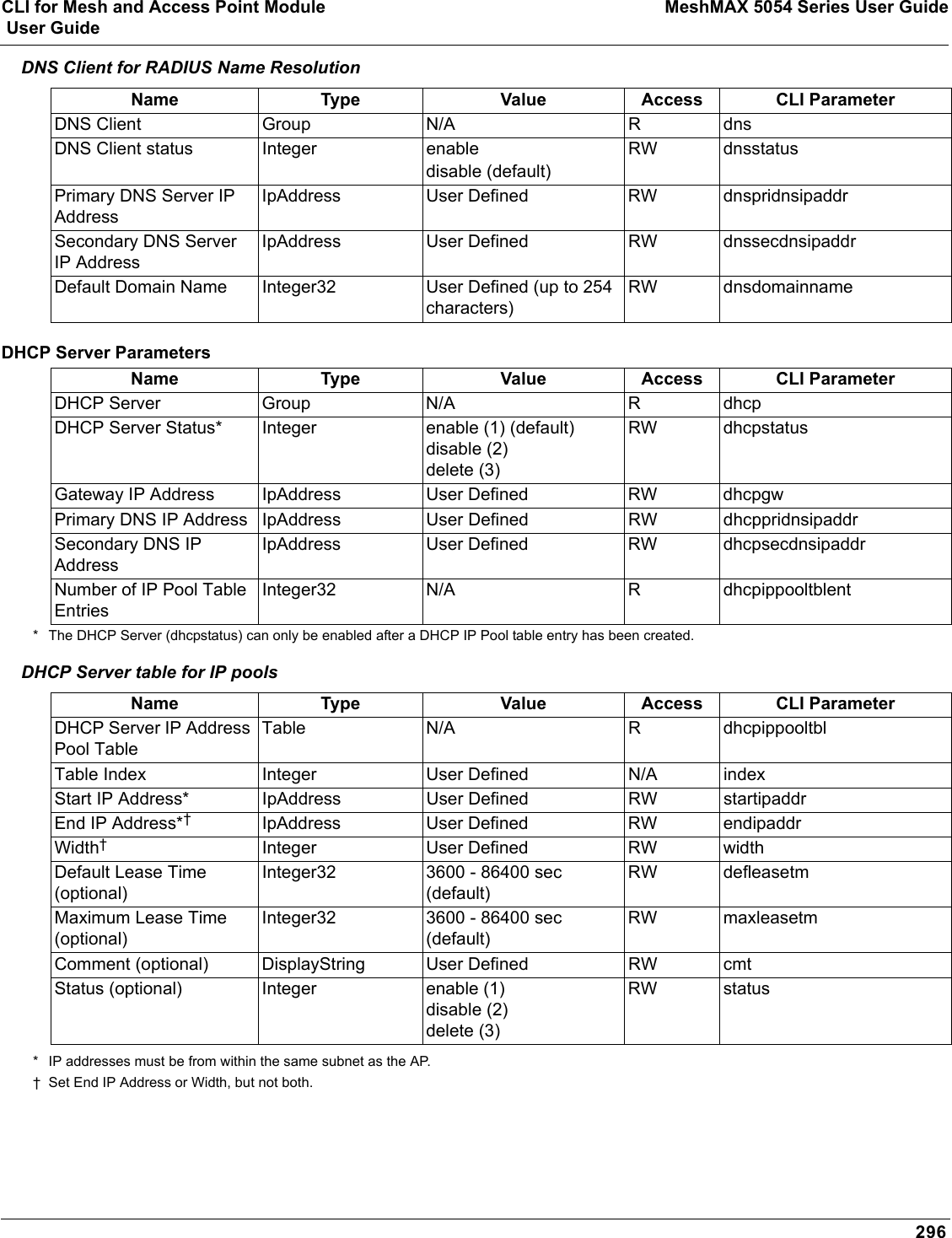
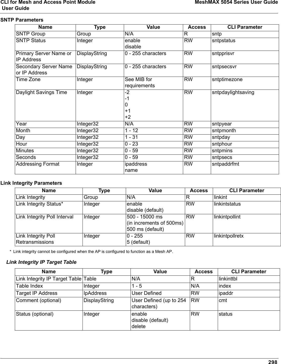
![CLI for Mesh and Access Point Module MeshMAX 5054 Series User Guide User Guide281Other Network SettingsThere are other configuration settings that you may want to set for the AP. Some of them are listed below. •Configure the AP as a DHCP Server•Configure the DNS Client•Configure DHCP Relay and Configure DHCP Relay Servers•Maintain Client Connections using Link Integrity•Change Wireless Interface Settings•Set Ethernet Speed and Transmission Mode•Set Interface Management Services•Configure Wireless Distribution System•Configure MAC Access Control•Set RADIUS Parameters•Set Rogue Scan Parameters•Set Hardware Configuration Reset Parameters•Set VLAN/SSID Parameters•Set Security Profile ParametersNOTE: See Advanced Configuration for more information on these settings.Configure the AP as a DHCP ServerNOTE: You must have at least one entry in the DHCP Server IP Address Pool Table before you can set the DHCP Server Status to Enable.[Device-Name]>set dhcpstatus disable [Device-Name]>set dhcpippooltbl 0 startipaddr <start ip address> endipaddr <end ip address> [Device-Name]>set dhcpgw <gateway ip address>[Device-Name]>set dhcppridnsipaddr <primary dns ip address>[Device-Name]>set dhcpsecdnsipaddr <secondary dns ip address> [Device-Name]>set dhcpstatus enable[Device-Name]>reboot 0CAUTION: Before enabling this feature, confirm that the IP address pools you have configured are valid addresses on the network and do not overlap the addresses assigned by any other DHCP server on the network. Enabling this feature with incorrect address pools will cause problems on your network.Configure the DNS Client[Device-Name]>set dnsstatus enable [Device-Name]>set dnsprisvripaddr <IP address of primary DNS server> [Device-Name]>set dnssecsvripaddr <IP address of secondary DNS server> [Device-Name]>set dnsdomainname <default domain name>[Device-Name]>show dnsFigure B-14 Results of “show dns” CLI command](https://usermanual.wiki/Proxim-Wireless/MESHMAXMP11R.Users-Manual-2-part-2/User-Guide-1030887-Page-133.png)
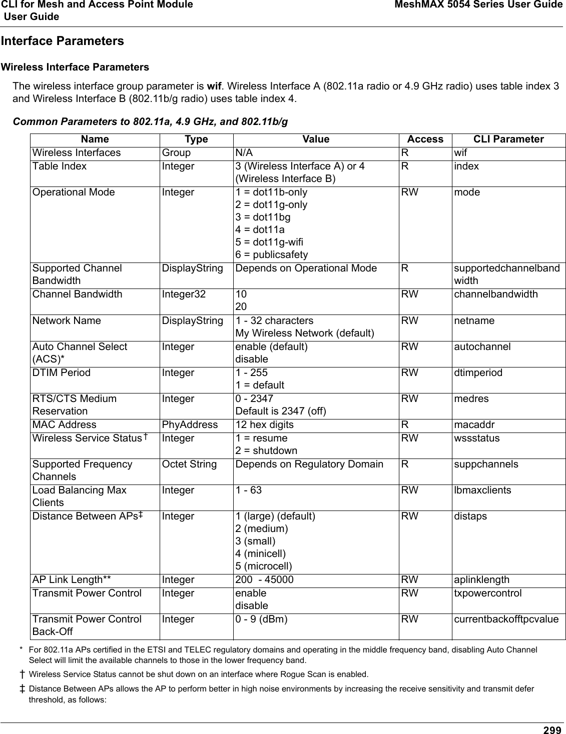
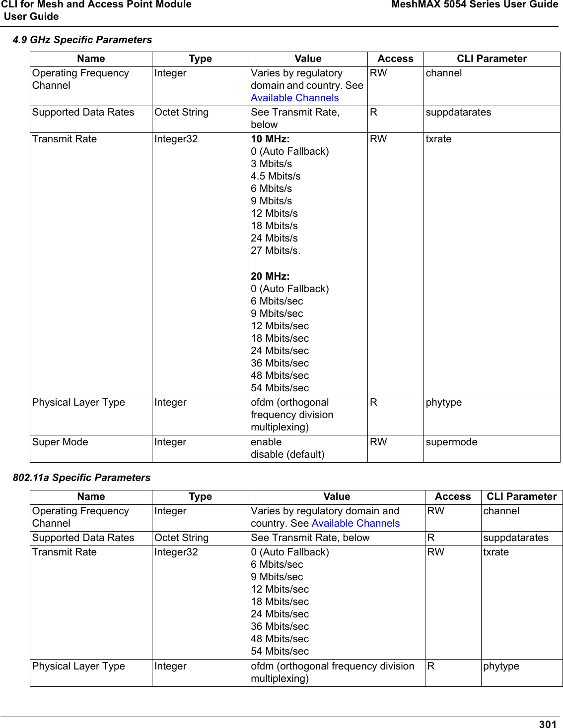
![CLI for Mesh and Access Point Module MeshMAX 5054 Series User Guide User Guide282Configure DHCP RelayPerform the following command to enable or disable DHCP Relay Agent Status.NOTE: You must have at least one entry in the DHCP Relay Server Table before you can set the DHCP Relay Status to Enable.[Device-Name]>set dhcprelaystatus enableConfigure DHCP Relay ServersPerform the following command to configure and enable a DHCP Relay Server. The AP allows the configuration of a maximum of 10 server settings in the DHCP Relay Agents server table.[Device-Name]>set dhcprlyindex 1 dhcprlyipaddr <ip address> dhcprlycmt <comment> dhcprlystatus 1 (1 to enable, 2 to disable, 3 to delete, 4 to create)Maintain Client Connections using Link Integrity[Device-Name]>show linkinttbl (this shows the current links)[Device-Name]>set linkinttbl <1–5 (depending on what table row you wish to address)> ipaddr <ip address of the host computer you want to check>[Device-Name]>set linkintpollint <the interval between link integrity checks>[Device-Name]>set linkintpollretx <number of times to retransmit before considering the link down>[Device-Name]>set linkintstatus enable[Device-Name]>show linkinttbl (to confirm new settings)[Device-Name]>reboot 0Change Wireless Interface Settings See Interfaces for information on the parameters listed below. The AP uses index 3 for Wireless Interface A (802.11a radio or 4.9 GHz radio) and index 4 for Wireless Interface B (802.11b/g radio).Operational Mode[Device-Name]>set wif <index> mode <see table>Autochannel Select (ACS)ACS is enabled by default. Reboot after disabling or enabling ACS.[Device-Name]>set wif <index> autochannel <enable/disable>[Device-Name]>reboot 0Mode Operational Mode1 dot11b-only2 dot11g-only3 dot11bg4 dot11a-only5 dot11g-wifi6 publicsafety](https://usermanual.wiki/Proxim-Wireless/MESHMAXMP11R.Users-Manual-2-part-2/User-Guide-1030887-Page-134.png)
![CLI for Mesh and Access Point Module MeshMAX 5054 Series User Guide User Guide283Enable/Disable Closed System[Device-Name]>set wif <index> closedsys <enable/disable>Shutdown/Resume Wireless Service[Device-Name]>set wif <index> wssstatus <1 (resume)/2 (shutdown)>Set Load Balancing Maximum Number of Clients[Device-Name]>set wif <index> lbmaxclients <1–63>Set the Multicast Rate (802.11a or 4.9 GHz)[Device-Name]>set wif 3 multrate <6, 12, 24 (Mbits/sec)>Set the Multicast Rate (802.11b/g)[Device-Name]>set wif 4 multrate <1, 2, 5.5, 11 (Mbits/sec)>Enable/Disable Super Mode (802.11a/g only)[Device-Name]>set wif <index> supermode <enable/disable>Set the Distance Between APs [Device-Name]>set wif <index> distaps <1–5> (see below)[Device-Name]>reboot 0Set Ethernet Speed and Transmission Mode[Device-Name]>set etherspeed <value> (see below)[Device-Name]>reboot 0Value Distance Between APs1 Large2Medium3Small4Mini5MicroEthernet Speed and Transmission ModeValue10 Mbits/sec - half duplex 10halfduplex10 Mbits/sec - full duplex 10fullduplex10 Mbits/sec - auto duplex 10autoduplex](https://usermanual.wiki/Proxim-Wireless/MESHMAXMP11R.Users-Manual-2-part-2/User-Guide-1030887-Page-135.png)
![CLI for Mesh and Access Point Module MeshMAX 5054 Series User Guide User Guide284Set Interface Management ServicesEdit Management IP Access Table[Device-Name]>set mgmtipaccesstbl <index> ipaddr <IP address> ipmask <subnet mask>Configure Management Ports[Device-Name]>set snmpifbitmask <(see below)>[Device-Name]>set httpifbitmask <(see below)>[Device-Name]>set telifbitmask <(see below)>Choose from the following values: Set Communication Ports[Device-Name]>set httpport <HTTP port number (default is 80)>[Device-Name]>set telport <Telnet port number (default is 23)>Configure Secure Socket Layer (HTTPS)Enabling SSL and configuring a passphrase allows encrypted Secure Socket Layer communications to the AP through the HTTPS interface. [Device-Name]>set sslstatus <enable/disable>The user must change the SSL passphrase when uploading a new certificate/private key pair, which will have a corresponding passphrase.[Device-Name]>set sslpassphrase <SSL certificate passphrase>[Device-Name]>show http (to view all HTTP configuration information including SSL.)Set Telnet Session Timeouts[Device-Name]>set tellogintout <time in seconds between 1 and 300 (default is 30)>[Device-Name]>set telsessiontout <time in seconds between 1 and 36000 (default is 900)>100 Mbits/sec - half duplex 100halfduplex100 Mbits/sec - full duplex 100fullduplexAuto Speed - half duplex autohalfduplexAuto Speed - auto duplex autoautoduplex (default)Interface Bitmask Description0 or 2 = Disable (all interfaces) All management channels disabled1 or 3 = Ethernet only Ethernet only enabled4 or 6 = Wireless A only Wireless A only enabled8 or 10 = Wireless B only Wireless B only enabled12 = Wireless A and Wireless B Wireless A and Wireless B enabled13 or 15 = Enable all interfaces All management channels enabledEthernet Speed and Transmission ModeValue](https://usermanual.wiki/Proxim-Wireless/MESHMAXMP11R.Users-Manual-2-part-2/User-Guide-1030887-Page-136.png)
![CLI for Mesh and Access Point Module MeshMAX 5054 Series User Guide User Guide285Configure Serial Port InterfaceNOTE: To avoid unexpected performance issues, leave Flow Control at the default setting (none) unless you are sure what this setting should be.[Device-Name]>set serbaudrate <2400, 4800, 9600, 19200, 38400, 57600> [Device-Name]>set serflowctrl <none, xonxoff>[Device-Name]>show serial Figure B-15 Result of “show serial” CLI CommandConfigure Syslog[Device-Name]>set syslogpriority <1–7 (default is 6)> [Device-Name]>set syslogstatus <enable/disable>[Device-Name]>set sysloghbstatus <enable/disable> (default is disable)[Device-Name]>set sysloghbinterval <1–604800> (default is 900 seconds)[Device-Name]>set sysloghosttbl <index> ipaddr <ipaddress> cmt <comment> status <enable/disable>Configure Intra BSS[Device-Name]>set intrabssoptype <passthru (default)/block)> Configure Wireless Distribution SystemCreate/Enable WDS[Device-Name]>set wdstbl <Index> partnermacaddr <MAC Address> status enable Enable/Disable WDS[Device-Name]>set wdstbl <Index> status <enable/disable>NOTE: <Index> is 3.1–3.6 (Wireless A) or 4.1–4.6 (Wireless B). To determine the index, type show wdstbl at the prompt.NOTE: When WDS is enabled, spanning tree protocol is automatically enabled. It may be manually disabled. If Spanning Tree protocol is enabled by WDS and WDS is subsequently disabled, Spanning tree will remain enabled until it is manually disabled. See Spanning Tree Parameters.Configure MAC Access ControlSetup MAC (Address) Access Control[Device-Name]>set wifssidtbl <index> aclstatus enable/disable[Device-Name]>set macacloptype <passthru, block>[Device-Name]>reboot 0Add an Entry to the MAC Access Control Table[Device-Name]>set macacltbl 0 macaddr <MAC Address> status enable[Device-Name]>show macacltbl](https://usermanual.wiki/Proxim-Wireless/MESHMAXMP11R.Users-Manual-2-part-2/User-Guide-1030887-Page-137.png)
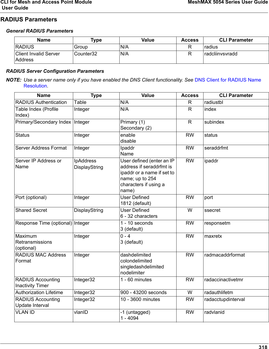
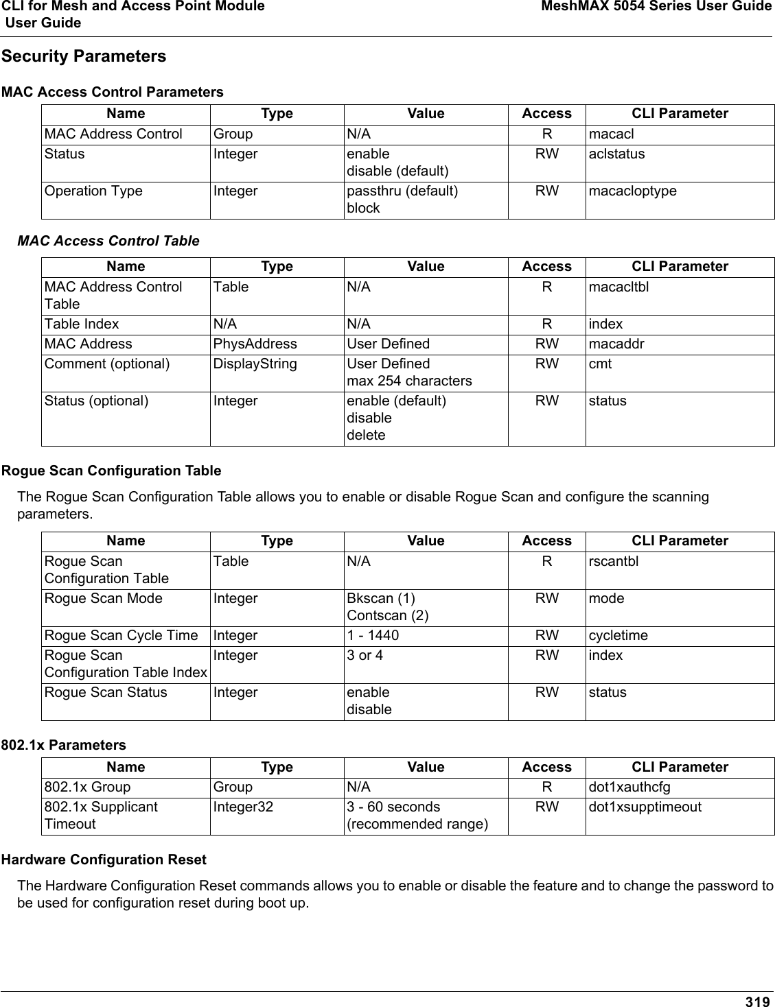
![CLI for Mesh and Access Point Module MeshMAX 5054 Series User Guide User Guide286Disable or Delete an Entry in the MAC Access Control Table[Device-Name]>set macacltbl <index> status <disable/delete>[Device-Name]>show macacltblNOTE: For larger networks that include multiple Access Points, you may prefer to maintain this list on a centralized location using the RADIUS parameters (see Set RADIUS Parameters).Set RADIUS ParametersConfigure RADIUS Authentication serversPerform the following command to configure a RADIUS Server and assign it to a VLAN. The RADIUS Server Profile index is specified by the index parameter and the subindex parameter specifies whether you are configuring a primary or secondary RADIUS server.[Device-Name]>set radiustbl <Index> profname <Profile Name> seraddrfmt <1 - IP Address 2 - Name> sernameorip <IP Address or Name> port <value> ssecret <value> responsetm <value> maxretx <value> acctupdtintrvl <value> macaddrfmt <value> authlifetm <value> radaccinactivetmr <value> vlanid <vlan id -1 to 4094> status enableNOTE: To create a new RADIUS profile, use 0 for <Index>.Examples of Configuring Primary and Secondary RADIUS Servers and Displaying the RADIUS ConfigurationPrimary server configuration:[Device-Name]>set radiustbl 1.1 profname "MAC Authentication" seraddrfmt 1 sernameorip 20.0.0.20 port 1812 ssecret public responsetm 3 maxretx 3 acctupdtintrvl 0 macaddrfmt 1 authlifetm 900 radaccinactivetmr 5 vlanid 22 status enableSecondary server configuration:[Device-Name]>set radiustbl 1.2 profname "MAC Authentication" seraddrfmt 1 sernameorip 20.0.0.30 port 1812 ssecret public responsetm 3 maxretx 3 acctupdtintrvl 0 macaddrfmt 1 authlifetm 900 radaccinactivetmr 5 vlanid 33 status enable[Device-Name]>show radiustblIndex : 1Primary/Backup : PrimaryProfile Name : MAC AuthenticationServer Status : notReadyServer Addressing Format : ipaddrIP Address/Host Name : 0.0.0.0Destination Port : 1812VLAN Identifier : -1MAC Address Format : dashdelimitedResponse Time : 3Maximum Retransmission : 3Authorization Lifetime : 0Accounting Update Interval : 0Accounting Inactivity Timer : 5Index : 1Primary/Backup : BackupProfile Name : MAC Authentication](https://usermanual.wiki/Proxim-Wireless/MESHMAXMP11R.Users-Manual-2-part-2/User-Guide-1030887-Page-138.png)
![CLI for Mesh and Access Point Module MeshMAX 5054 Series User Guide User Guide287Server Status : notReadyServer Addressing Format : ipaddrIP Address/Host Name : 0.0.0.0Destination Port : 1812VLAN Identifier : -1MAC Address Format : dashdelimitedResponse Time : 3Maximum Retransmission : 3...Index : 4Primary/Backup : BackupProfile Name : Management AccessServer Status : notReadyServer Addressing Format : ipaddrIP Address/Host Name : 0.0.0.0Destination Port : 1812VLAN Identifier : -1MAC Address Format : dashdelimitedResponse Time : 3Maximum Retransmission : 3Authorization Lifetime : 0Accounting Update Interval : 0Accounting Inactivity Timer : 5Figure B-16 Result of “showradiustbl” CLI CommandSet Rogue Scan ParametersPerform the following command to enable or disable Rogue Scan on a wireless interface and configure the scanning parameters.The cycletime parameter is only configured for background scanning mode.[Device-Name]>set rscantbl <3 or 4> mode <1 for background scanning, 2 for continuous scanning> cycletime <cycletime from 1–1440 minutes> status <enable/disable>NOTE: Rogue Scan cannot be enabled on a wireless interface when the Wireless Service Status on that interface is shutdown. First, resume service on the wireless interface.Set Hardware Configuration Reset ParametersThe Hardware Configuration Reset commands allows you to enable or disable the hardware reset functionality and to change the password to be used for configuration reset during boot up.To disable hardware configuration reset, enter: [Device-Name]>set hwconfigresetstatus disableTo enable hardware configuration reset, enter: [Device-Name]>set hwconfigresetstatus enableTo define the Configuration Reset Password to be used for configuration reset during boot up, enter the following command[Device-Name]>set configresetpasswd <password>](https://usermanual.wiki/Proxim-Wireless/MESHMAXMP11R.Users-Manual-2-part-2/User-Guide-1030887-Page-139.png)
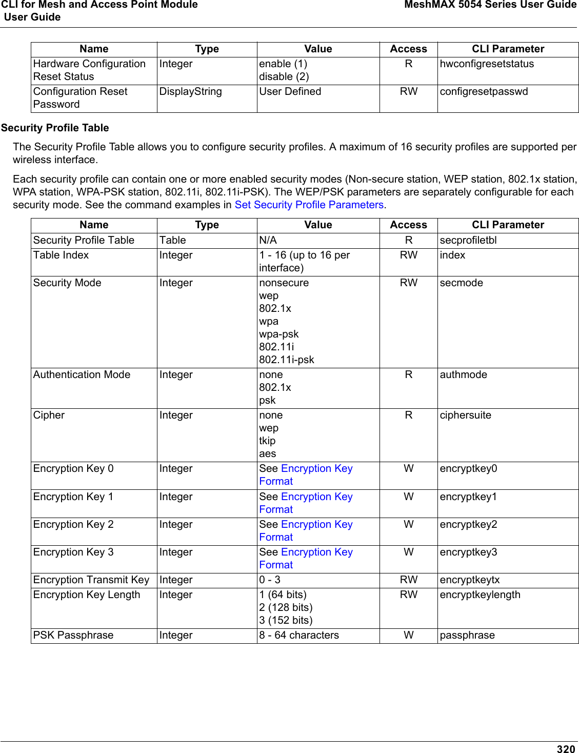
![CLI for Mesh and Access Point Module MeshMAX 5054 Series User Guide User Guide288It is important to safely store the NOTE: It is important to safely store the configuration reset password. If a user forgets the configuration reset password, the user will be unable to reset the AP to factory default configuration if the AP becomes inaccessible and the hardware configuration reset functionality is disable.Set VLAN/SSID ParametersEnable VLAN Management[Device-Name]>set vlanstatus enable[Device-Name]>set vlanmgmtid <1–4094>[Device-Name]>show wifssidtbl (to review your settings)[Device-Name]>reboot 0Disable VLAN Management[Device-Name]>set vlanstatus disable or[Device-Name]>set vlanmgmtid -1[Device-Name]>reboot 0Add a Entry to the WIFSSID Table[Device-Name]>set wifssidtbl <index> ssid <Network Name> vlanid <-1 (untagged) or 1–4094> status enableSet Security Profile ParametersConfigure a Security Profile with Non Secure Security Mode[Device-Name]>set secprofiletbl <index> secmode nonsecure status enableExample:[Device-Name]>set secprofiletbl 2 secmode nonsecure status enableConfigure a Security Profile with WEP Security Mode[Device-Name]>set secprofiletbl <index> secmode wep encryptkey<0-3> <value> encryptkeylength <value> encryptkeytx <value> status enableExample:[Device-Name]>set secprofiletbl 3 secmode wep encryptkey0 12345 encryptkeylength 1 encryptkeytx 0 status enableConfigure a Security Profile with 802.1x Security Mode[Device-Name]>set secprofiletbl <index> secmode 802.1x encryptkeylength <value> status enableExample:[Device-Name]>set secprofiletbl 4 secmode 802.1x encryptkeylength 1 status enableConfigure a Security Profile with WPA Security Mode[Device-Name]>set secprofiletbl <index> secmode wpa status enableExample:[Device-Name]>set secprofiletbl 5 secmode wpa status enable](https://usermanual.wiki/Proxim-Wireless/MESHMAXMP11R.Users-Manual-2-part-2/User-Guide-1030887-Page-140.png)
![CLI for Mesh and Access Point Module MeshMAX 5054 Series User Guide User Guide289Configure a Security Profile with WPA-PSK Security Mode[Device-Name]>set secprofiletbl <index> secmode wpa-psk passphrase <value> status enableExample:[Device-Name]>set secprofiletbl 6 secmode wpa-psk passphrase 12345678 status enableConfigure a Security Profile with 802.11i Security Mode[Device-Name]>set secprofiletbl <index> secmode 802.11i status enableExample:[Device-Name]>set secprofiletbl 7 secmode 802.11i status enableConfigure a Security Profile with 802.11i-PSK Security Mode[Device-Name]>set secprofiletbl <index> secmode 802.11i-psk passphrase <value> status enableExample:[Device-Name]>set secprofiletbl 8 secmode 802.11i-psk passphrase 12345678 status enable](https://usermanual.wiki/Proxim-Wireless/MESHMAXMP11R.Users-Manual-2-part-2/User-Guide-1030887-Page-141.png)


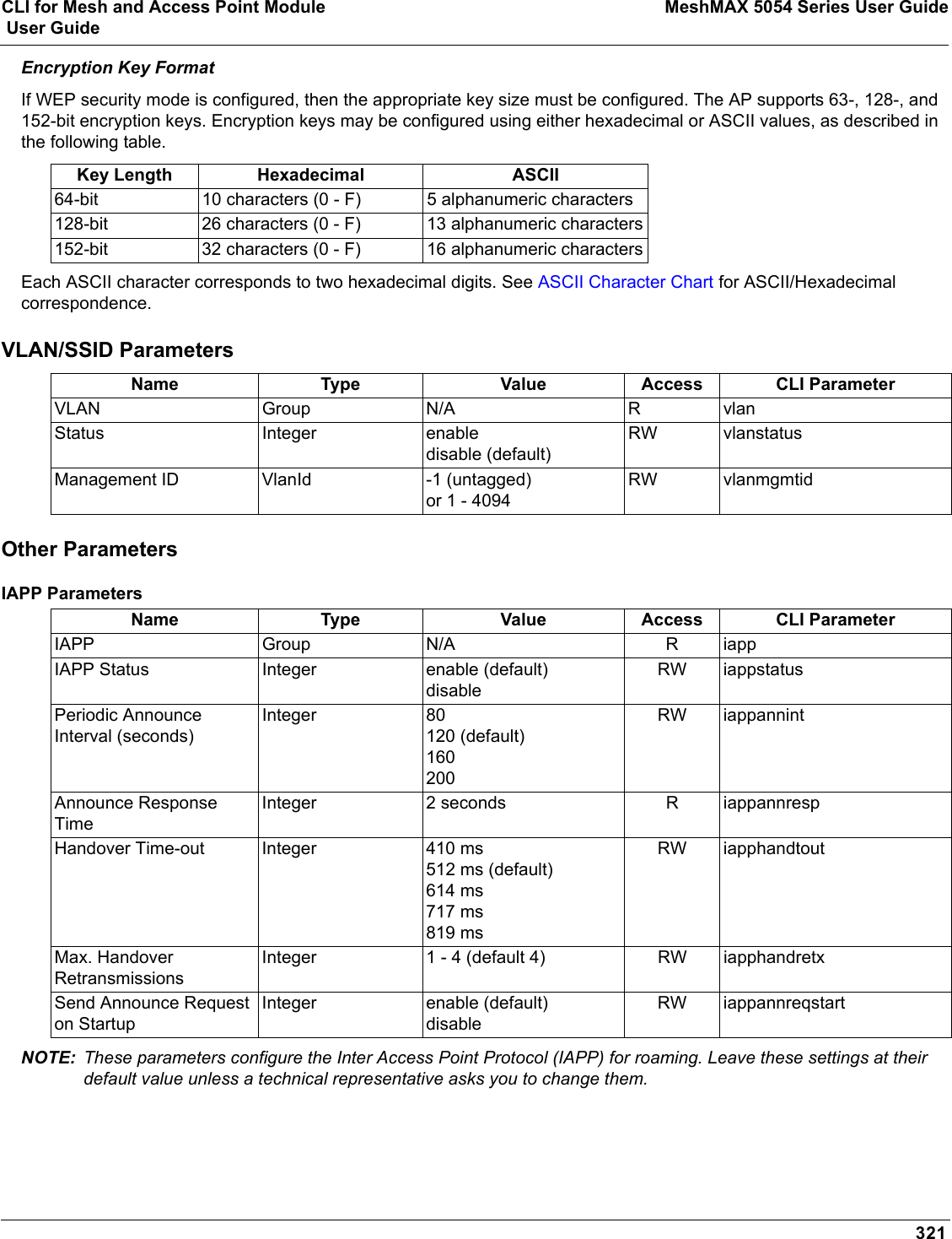
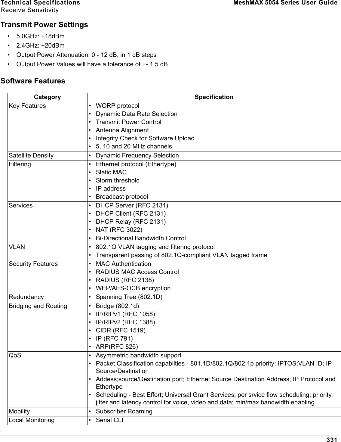
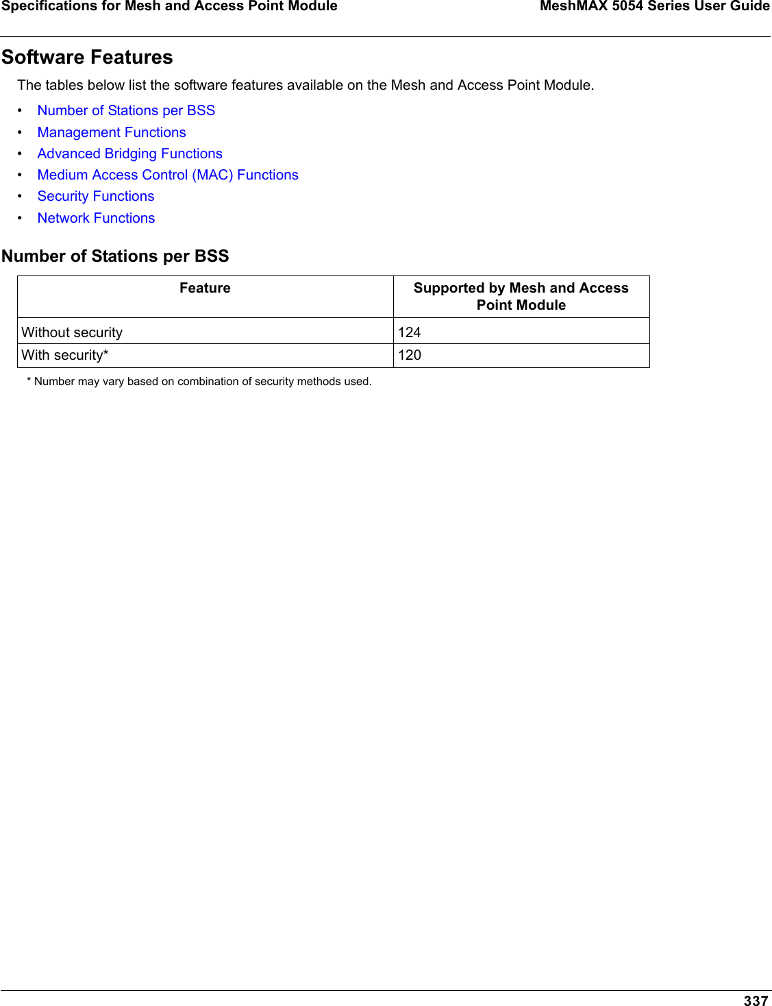
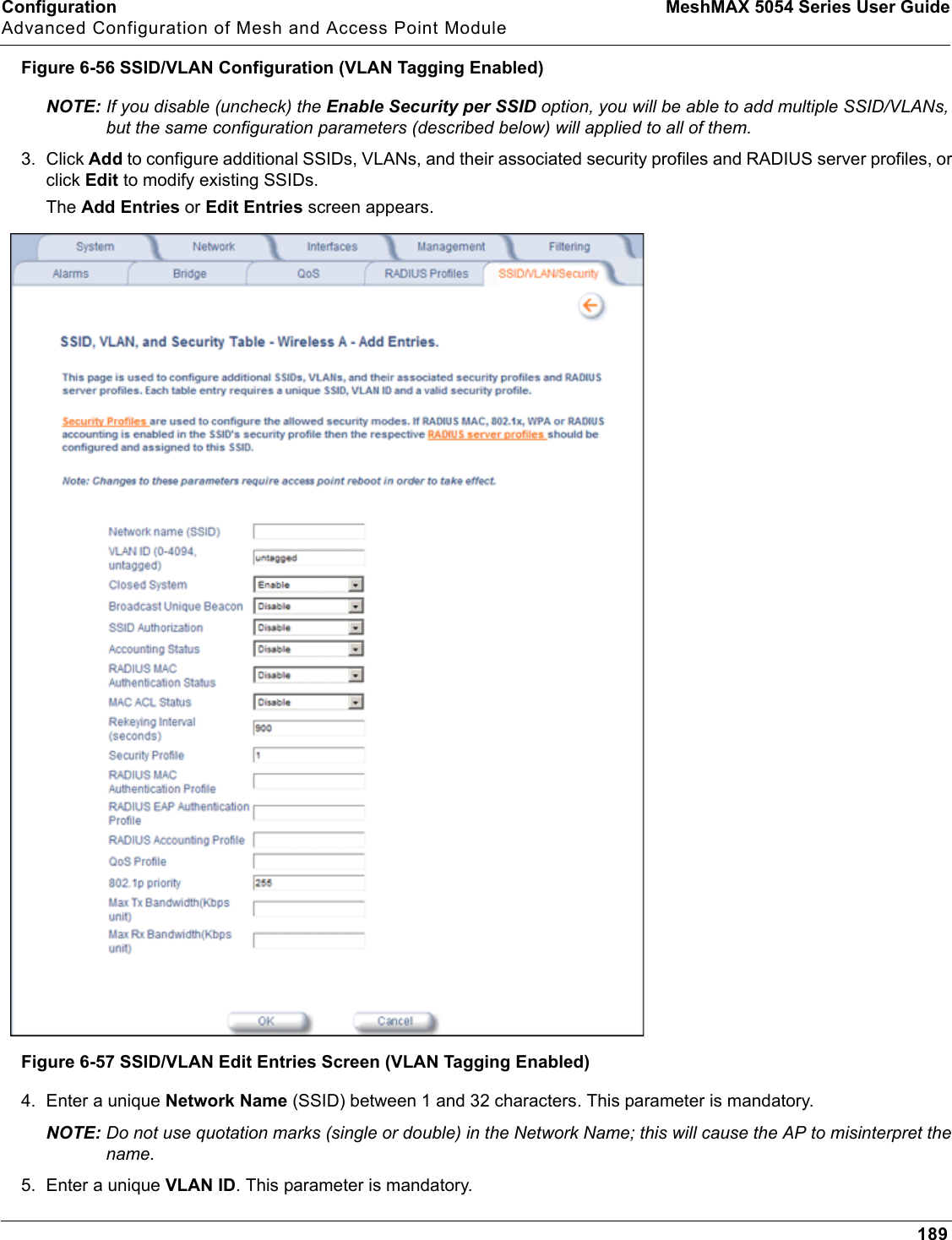
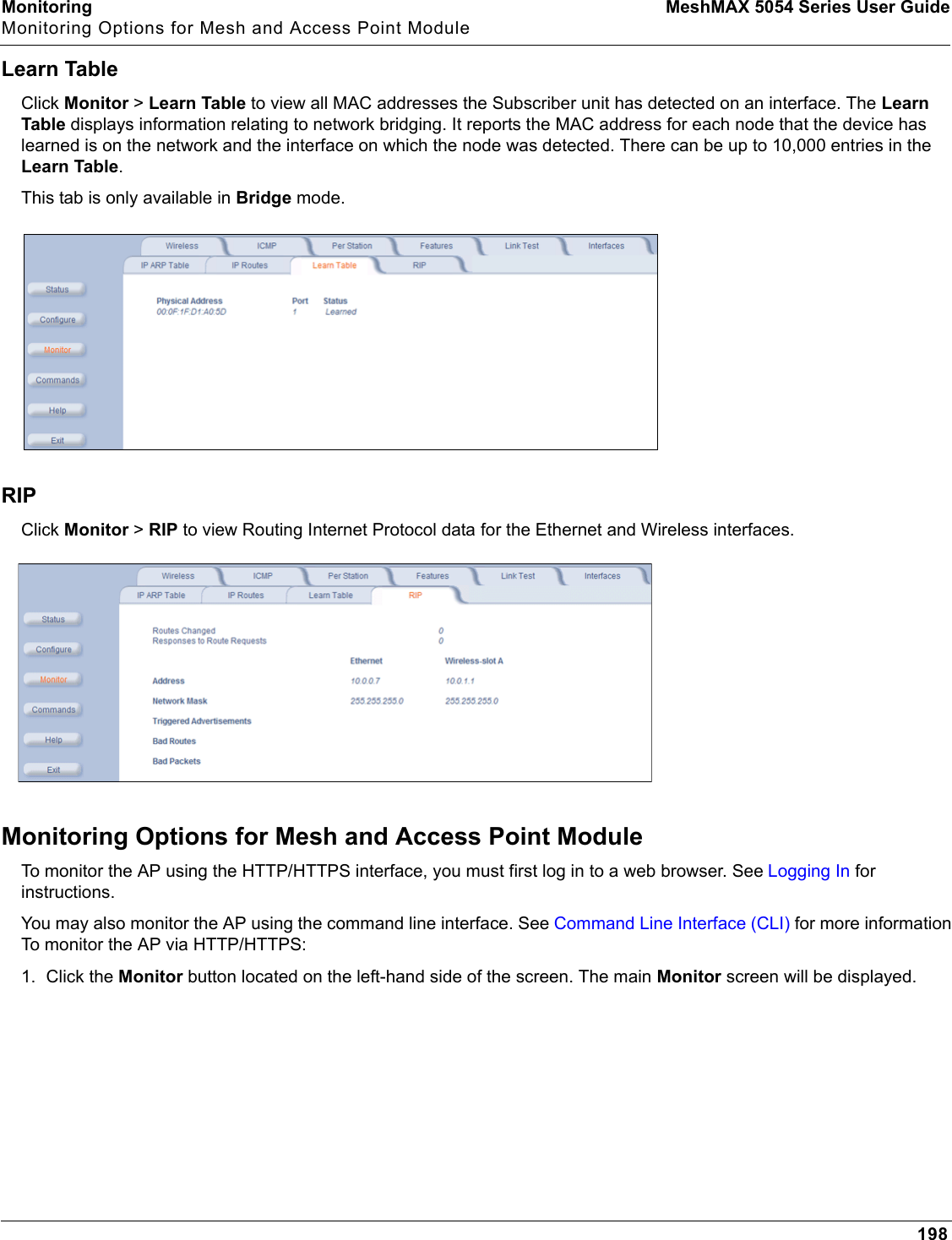
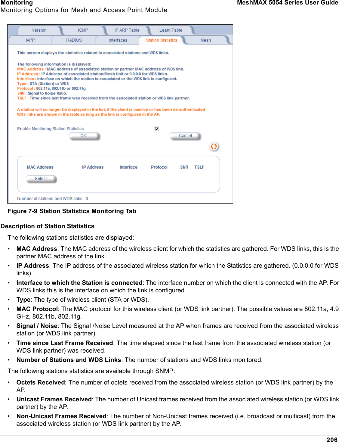
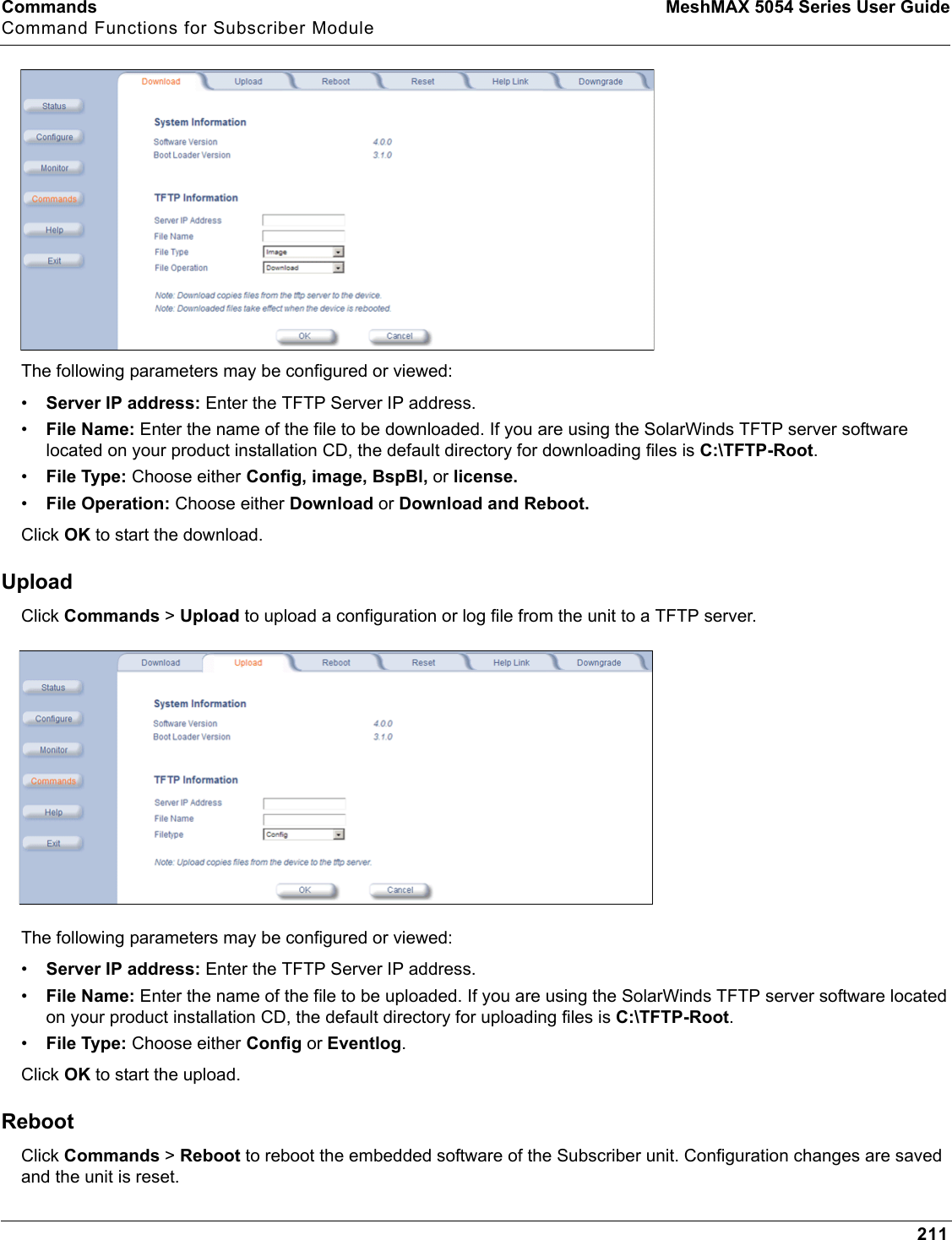
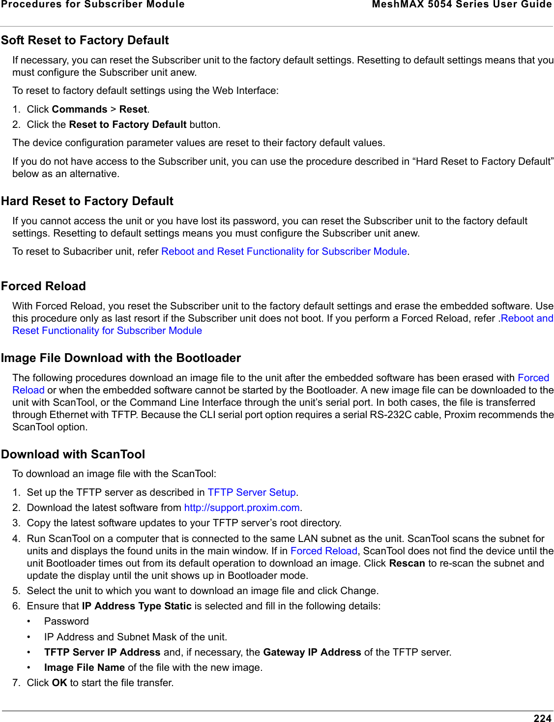
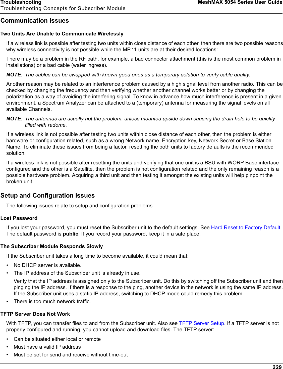
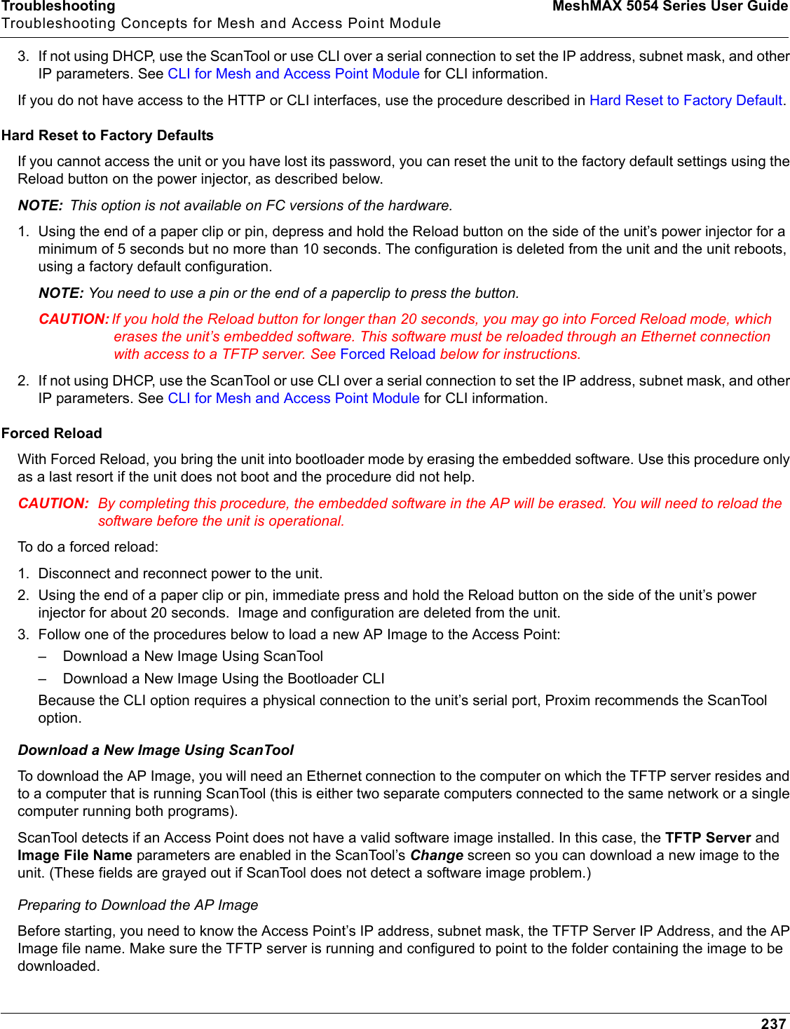
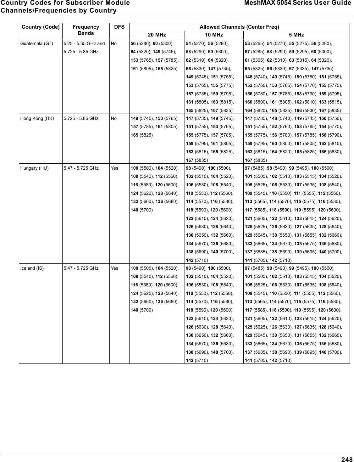
![327 MeshMAX 5054 Series User GuideCASCII Chart for Mesh and Access Point ModuleYou can configure WEP Encryption Keys in either Hexadecimal or ASCII format. Hexadecimal digits are 0-9 and A-F (not case sensitive). ASCII characters are 0-9, A-F, a-f (case sensitive), and punctuation marks. Each ASCII character corresponds to two hexadecimal digits.The table below lists the ASCII characters that you can use to configure WEP Encryption Keys. It also lists the Hexadecimal equivalent for each ASCII character.ASCII CharacterHex EquivalentASCIICharacterHexEquivalentASCIICharacterHexEquivalentASCII CharacterHexEquivalent!21939Q51i69"22:3AR52j6A#23;3BS53k6B$24<3CT54l6C%25=3DU55m6D&26>3EV56n6E'27?3FW57o6F(28@40X58p70)29A41Y59q71*2AB42Z5Ar72+2BC43[5Bs73,2CD44\5Ct74-2DE45]5Du75.2EF46^5Ev76/2FG47_5Fw77030H48`60x78131I49a61y79232J4Ab62z7A333K4Bc63{7B434L4Cd64|7C535M4De65}7D636N4Ef66~7E737O4Fg67838P50h68](https://usermanual.wiki/Proxim-Wireless/MESHMAXMP11R.Users-Manual-2-part-2/User-Guide-1030887-Page-179.png)