Powerwave Technologies 5JS0092 RF Repeater User Manual AR Repeaters Installation Guide
Powerwave Technologies Inc RF Repeater AR Repeaters Installation Guide
UserManual.wiki
>
Powerwave Technologies
>
5JS0092 User Manual
>
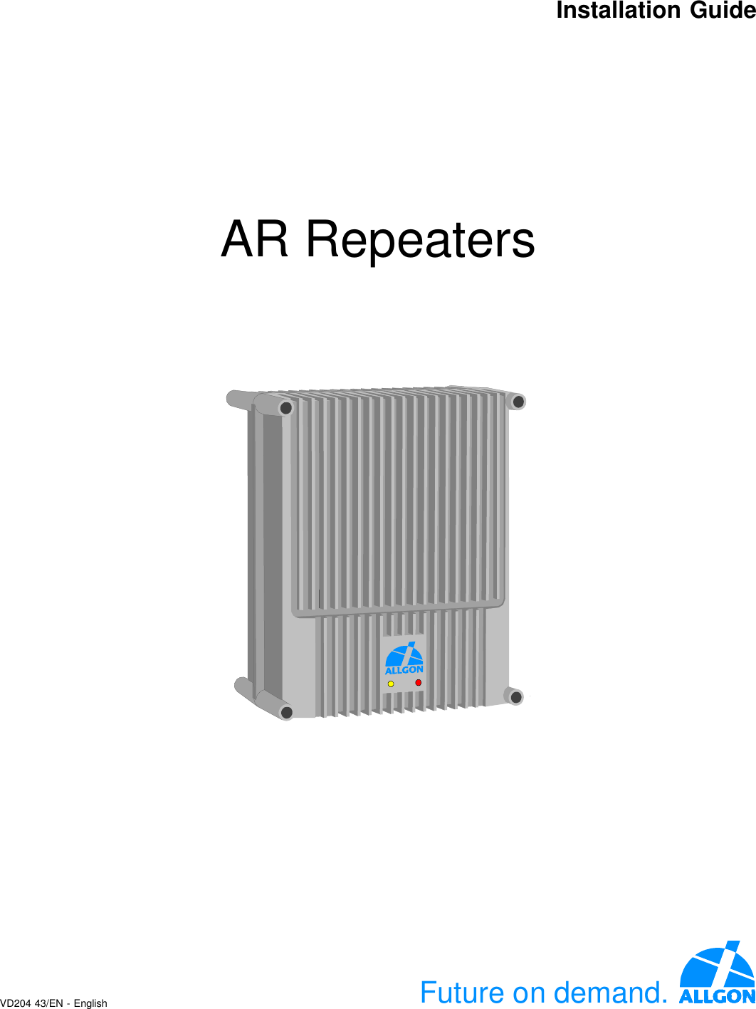
Installation Guide
Contents
1.
Users Manual
2.
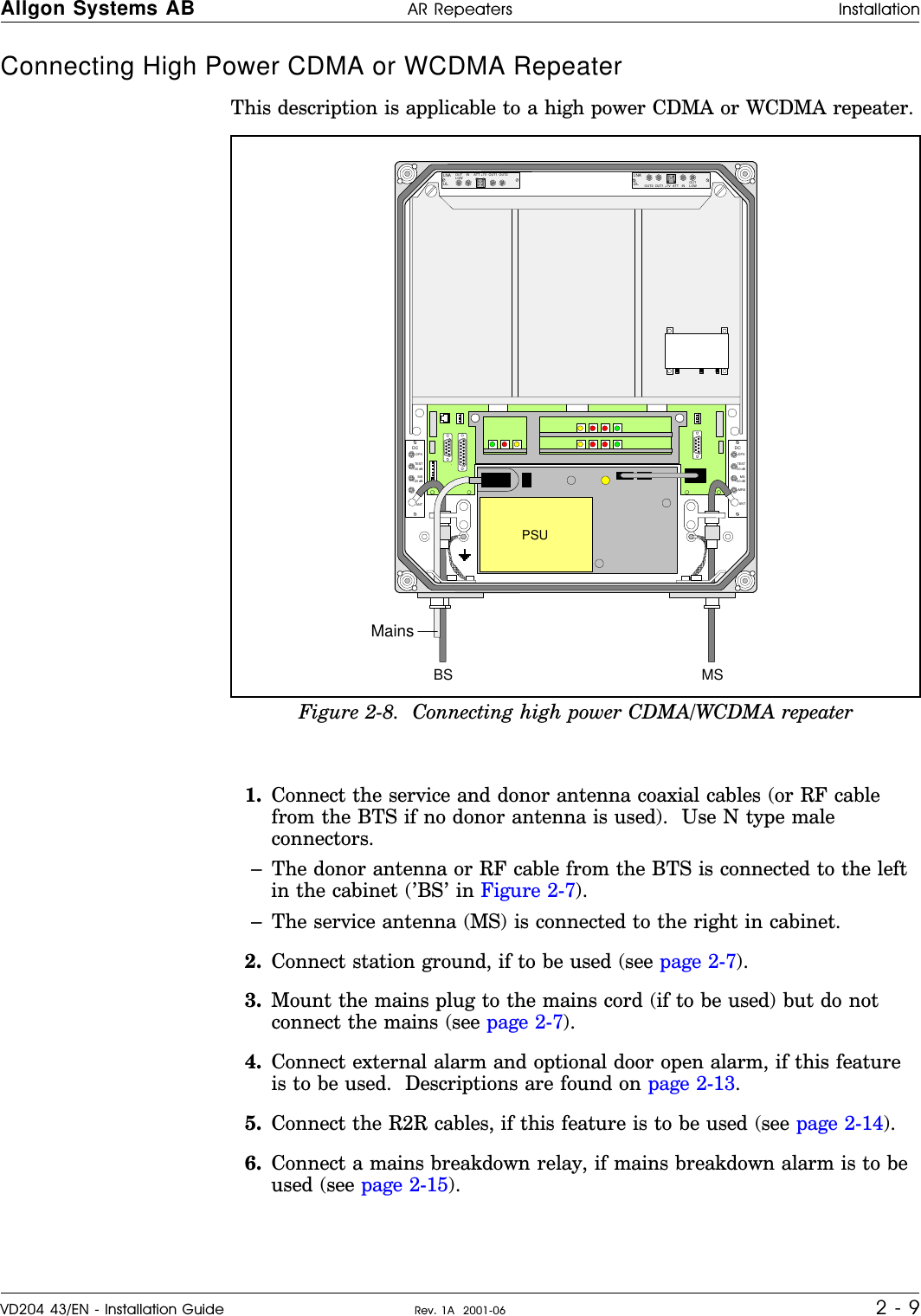
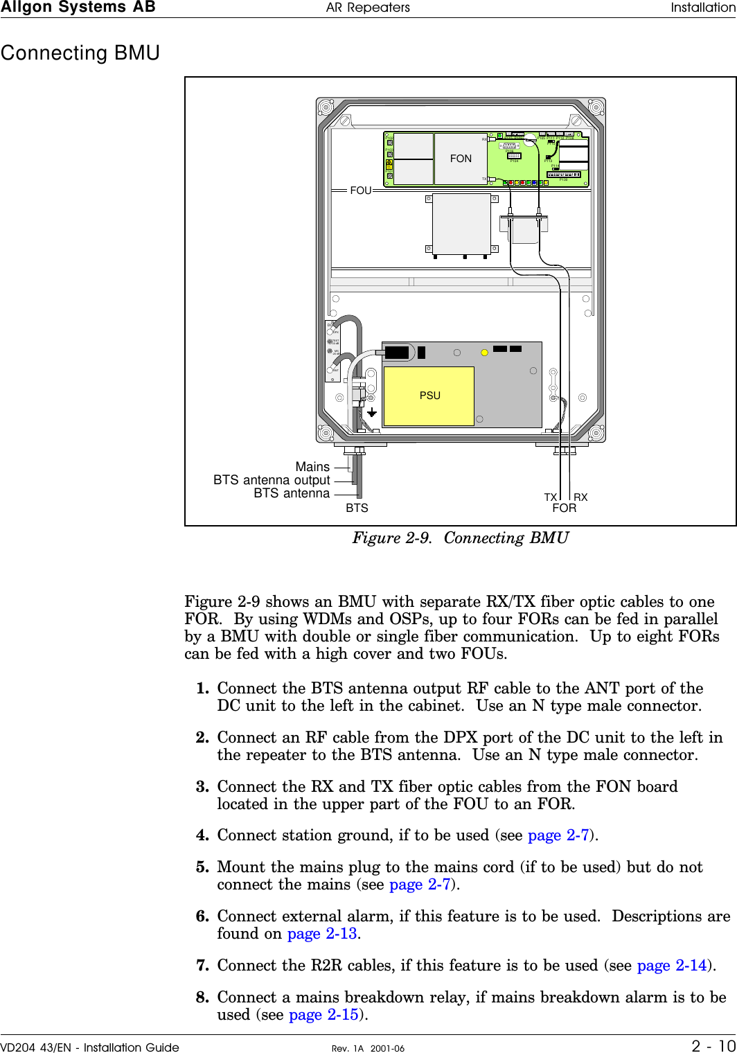
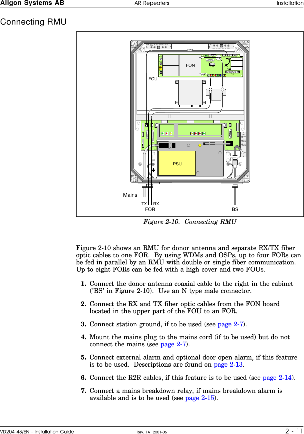
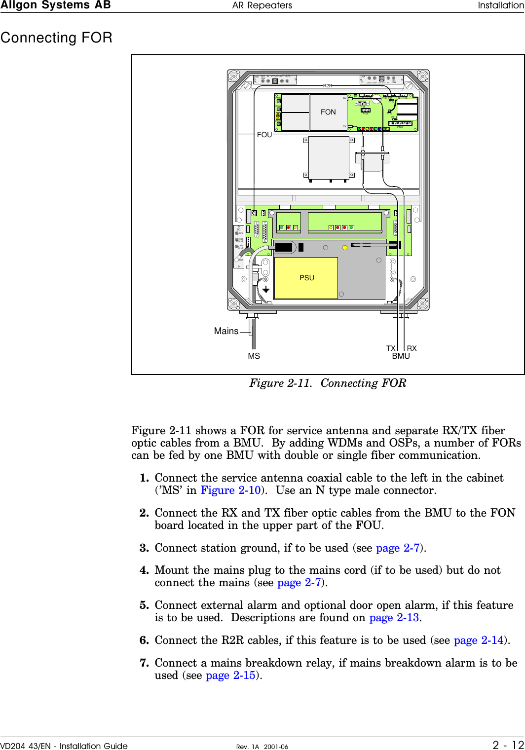
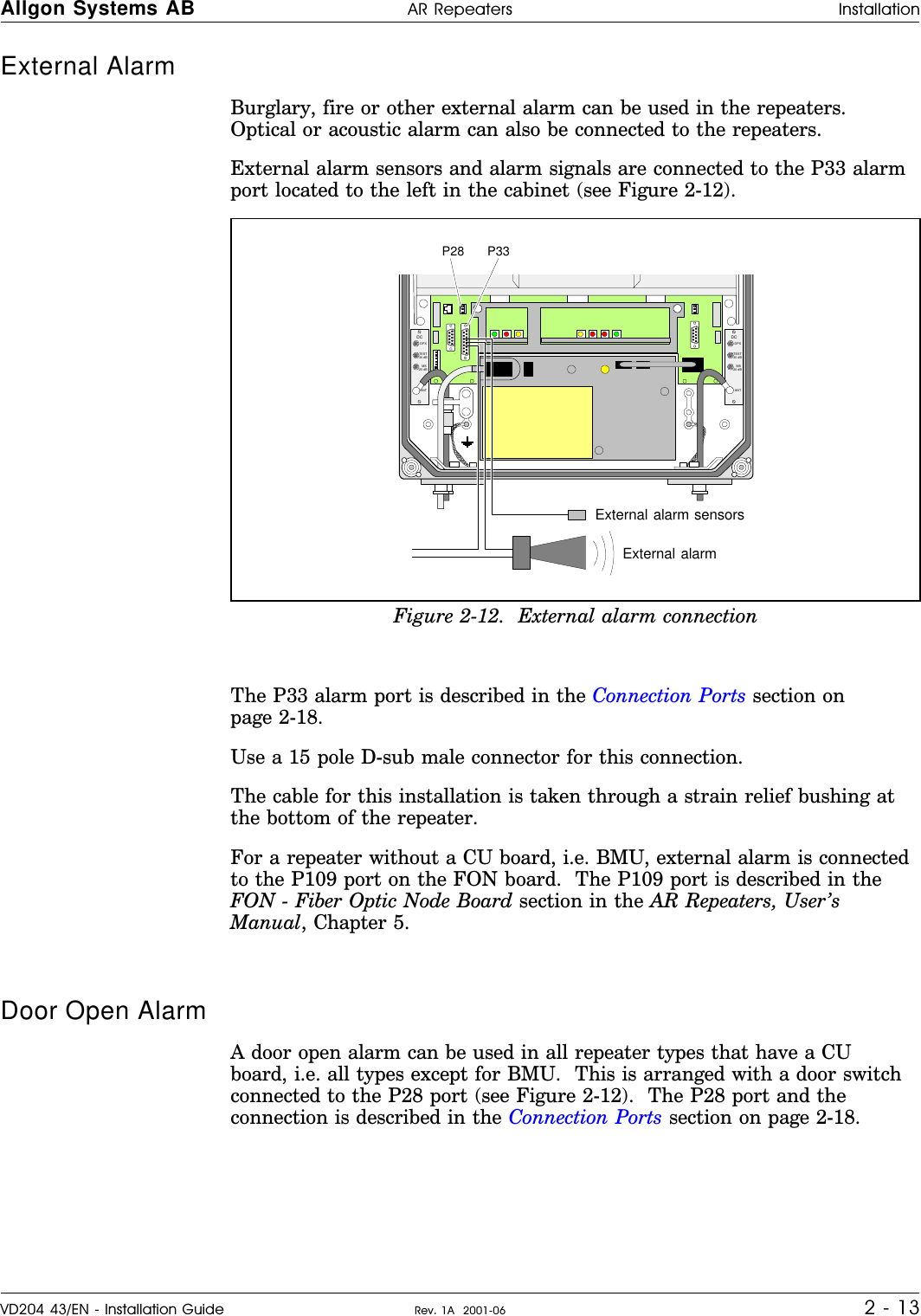
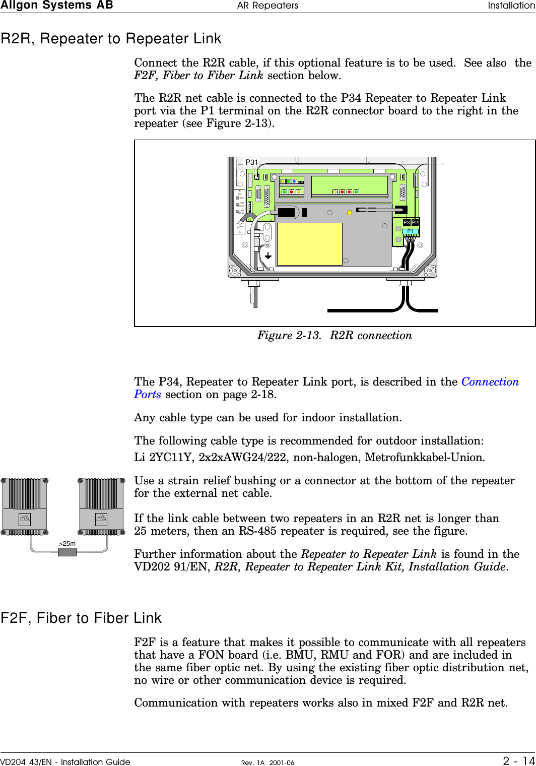
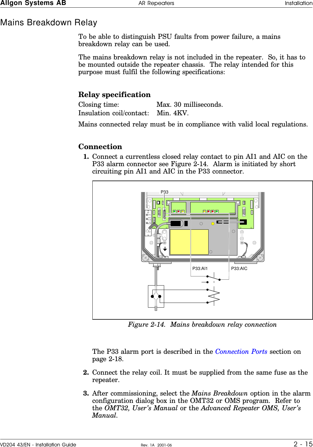
Installation Guide
Installation Guide
Navigation menu
Upload a User Manual
Namespaces
Wiki Guide
HTML
PDF
Info
Views
User Manual
Discussion / Help
Navigation