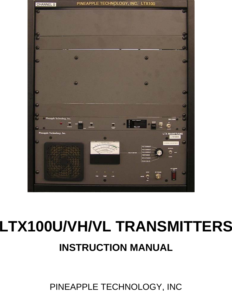
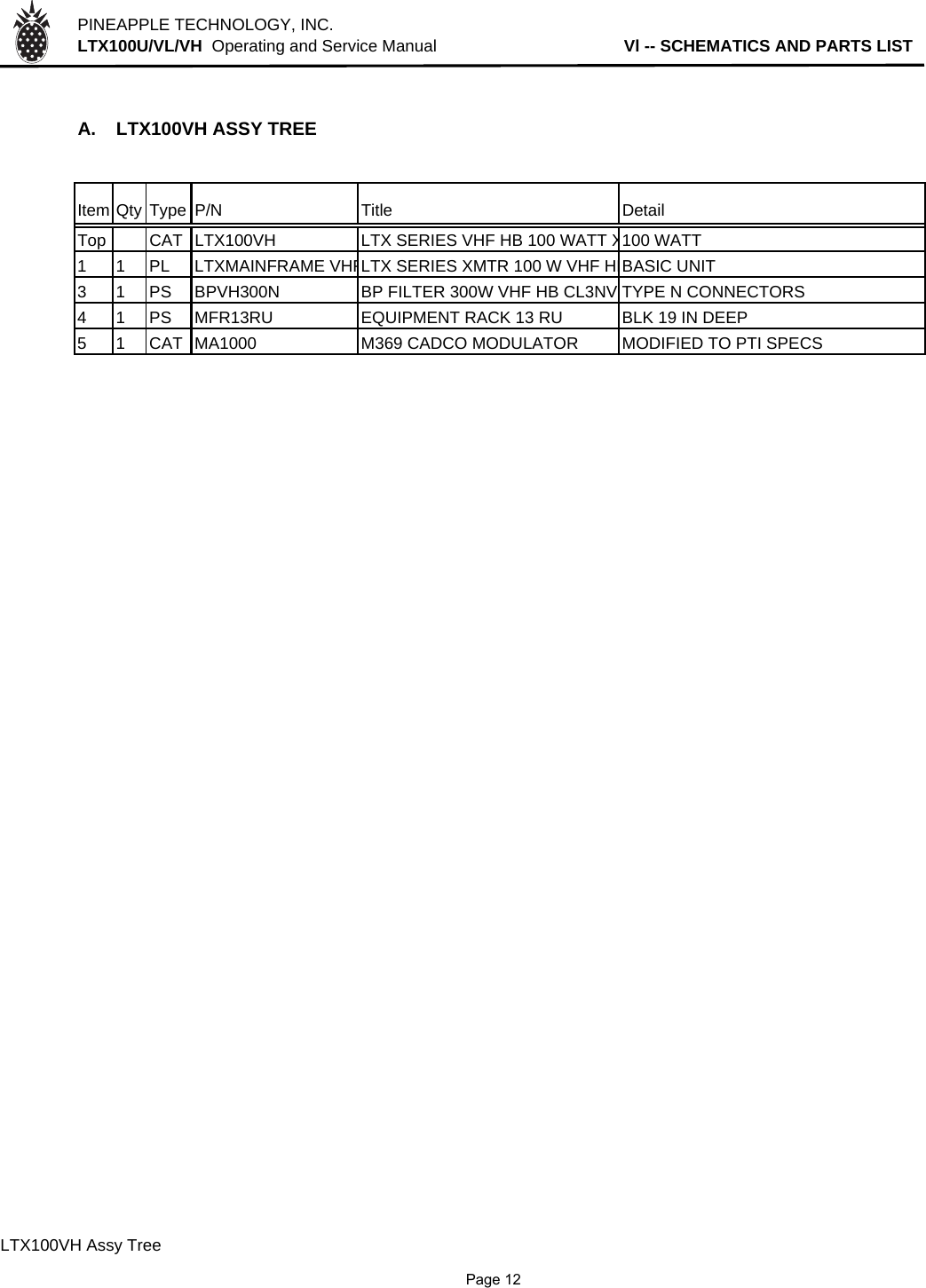
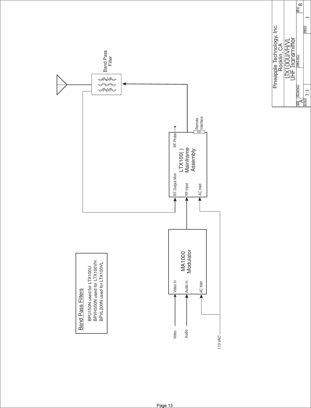
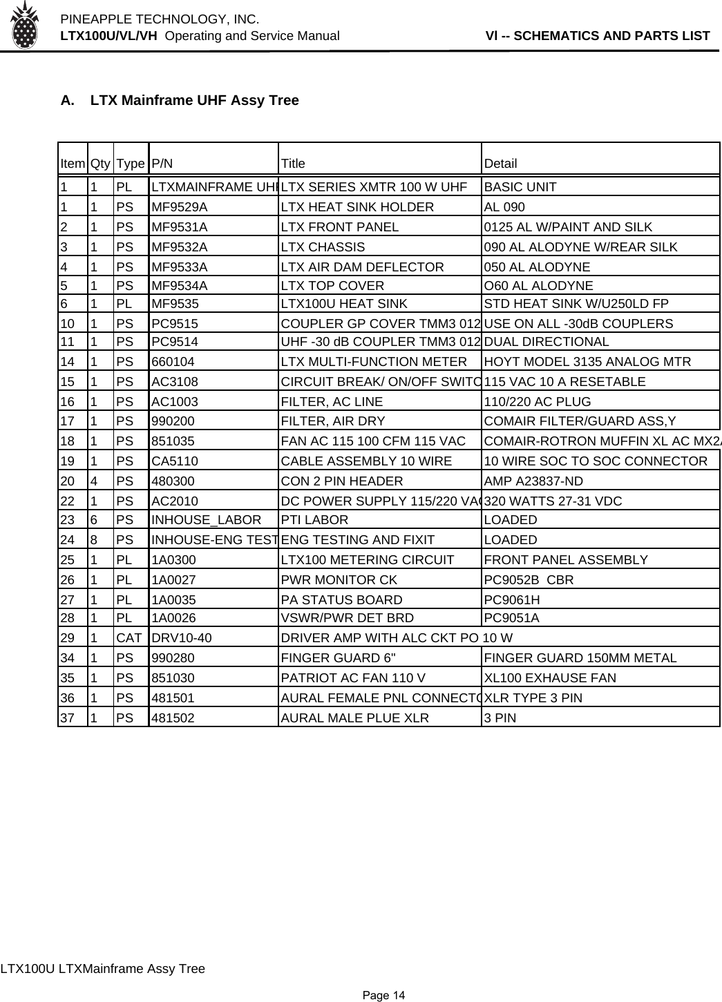
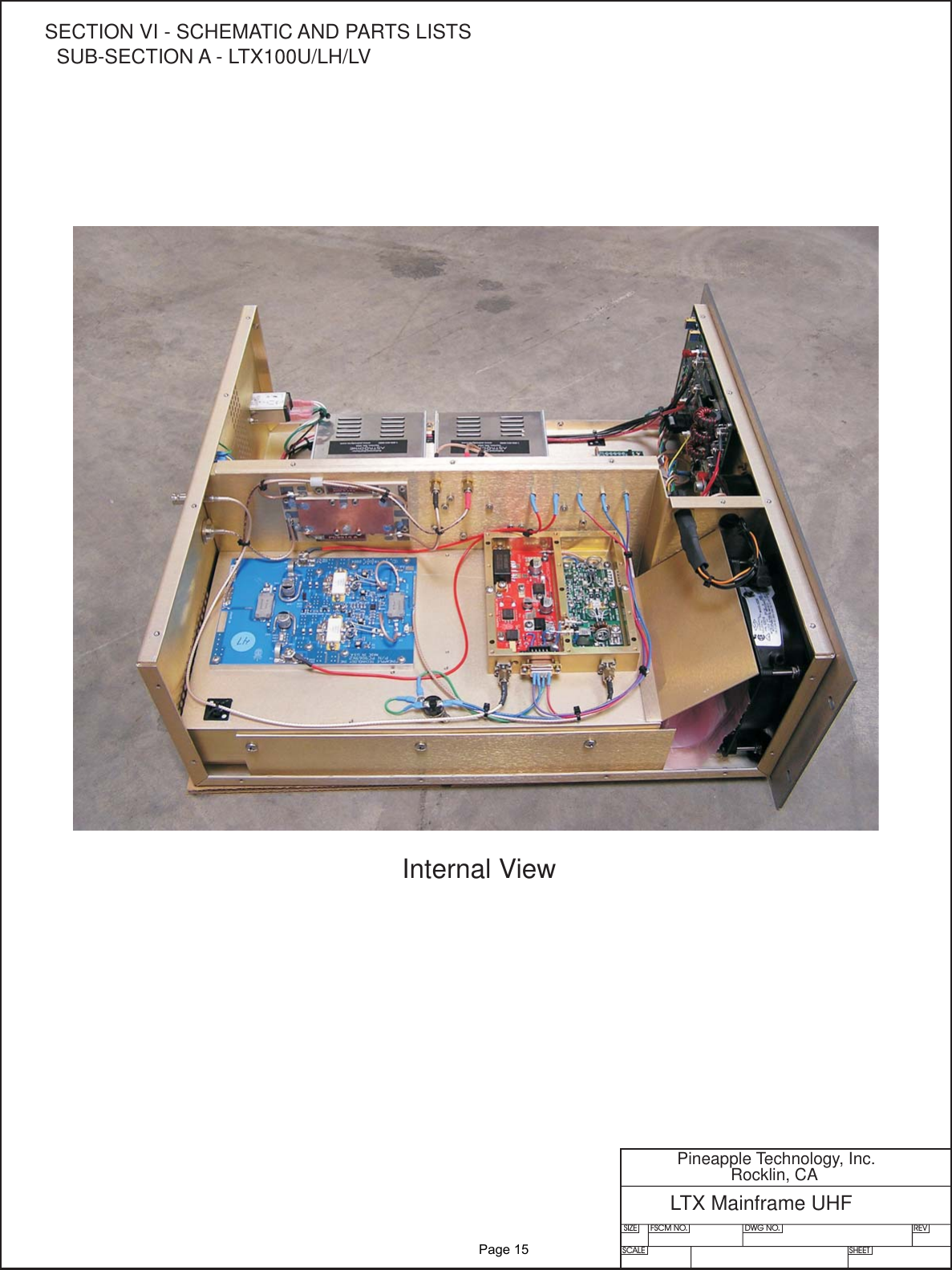
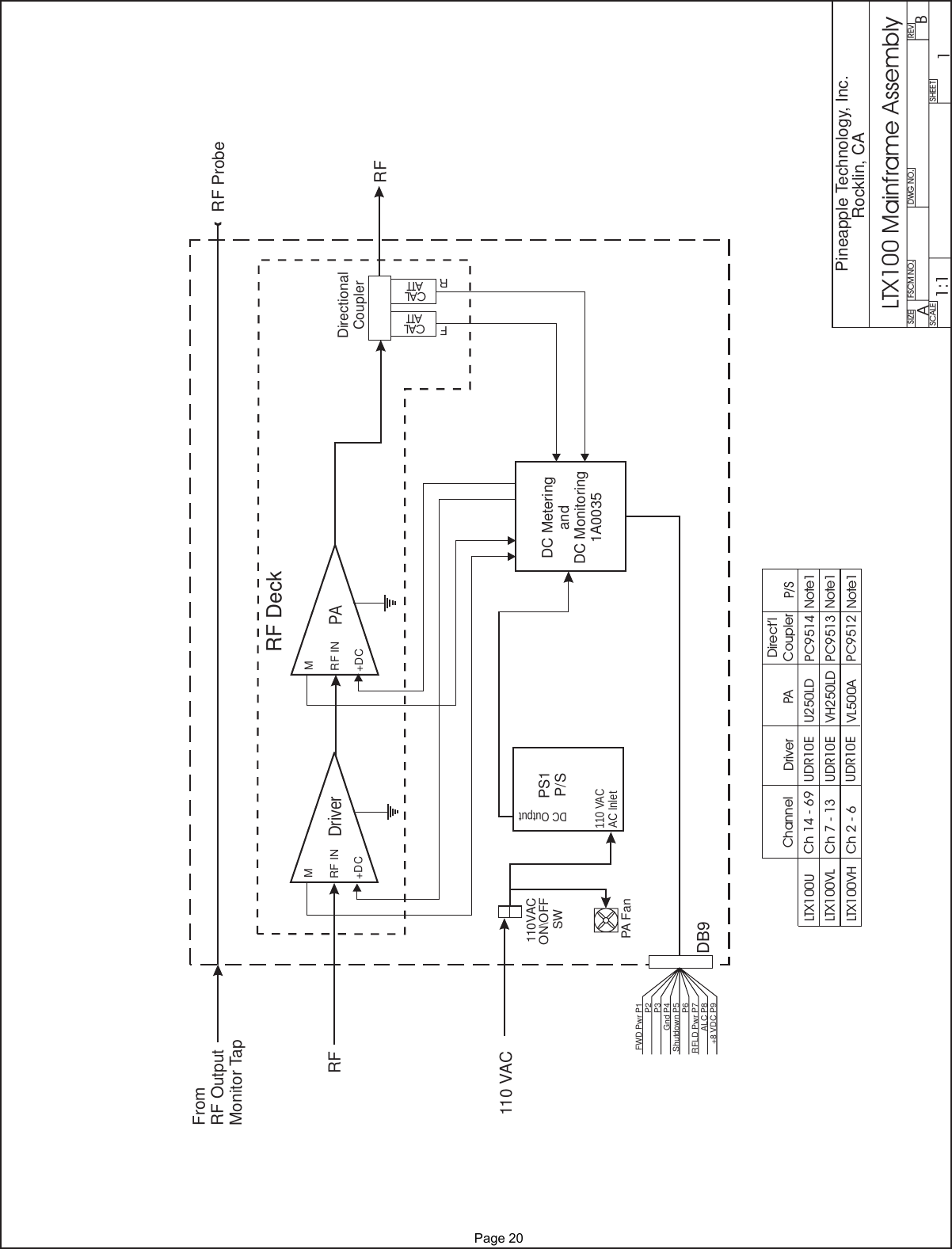
Pineapple Technology LTX100U 100 WATT TV ANALOG BROADCAST TRANSMITTER User Manual

Pineapple Technology, Inc. 100 WATT TV ANALOG BROADCAST TRANSMITTER

User Manual

LTX100U/VH/VL TRANSMITTERSINSTRUCTION MANUALPINEAPPLE TECHNOLOGY, INC
PINEAPPLE TECHNOLOGY, INC.  LTX100U/VH/VL  Operating and Service Manual TABLE OF CONTENTSSection l --- SAFETY NOTICES    …………………………………………………………………………2** READ THIS SECTION BEFORE INSTALLATON **Secton ll --- TRANSMITTER SPECIFICATIONS   …………………...…………………………………3Section lll --- TRANSMITTER INSTALLATION   ………………………………………………………5Section lV --- TRANSMITTER TURN-ON   ………………………………………………………………6Section V --- THEORY OF OPERATION   A. Introduction   ………………………………………………………………………………8B. MA1000 Modulator…………………………………………………………………………8C. LTX Mainframe Assembly ……………………………………………………………… 8D. BPU150/BPLV750/BPHV750 Broadband Filter…………………………………………9SECTION Vl --- SCHEMATIC AND PARTS LISTSA. LTX100U/VH/VL…………………………………………………………....................... 10B. LTX Mainframe Assembly…………………………………………………………………14C. BPU150/BPLV750/BPHV750 Broadband Filter…………………………………………21SECTION Vll --- RECOMMENDED ROUTINE MAINTENANCE   ……………………………………23SECTION Vlll --- ADJUSTMENTS AND TUNING   …………………………………………………… 24SECTION lX --- PROBLEM SOLVING / TROUBLESHOOTING   ……………………………………25SECTION X --- WARRANTY   …………………………………………………………………………… 27
Section ISafetyNotices
PINEAPPLE TECHNOLOGY, INC.  LTX100U/VH/VL  Operating and Service Manual l --- SAFETY NOTICESl ---SAFETY NOTICES** READ THIS SECTION BEFORE INSTALLATION **SEVERE ELECTRICAL SHOCK OR BURNS MAY OCCUR      IF THIS EQUIPMENT IS USED IMPROPERLY.NEVER WORK ON THIS EQUIPMENT ALONE. ALWAYS HAVE ANOTHER PERSON PRESENTWHILE WORKING ON ELECTRICAL CIRCUITS OR MOVING EQUIPMENT. COMMUNICATIONS                  TO EMERGENCY SERVICES SHOULD BE AVAILABLE AT ALL TIMES.   BEFORE CONNECTING THIS EQUIPMENT TO ANY AC ELECTRICAL SOURCE READ THE  SECTION ON INSTALLATION. ALL ELECTRICAL WIRING FOR THIS EQUIPMENT MUST BE    PERFORMED BY QUALIFIED ELECTRICIANS. ALL WIRING MUST BE COMPLIANT WITH                                                 LOCAL ELECTRICAL CODES.POWER AMPLIFIERS AND SUPPLIES ARE HEAVY. TO INSTALL THIS EQUIPMENT IN RACKS                         USE TWO (2) PERSONS TO AVOID POSSIBLE INJURIES.NEVER OPEN THE CABINET ENCLOSURE OR UNPLUG CABLES OR WIRES WHILE THIS                                             EQUIPMENT IS OPERATING.       ALL SERVICE WORK MUST BE PERFORMED BY QUALIFIED TECHNICIANS ONLY.   IF ONE IS NOT AVAILABLE LOCALLY, CONTACT PINEAPPLE TECHNOLOGY, INC. FOR                                                  A LIST IN YOUR AREA.               Page 2
Section IITransmitterSpecifications
THESE SPECIFICATIONS ARE SUBJECT TO CHANGE WITHOUT NOTICE.          PINEAPPLE TECHNOLOGY, INC.              LTX100U/VL/VH Operating and Service Manual                II – TRANSMITTER SPECIFICATIONS    II – LTX100U/VL/VH SPECIFICATIONS  OPERATING  Power Output …………………………  100 Watts P-Sync       5 Watts Aural                    RF Output Impedance…………………  50 ohms  Frequency Range     LTX100U……………………...470 – 806 MHz   LTX100VL…………………….CH 2 – CH 6  LTX100VH……………….……CH7 – CH13  Frequency Stability……………………  1 PPM or better  Harmonic and Spurious………………... -50 db   Power Consumption…………………… 500W maximum  AC Line Voltage………………………  85 – 120 VAC Single Phase           VIDEO PERFORMANCE  Visual Frequency Response…………… +/- 1 db across the TV channel -1.25 MHz to 4.75 Mhz                                                                   relative to visual carrier.  Differential Gain……………………………..< 7%  Low Frequency Linearity………………….. < 15%  Group Delay……………………………….. Meets FCC Part 73 Rule  Video Input Impedance……………………. 75 ohms  Video Input Level………………………….. 1 volt p-p  Variation of Output Power…………………. < 5%  Regulation of Output Power……………….. < 5% typical  Video Signal to Noise Ratio……………….. < 45 db un-weighted                   Page 3
THESE SPECIFICATIONS ARE SUBJECT TO CHANGE WITHOUT NOTICE.          PINEAPPLE TECHNOLOGY, INC.                LTX100U/VL/VH Operating and Service Manual                II – TRANSMITTER SPECIFICATIONS    AUDIO PERFORMANCE   Audio Response…………….…………. Meets FCC Pre-emphasis curve  Distortion…………………………………….< 1% THD  FM Noise…………………………............... < 50 dB or better  AM Noise……………………………………< 40 dB or better  AM Synchronous Noise……………………. < 40 dB typical   GENERAL   Operating Temperature…………………….. -10 to +35 Degrees Celsius Ambient                                +14 to +95 Degrees Fahrenheit Ambient  Altitude…………………………………….. 5,000 ft without additional cooling  Cooling Requirement………………………. Built in, except where noted        Connectors…………………………………..BNC Connector Input, N Connector Output  Weight………………………………………100 lbs  Dimensions Overall…………………………21” x  25” x 24”  (W x H x D) Standard                                                                                                       Page 4
Section IIITransmitterInstallation
PINEAPPLE TECHNOLOGY, INC.  LTX100U/LV/LH  Operating and Service Manual lll -- TRANSMITTER INSTALLATIONlll -- TRANSMITTER INSTALLATIONTo ensure long and reliable trouble-free service from the LTX100U/LV/LH transmitters the following stepsfor installation are recommended:1. MECHANICAL INSTALLATION: The LTX100U/LV/LH transmitters were designed to be installed in a building protected from the weather. The building should have a hard-surface floor such as concrete with a moisture barrier. This barrier could be pressure-treated wood sub flooring which could be anchored to the concrete and to the transmitter to make the installation earthquake resistant. For ease of operation and maintenance, the transmitter cabinet will need to be securely mounted to a raised structure at some appropriate distance above the floor.Provisions for air inlet and exhaust from the room must allow air flow with minimal obstruction.In the event that the room temperature exceeds 35º Celsius (95º F), cooling air must be providedso that the room temperature will not exceed 35 degrees Celsius under worse case conditions.Notice: This equipment is HEAVYand must be handled by professional movers with properequipment. Any damage caused by the installers is not covered under warranty. Check to ensurethat installing crews have proper insurance coverage.2. GROUNDING: Transmitter grounding is VERY IMPORTANT and must be done correctly forsafety and operational reasons. A typical installation may be done as follows:Use a heavy gauge wire such as 16 AWG stranded copper. The bonding between the transmitter and the ground rods must be good quality and protected from corrosion. The ground wires should run over the floor and be connected to the ground rods located outside the building. The wire should not go through the concrete floor but over and around it.3. AC WIRING: The LTX100U/LV/HV transmitters come with a three wire 110 VAC standard plug for connection to a 110 VAC electrical outlet. It is recommended that the electrical outlet be protected with its own separate breaker and used only for the transmitter.NOTICE: All wiring of this type, except for the actual connection to the AC plug,  must be done by a QUALIFIED ELECTRICIAN and must conform to LOCAL and NATIONAL wiring CODES.Consult with your electrician to ensure that the proper breaker size is selected for the main circuit.4. ANTENNA CONNECTION: The transmitters are equipped with an N connector for output power  to the transmit antenna and an F connector for connection from the receive antenna.               Page 5
Section IVTransmitterTurn-On
PINEAPPLE TECHNOLOGY, INC.  LTX100U/VL/VH  Operating and Service Manual lV -- TRANSMITTER TURN-ON PROCEDURElV --- TRANSMITTER TURN-ON PROCEDURE (Page 1 of 2)See the previous section on installation before proceeding with this section. Improper installation of thetransmitter can cause serious damage to the equipment or operating personnel and may voidmanufacturers warranty. Initial turn on and check out is very important for the broadcast engineer tolearn how to setup and operate the transmitter. Following these steps will ensure long and reliable operation:1. Check the transmitter output load or antenna for proper installation and connection to the transmitter.2. Inspect the transmitter front and back to check for broken items or lose fitting items. These mustbe replaced or properly secured before turning the transmitter on. Pay special attention to all RFconnectors including transmit coaxial cable and antenna. 3. Check the AC breaker and on/off switches to ensure that all are in the OFF position.4. Verify the switch on the power strip at the back of the cabinet and the power switch on the front of the LTX Mainframe are in the OFF position. Plug in the AC power cord to a nearby 110 AC electricalconnector with associated, appropriately sized, circuit breaker.5. On the MA1000 Modulator, turn the Output Power potentiometer fully counter clockwise to minimum.6. Turn-on the AC Power switch located on the power strip at the rear of the LTX100U/VL/VH cabinet. 7. Locate and turn on the front panel breaker found on the LTX Mainframe and set the XMTR switch to the ON position. MAKE THE FOLLOWING OBSERVATIONSMETER READINGS TYPICALDC SUPPLY VOLTAGE 32 VDCPA1 DRIVER CURRENT1.7 AMPS ± 20%PA2 FINAL CURRENT2.7 AMPS ± 20%PA3 FINAL CURRENT1.3 AMPS ± 20%RF OUTPUT POWER 10 TO 50%RFL'D POWER < 10%NOTE STATUS LIGHTSFAN GREENTEMP GREEN+DC GREENTHE FAN SHOULD BE MAKING SOME NOISE              Page 6
PINEAPPLE TECHNOLOGY, INC.  LTX100U/VL/VH  Operating and Service Manual lV -- TRANSMITTER TURN-ON PROCEDURElV --- TRANSMITTER TURN-ON PROCEDURE (Page 2 of 2)Note: Allow the LTX100U/VL/VH to warm up for at least one (1) hour before making the final adjustment.If transmitter is not warmed up, the output power will require re-adjustment to proper level when it is warm.8. Select the FWD Power setting on the rotary switch associated with the front panel meter on the LTX Mainframe assembly. Slowly adjust the Output Level setting on the MA1000 Modulator while observing the output power level on the front panel meter until the meter reading indicates 50% output power. At thispoint, check the reflected power indication on the LTX meter. The reading should be less than 5% if theoutput connection, cable and antenna have been previously verified to have a VSWR of less than 1.2:1.9. If the output level is stable at the 50% point for 5 or 10 minutes, it is OK to increase the drive to achievea reading of 100%. This is the output level set at the factory for your transmitter and is p-sync reading.RECORD AND RETAIN THE FOLLOWING OBSERVATIONS FOR FUTURE REVIEW IF NECESSARYMETER READINGS TYPICALDC SUPPLY VOLTAGE 32 VDCPA1 DRIVER CURRENT1.8 AMPS ± 20%PA2 FINAL CURRENT3.4 AMPS ± 20%PA3 FINAL CURRENT2.8 AMPS ± 20%RF OUTPUT POWER 90 TO 100%RFL'D POWER < 10%NOTE STATUS LIGHTSFAN GREENTEMP GREEN+DC GREEN10. Check the transmitter on-the-air signal with a monitor to ensure all is well and you're done.              Page 7
Section VTheoryofOperation
PINEAPPLE TECHNOLOGY, INC.  LTX100U/VL/VH  Operating and Service Manual                   V -- THEORY OF OPERATIONV --- THEORY OF OPERATION  (Page 1 of 2)A. INTRODUCTIONThe LTX100U/VL/VH series transmitters were designed to meet or exceed all FCC applicable specifications forTV broadcast equipment. Special attention was given to the selection of sub-assemblies and componentsto achieve maximum reliability and minimum down time. The construction of the LTX100U/VL/VH isBASIC and MODULAR with most components are field replaceable. Special emphasis was placed on"KEEPING IT SIMPLE" and returning to more traditional transmitter layouts and instrumentation.Refer to the LTX100U/VL/VH block diagram for an overview of the transmitter architecture. This will give the technician basic information needed to understand the operation of the transmitter and the function of each subassembly.SEE SECTION Vl.A  FOR PARTS LIST AND BLOCK DIAGRAM.B.  MA1000 Modulator/ExciterThe modulator/exciter is set up at the factory for the operating frequency (Channel) specified by thecustomer as shown on the appropriate FCC document including any appropriate offset.Refer to the Cadco user manual at the end of this manual for information on the modulator. C. LTX100( ) Mainframe Power AmplifierCabinet - The cabinet is constructed of heavy gauge steel and is very durable. This enclosure is painted black and is resistive to harsh environment. Standard 19 inch rack mounting. The LTX100( ) Mainframe is the power amplifier assembly that accepts the video and audio signal from the modulator/exciter and raises it up to the required output power which will be sent to theantenna.LTX100( ) Mainframe Assembly's internal sub-assemblies include the following:1. DC Power Supply2. RF Deck3. Status Monitoring (1A0035)4. Output Power Detector Board (1A0027)5. Reflected Power Detector (1A0029) and Shutdown Switch6. Metering and Monitoring Assembly (1A0300)              Page 8
PINEAPPLE TECHNOLOGY, INC.  LTX100U/VL/VH  Operating and Service Manual                   V -- THEORY OF OPERATIONV. THEORY OF OPERATION (CONTINUED)  (Page 2 of 2)D. BAND PASS FILTERSBPU150N - Used in the LTX100U UHF TransmitterBPVH300N - Used in the LTX100VH High VHF Band (Ch 7 - 13) TransmitterBPVL200N - Used in the LTC100VL High VHF Band (Ch 2 - 6) Transmitter These Band Pass filters were designed to meet FCC Certification requirements with minimum loss ofRF Power. Thy come tuned and tested to the operating frequency of the transmitterand should not be adjusted without proper equipment. Replacement filters are available asfrom Pineapple Technology, Inc. upon request.              Page 9
Section VISchematicandParts List
PINEAPPLE TECHNOLOGY, INC.  LTX100U/VL/VH  Operating and Service Manual                                         Vl -- SCHEMATICS AND PARTS LISTA. LTX100U ASSY TREEItem Qty Type P/N Title DetailTop CAT LTX100U LTX SERIES UHF TRANSMITTER 100 WATTS1 1 PL LTXMAINFRAME UHFLTX SERIES XMTR 100 W UHF  BASIC UNIT2 1 CAT MA1000 M369 CADCO MODULATOR MODIFIED TO PTI SPECS3 1 PS BPU150N BP FILTER 150 W UHF 470-862 MHz4 1 PS MFR13RU EQUIPMENT RACK 13 RU BLK 19 IN DEEPLTX100U Assy Tree              Page 10
PINEAPPLE TECHNOLOGY, INC.  LTX100U/VL/VH  Operating and Service Manual                                         Vl -- SCHEMATICS AND PARTS LISTA. LTX100VL ASSY TREEItem Qty Type P/N Title DetailTop CAT LTX100VL LTX SERIES XMTR VHF LOW BAN100 WATTS1 1 CAT LTXMAINFRAME VHFLTX SERIES XMTR 100 W VHF LBBASIC UNIT3 1 CAT MA1000 M369 CADCO MODULATOR MODIFIED TO PTI SPECS4 1 PS BPVL200N BP FILTER LTX  XMTR VHF LB TYPE N CONNECTORS 200 W6 1 PS MFR13RU EQUIPMENT RACK 13 RU BLK 19 IN DEEPLTX100VL Assy Tree              Page 11
PINEAPPLE TECHNOLOGY, INC.  LTX100U/VL/VH  Operating and Service Manual                                         Vl -- SCHEMATICS AND PARTS LISTA. LTX100VH ASSY TREEItem Qty Type P/N Title DetailTop CAT LTX100VH LTX SERIES VHF HB 100 WATT X100 WATT1 1 PL LTXMAINFRAME VHFLTX SERIES XMTR 100 W VHF HBBASIC UNIT3 1 PS BPVH300N BP FILTER 300W VHF HB CL3NV TYPE N CONNECTORS4 1 PS MFR13RU EQUIPMENT RACK 13 RU BLK 19 IN DEEP5 1 CAT MA1000 M369 CADCO MODULATOR MODIFIED TO PTI SPECSLTX100VH Assy Tree              Page 12
Band PassFilterAC InletAC InletVideo InAudio In RF InputRF Output Mon RF ProbeRemoteInterfaceVideoAudio MA1000ModulatorBand Pass FiltersBPU150N used for LTX100UBPVH300N used for LTX100VHBPVL200N used for LTX100VLLTX100( )MainframeAssemblyLTX100U/VH/VLUHF TransmitterAB11:1DB9SIZE FSCM NO.SCALE SHEETDWG NO. REVPineapple Technology, Inc.Rocklin, CA110 VAC              Page 13
PINEAPPLE TECHNOLOGY, INC.  LTX100U/VL/VH  Operating and Service Manual                                         Vl -- SCHEMATICS AND PARTS LISTA. LTX Mainframe UHF Assy TreeItem Qty Type P/N Title Detail1 1 PL LTXMAINFRAME UHFLTX SERIES XMTR 100 W UHF  BASIC UNIT1 1 PS MF9529A LTX HEAT SINK HOLDER AL 0902 1 PS MF9531A LTX FRONT PANEL 0125 AL W/PAINT AND SILK3 1 PS MF9532A LTX CHASSIS 090 AL ALODYNE W/REAR SILK4 1 PS MF9533A LTX AIR DAM DEFLECTOR 050 AL ALODYNE5 1 PS MF9534A LTX TOP COVER O60 AL ALODYNE6 1 PL MF9535 LTX100U HEAT SINK STD HEAT SINK W/U250LD FP10 1 PS PC9515 COUPLER GP COVER TMM3 012 USE ON ALL -30dB COUPLERS11 1 PS PC9514 UHF -30 dB COUPLER TMM3 012 DUAL DIRECTIONAL14 1 PS 660104 LTX MULTI-FUNCTION METER HOYT MODEL 3135 ANALOG MTR15 1 PS AC3108 CIRCUIT BREAK/ ON/OFF SWITC115 VAC 10 A RESETABLE16 1 PS AC1003 FILTER, AC LINE 110/220 AC PLUG17 1 PS 990200 FILTER, AIR DRY COMAIR FILTER/GUARD ASS,Y18 1 PS 851035 FAN AC 115 100 CFM 115 VAC COMAIR-ROTRON MUFFIN XL AC MX2A19 1 PS CA5110 CABLE ASSEMBLY 10 WIRE 10 WIRE SOC TO SOC CONNECTOR20 4 PS 480300 CON 2 PIN HEADER AMP A23837-ND22 1 PS AC2010 DC POWER SUPPLY 115/220 VAC320 WATTS 27-31 VDC23 6 PS INHOUSE_LABOR PTI LABOR  LOADED24 8 PS INHOUSE-ENG TESTENG TESTING AND FIXIT LOADED25 1 PL 1A0300 LTX100 METERING CIRCUIT FRONT PANEL ASSEMBLY26 1 PL 1A0027 PWR MONITOR CK PC9052B  CBR27 1 PL 1A0035 PA STATUS BOARD PC9061H28 1 PL 1A0026 VSWR/PWR DET BRD PC9051A29 1 CAT DRV10-40 DRIVER AMP WITH ALC CKT PO 10 W34 1 PS 990280 FINGER GUARD 6" FINGER GUARD 150MM METAL35 1 PS 851030 PATRIOT AC FAN 110 V XL100 EXHAUSE FAN36 1 PS 481501AURAL FEMALE PNL CONNECTOXLR TYPE 3 PIN37 1 PS 481502 AURAL MALE PLUE XLR 3 PINLTX100U LTXMainframe Assy Tree              Page 14
SIZE FSCM NO.SCALE SHEETDWG NO. REVPineapple Technology, Inc.Rocklin, CALTX Mainframe UHFInternal ViewSECTION VI - SCHEMATIC AND PARTS LISTSSUB-SECTION A - LTX100U/LH/LV               Page 15
PINEAPPLE TECHNOLOGY, INC.  LTX100U/VL/VH  Operating and Service Manual                                         Vl -- SCHEMATICS AND PARTS LISTA. LTX Mainframe VH Assy TreeItem Qty Type P/N Title DetailTop CAT LTX100VH LTX SERIES VHF HB 100 WATT X100 WATT1 1 PL LTXMAINFRAME VHFLTX SERIES XMTR 100 W VHF HBBASIC UNIT1 1 PS MF9529A LTX HEAT SINK HOLDER AL 0902 1 PS MF9531A LTX FRONT PANEL 0125 AL W/PAINT AND SILK3 1 PS MF9532A LTX CHASSIS 090 AL ALODYNE W/REAR SILK4 1 PS MF9533A LTX AIR DAM DEFLECTOR 050 AL ALODYNE5 1 PS MF9534A LTX TOP COVER O60 AL ALODYNE7 1 PS MF9536 LTX100 VHF HIGH HEAT SINK STD PTI HS MATERIAL10 1 PS PC9515 COUPLER GP COVER TMM3 012 USE ON ALL -30dB COUPLERS12 1 PS PC9513 VHF HB -30 dB COUPLER TMM3  DUAL DIRECTIONAL14 1 PS 660104 LTX MULTI-FUNCTION METER HOYT MODEL 3135 ANALOG MTR15 1 PS AC3108 CIRCUIT BREAK/ ON/OFF SWITC115 VAC 10 A RESETABLE16 1 PS AC1003 FILTER, AC LINE 110/220 AC PLUG17 1 PS 990200 FILTER, AIR DRY COMAIR FILTER/GUARD ASS,Y18 1 PS 851035 FAN AC 115 100 CFM 115 VAC COMAIR-ROTRON MUFFIN XL AC MX2A19 1 PS CA5110 CABLE ASSEMBLY 10 WIRE 10 WIRE SOC TO SOC CONNECTOR20 4 PS 480300 CON 2 PIN HEADER AMP A23837-ND22 1 PS AC2010 DC POWER SUPPLY 115/220 VAC320 WATTS 27-31 VDC23 6 PS INHOUSE_LABOR PTI LABOR  LOADED24 8 PS INHOUSE-ENG TESTENG TESTING AND FIXIT LOADED25 1 PL 1A0300 LTX100 METERING CIRCUIT FRONT PANEL ASSEMBLY26 1 PL 1A0027 PWR MONITOR CK PC9052B  CBR27 1 PL 1A0035 PA STATUS BOARD PC9061H28 1 PL 1A0026 VSWR/PWR DET BRD PC9051A29 1 CAT DRV10-40 DRIVER AMP WITH ALC CKT PO 10 W34 1 PS 990280 FINGER GUARD 6" FINGER GUARD 150MM METAL35 1 PS 851030 PATRIOT AC FAN 110 V XL100 EXHAUSE FAN36 1 PS 481501AURAL FEMALE PNL CONNECTOXLR TYPE 3 PINLTX100VH LTXMainframe Assy Tree              Page 16
SIZE FSCM NO.SCALE SHEETDWG NO. REVPineapple Technology, Inc.Rocklin, CALTX Mainframe High VHFInternal ViewSECTION VI - SCHEMATIC AND PARTS LISTSSUB-SECTION A - LTX100U/LH/LV               Page 17
PINEAPPLE TECHNOLOGY, INC.  LTX100U/VL/VH  Operating and Service Manual                                         Vl -- SCHEMATICS AND PARTS LISTA. LTX Mainframe VL Assy TreeItem Qty Type P/N Title DetailTop CAT LTX100VL LTX SERIES XMTR VHF LOW BAN100 WATTS1 1 CAT LTXMAINFRAME VHFLTX SERIES XMTR 100 W VHF LBBASIC UNIT1 1 PS MF9529A LTX HEAT SINK HOLDER AL 0902 1 PS MF9531A LTX FRONT PANEL 0125 AL W/PAINT AND SILK3 1 PS MF9532A LTX CHASSIS 090 AL ALODYNE W/REAR SILK4 1 PS MF9533A LTX AIR DAM DEFLECTOR 050 AL ALODYNE5 1 PS MF9534A LTX TOP COVER O60 AL ALODYNE8 1 PS MF9537 LTX100 VHF LOW BAND HEAT SISTD PTI HS MATERIAL10 1 PS PC9515 COUPLER GP COVER TMM3 012 USE ON ALL -30dB COUPLERS13 1 PS PC9512 VHF LB -30 dB COUPLER TMM3 0DUAL DIRECTIONAL14 1 PS 660104 LTX MULTI-FUNCTION METER HOYT MODEL 3135 ANALOG MTR15 1 PS AC3108 CIRCUIT BREAK/ ON/OFF SWITC115 VAC 10 A RESETABLE16 1 PS AC1003 FILTER, AC LINE 110/220 AC PLUG17 1 PS 990200 FILTER, AIR DRY COMAIR FILTER/GUARD ASS,Y18 1 PS 851035 FAN AC 115 100 CFM 115 VAC COMAIR-ROTRON MUFFIN XL AC MX2A19 1 PS CA5110 CABLE ASSEMBLY 10 WIRE 10 WIRE SOC TO SOC CONNECTOR20 4 PS 480300 CON 2 PIN HEADER AMP A23837-ND22 2 PS AC2010 DC POWER SUPPLY 115/220 VAC320 WATTS 27-31 VDC23 6 PS INHOUSE_LABOR PTI LABOR  LOADED24 8 PS INHOUSE-ENG TESTENG TESTING AND FIXIT LOADED25 1 PL 1A0300 LTX100 METERING CIRCUIT FRONT PANEL ASSEMBLY26 1 PL 1A0027 PWR MONITOR CK PC9052B  CBR27 1 PL 1A0035 PA STATUS BOARD PC9061H28 1 PL 1A0026 VSWR/PWR DET BRD PC9051A29 1 CAT DRV10-40 DRIVER AMP WITH ALC CKT PO 10 W34 1 PS 990280 FINGER GUARD 6" FINGER GUARD 150MM METAL35 1 PS 851030 PATRIOT AC FAN 110 V XL100 EXHAUSE FAN36 1 PS 481501AURAL FEMALE PNL CONNECTOXLR TYPE 3 PINLTX100VL LTXMainframe Assy Tree              Page 18
SIZE FSCM NO.SCALE SHEETDWG NO. REVPineapple Technology, Inc.Rocklin, CALTX Mainframe Low VHFInternal ViewSECTION VI - SCHEMATIC AND PARTS LISTSSUB-SECTION A - LTX100U/LH/LV               Page 19
SIZE FSCM NO.SCALE SHEETDWG NO. REVPineapple Technology, Inc.Rocklin, CALTX100 Mainframe AssemblyA1B1:1DirectionalCouplerCALCALATTATTRFAC Inlet110 VACDC OutputDriverM+DCRF INPA FanPS1P/S110VACON\OFFSWPAM+DCRF INDC MeteringandDC Monitoring1A0035RF Deck110 VACRFDB9FromRF OutputMonitor TapRFRF ProbeFWD Pwr P1P2P3Gnd P4Shutdown P5P6RFLD Pwr P7ALC P8+8 VDC P9LTX100U Ch 14 - 69Channel DriverDirect’lCouplerPA P/SUDR10EPC9512PC9513PC9514U250LD Note1Note1Note1VH250LDVL500AUDR10EUDR10ECh7-13Ch2-6LTX100VHLTX100VL              Page 20
SIZE FSCM NO.SCALE SHEETDWG NO. REVPineapple Technology, Inc.Rocklin, CABPU150 Band Pass FilterNo Serviceable PartsSECTION VI - SCHEMATIC AND PARTS LISTSSUB-SECTIONC-LTX100U/VH/VL                Page 21
SIZE FSCM NO.SCALE SHEETDWG NO. REVPineapple Technology, Inc.Rocklin, CALow VHF Bandpass FilterCIRCUIT DIAGRAMNo Serviceable PartsSECTION VI - SCHEMATIC AND PARTS LISTSSUB-SECTIOND-LTX100U/VH/VL              Page 22
Section VIIRecommendedRoutineMaintenance
PINEAPPLE TECHNOLOGY, INC.  LTX100U/LH/LV  Operating and Service Manual                   VII -- ROUTINE MAINTENANCEVII --- ROUTINE MAINTENANCERoutine Maintenance on the transmitter is very simple and straight forward. PTI recommends the followingsteps to ensure long and eliable trouble-free service.SCHEDULE: DAILY OR WEEKLY SERVICE1. Check output power level to ensure that the meter is reading in the GREEN. If the level has changedadjust the output level to 100% using the modulator output level adjust.2. Check and record all meter readings in the station log.3. Review readings and compare to history for possible variation that could indicate problems.4. Check the air inlet filter and clean if necessary. If it looks dirty, it is dirty. Snap off the front grill andwash the filter with light detergent and dry thoroughly before reinstalling. DO NOT use oils on the filter.5. Clear any items placed in front or in the rear of the transmitter that may restrict air flow.SCHEDULE:  MONTHLY +All the items listed above with air filter cleaning necessary.NOTE: REPLACEMENT FILTERS ARE AVAILABLE THRU MOST ELECTRONIC DISTRIBUTERS.LOOK FOR COMAIR ROTRON P/N: 020172FACILITIES●Clean all air inlet filters and exhaust outlets to ensure that the transmitter is getting clean unobstructed airflow.●Perform recommended service on air condition systems.●Rodent traps or baits should be renewed to keep the facilities clear of these pests which cancause damage to the transmitter.               Page 23
Section VIIIAdjustmentsand Tuning
PINEAPPLE TECHNOLOGY, INC.  LTX100U/VH/VL  Operating and Service Manual           VIII -- ADJUSTMENTS AND TUNINGVIII --- ADJUSTMENTS AND TUNING The LTX100U/VH/VL is a new series of analog transmitters offered by Pineapple Technology, Inc. Thelatest in LDMOS device and circuit technology are employed to ensure reliable and serviceableoperation for many years.There are very few adjustments necessary to maintain full service condition. Typically the gainadjustment shown in the initial Transmitter Turn-On Procedure (Section IV) of this manual should  require minimal attention. The front meter panel has been set up so that 100% indication in Forward Power is equivalent to 100W peak sync power.The transmitter output must remain on the channel licensed by the FCC and in accordancewith the supplied band pass filter and set up on the exciter/modulator.              Page 24
Section IXProblemSolving&Troubleshooting
PINEAPPLE TECHNOLOGY, INC.  LTX100U/VH/VL  Operating and Service Manual          IX -- PROBLEM SOLVING/TROUBLE SHOOTINGIX - PROBLEM SOLVING & TROUBLE SHOOTING (Page 1of 2)The LTX100U/VH/VL is a "MODULAR ASSEMBLY" where most of the sub-assemblies can beremoved and or replaced as necessary as necessary to maintain full service. To service this transmitter,it is best to become familiar with the various sub-assemblies by reviewing the transmitter block diagramand it's associated subs shown in the introduction. Any work performed on a transmitter licensed bythe FCC must be performed by qualified personnel.FAILURE ANALYSIS STARTS WITH THE FOLLOWING ASSUMPTIONS:1. The transmitter is connected to an AC source which is within the specified voltage rangeand has ample power to run the transmitter.2. The antenna has been checked out and a proper match has been verified.3.  The room temperature is < +35 degrees Celsius (+95 degrees Fahrenheit)4. There are no restrictions in the air flow in or out of the building.5. The video and aural signals to the modulator comply with stated specifications.CHECKING THE WARNING LIGHTSThere are several warning signals visible on the front of the transmitter that will alert the technicianof possible problems. When viewed from the front, all the lights should be GREEN indicating normaloperation. An alert signal is indicated by a RED light. We will focus on RED alert signals in this section.LTX Mainframe AssemblyFAN FAULT RED indicates that the fuse supplying AC to the fan has failed. The fuse   is located just inside the front panel near the top. See Fig. 1 for location.CHECK: FUSE AND/OR FANFig. 1              Page 25
PINEAPPLE TECHNOLOGY, INC.  LTX100U/VH/VL  Operating and Service Manual          IX -- PROBLEM SOLVING/TROUBLE SHOOTINGIX - PROBLEM SOLVING & TROUBLE SHOOTING (Page 2of 2)TEMP FAULT RED indicates over temperature of PA or High VSWRIf High VSWR, the light will cycle 10 seconds OFF and 2 seconds ON  Put transmitter in STANDBY. Investigate antenna installation and  connections, check transmission lines and connections. Check  that transcoder up converter is on frequency.If High Temperature, the light will cycle OFF for several minutes then ONfor several minutes.  Check:  Room temperature  Check:  For Blocked Air Filter  Check:  For Blocked Air Flow  Check:  Transcoder Drive level. Verify output power is at 100% or less.NOTE: If the AC Power is ON and all LED's are OFF and all meter readings are Zero (0) the DC Power          Supply may cycle on and off if the internal fan has failed or Hi temp has failed. The          internal DC supply may have failed and needs replacing.              Page 26
Section XWarranty
PINEAPPLE TECHNOLOGY, INC.  LTX100U/VH/VL  Operating and Service Manual                              X -- WARRANTYX -- WARRANTYThe WARRANTY provided by Pineapple Technology, Inc. (PTI) on this transmitter is detailed below.It should be noted that some of the equipment sub-systems have warranty coverage by the orginalmanufacture that differs from the standard warranty provided by PTI Warrantydetails on equipment fallinginto this category may be found in the Manufacturers instruction manual provided with the transmitter.In all cases, replacement units of this equipment are normally in stock at PTI for quick turn servicesupport to our customers during the PTI Standard Warranty period.STANDARD WARRANTYSeller warrants that each Product sold by it is free of defects in materials and workmanship. Seller'sobligation under said warranty continues for a period of one (1) year from date of shippment. Repairs orreplacement of defective parts shall be the sole and exclusive remedy under waranty, at Seller option,provided that Seller may, as an alternative, elect to refund an equitable portion of the purchase priceof the product. THIS WARRANTY IS EXPRESSLY IN LIEU OF AND EXCLUDES ALL OTHEREXPRESS OR IMPLIED WARRANTIES, INCLUDING BUT NOT LIMITED TO WARANTIES OFFITNESS FOR A PARTICULAR PURPOSE, USE, OR APPLICATION, AND ALL OTHER OBLIGATIONSOR LIABILITIES ON THE PART OF THE SELLER, UNLESS SUCH OTHER WARRANTIESOBLIGATIONS OR LIABILITIES ARE EXPRESSLY AGREED TO IN WRITING BY SELLER.WARRANTY REPLACEMENT AND REPAIRSAll claims under warranty must be made promptly after occurrence of circumstances giving rise to theretoand must be received within the applicable warranty period by seller or its authorized representatives. Such claims must be documented on a PTI* Field Failure Report with a full description of the circumstancesgiving rise to the claim. Before any products are returned for repair and/or adjustment, written authorizationform seller or its authorized representative for the return and instructions as to how and where theseproducts should be shipped must be obtained. This is to include a Return Authorization (RA) numberprovided by the seller or authorized representative, this must accompany ALL returns. Any productreturned to the seller for the examination shall be sent prepaid via the means of transportation indicated asacceptable by seller. Seller reserves the right to reject any warranty claim  not promptly reported and anyclaim on any item that has been altered, i.e. circuit modifications, components removed, or has been shippedby non acceptable means of transportation. When a product has been returned for examination and inspection,or for any other reason, customer shall be responsible for all damage resulting from improper packaging orhandling, and for loss in transit, notwithstanding any defect or nonconformity in the product. In all cases theseller has sole responsibility for determining the cause and nature of the failure, and the Seller's determination with regard thereto shall be final. If it is found that Seller's Product has been returned withoutcause and is still serviceable, customer will be notified and the Product returned at its expense, in addition,a charge for testing and examination may, in Sellers sole discretion be made on Products so returned.* A field Failure Report is included at the end of this manual - Additional Field Failure Reports can be obtained by callingPineapple Technology, Inc. at (916) 652-1116 or you may download one from our website at www.ptibroadcast.comin the Warranty section.              Page 27

Navigation menu