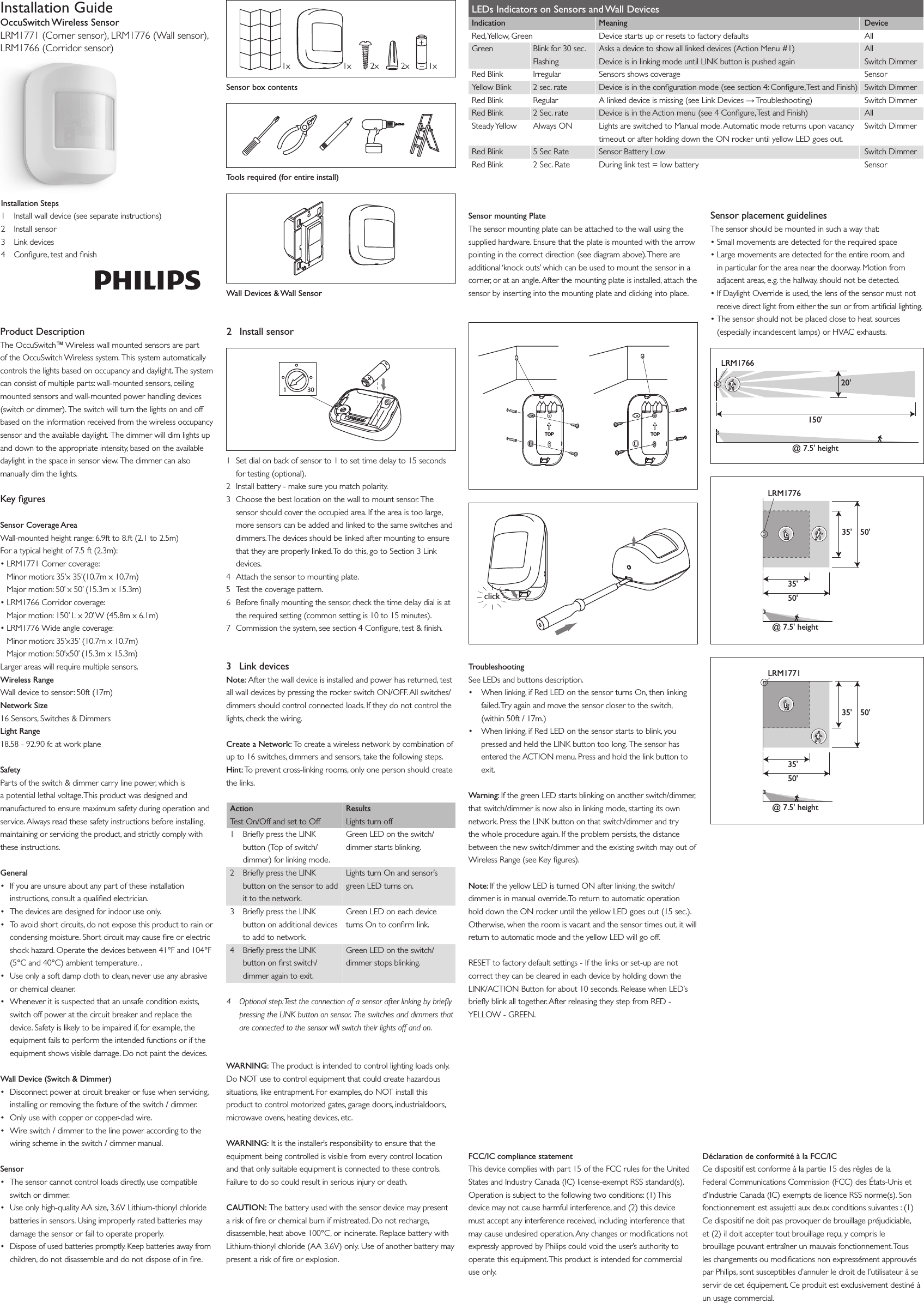
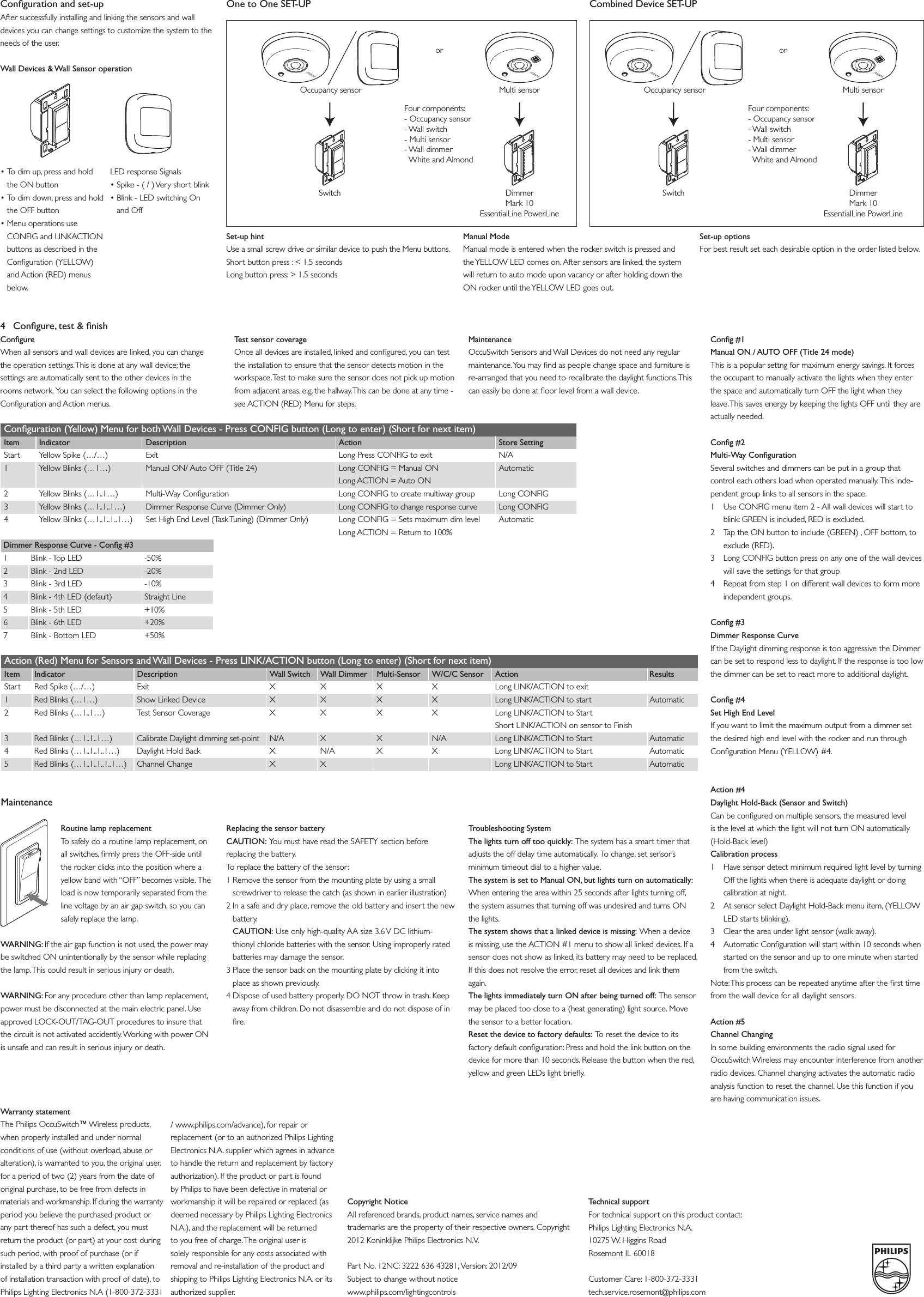
Philips Lighting North America LRM1766 Wireless 2.4GHz Light Switch Sensor User Manual 3222 636 43281 IG 20120910 LRM17xx A3V2Fin indd
Philips Lighting North America Corporation Wireless 2.4GHz Light Switch Sensor 3222 636 43281 IG 20120910 LRM17xx A3V2Fin indd
User Manual