Persistent systems RF2100 S-Band Radio Module User Manual 2
Persistent systems LLC S-Band Radio Module Users Manual 2
UserManual.wiki
>
Persistent systems
>
RF2100 User Manual
>
Users Manual 2
Contents
1.
Users Manual 1
2.
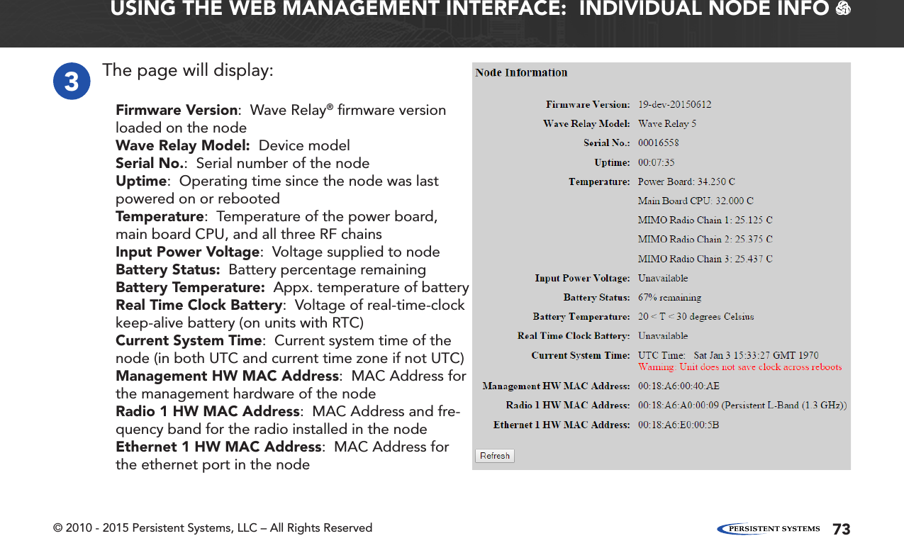
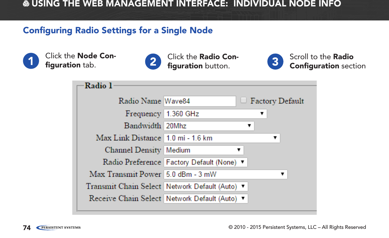
Users Manual 2
Users Manual 2
Navigation menu
Upload a User Manual
Namespaces
Wiki Guide
HTML
PDF
Info
Views
User Manual
Discussion / Help
Navigation