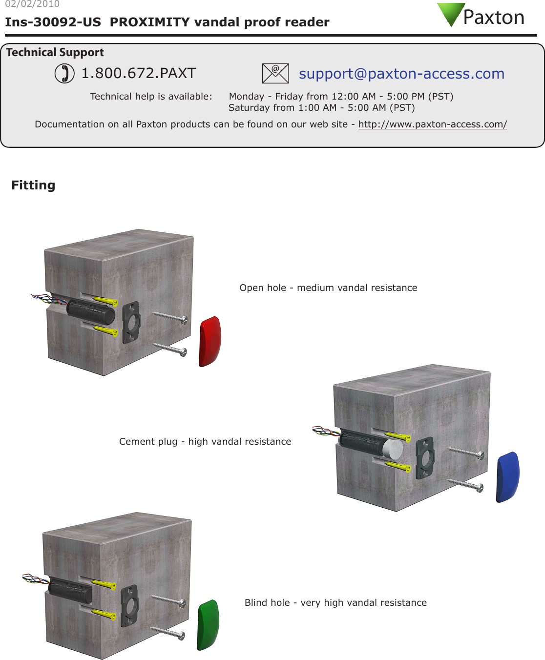
Paxton Access Z99UV30 Proximity Vandal Proof Reader User Manual INSTRUCTION PROXIMITY vandal proof reader

Paxton Access Ltd Proximity Vandal Proof Reader INSTRUCTION PROXIMITY vandal proof reader

User Manual

Ins-30092-US  PROXIMITY vandal proof reader02/02/2010Technical SupportTechnical help is available:     Monday - Friday from 12:00 AM - 5:00 PM (PST)                               Saturday from 1:00 AM - 5:00 AM (PST)1.800.672.PAXT support@paxton-access.comDocumentation on all Paxton products can be found on our web site - http://www.paxton-access.com/FittingOpen hole - medium vandal resistanceBlind hole - very high vandal resistanceCement plug - high vandal resistancePaxton
Cable extensionsReaders can be extended using Belden CR9540 10-core overall screened cable to a maximum of 100 yards.WiringThe reader port module is designed to convert the standard reader ports on Switch2 and Net2 controllers to accept one or two RJ45 connections.  Pull off the screw terminal block from the reader port and simply replace it with this module.This module can be used to provide a connection point for the reader RJ45 plug.  The terminals on the module are then wired color for color to the controller.Alternatively, the reader can be wired directly into the screw terminals of the control unit by rst cutting off the RJ45 plug and stripping back the wires in the cable.Reader Port Module  (325-030-US)This module may be purchased separately to speed up the installing and replacement of readers.Connection modulesFurther information on how to purchase Installer Tools is available at:  http://paxton.info/841Reader junction box  (325-020-US)Connection to a control unit reader port
1 - Readers/Keypads not working.Q- Software settings - Conrm that the settings of the reader or keypad are correct. Q- Connections - Check the wiring and integrity of the connectors.  If possible, test this reader on the other port.Q- Cable - Belden 9540 should be used to extend the reader cable (100yds maximum). Twisted pair alarm cableQ   should not be used. To conrm that an extended reader cable is not at fault, wire the reader directly to the port.Q- Supply voltage - Conrm that the voltage is within specication. (see table)Q- User token - Conrm that the user token used for testing is OK by presenting it to a known working reader.Q- Interference - Conrm whether the reader works when tested ‘in hand’ and not mounted on the wall. Q  Ensure PROXIMITY readers are not mounted back to back or that there is no interference from other RF devices. 2 - Readers / Keypads - Extending cable.QOnly Belden CR9538 / 9540 can be used for cable extensions. CR9538  8 core for up to 25yds, CR9540 10 core forQ25-100yds (maximum extension). With CR9540, the two additional cores should be used to double up the power.3 - Net2.  What to do if a user has no access - Check the reader LEDs when a card is shown. Q- No LEDs - the reader has no power. Q- No change in display - try the card on a known working reader. If there is still no response, replace the card. Q- Green LED ashing when a card is presented;  check relay 1 LED to check for activity and also the lock wiring. Q- Red LED is ashing when a card is presented;  check the validity of the user at the PC. Q   Check user’s access level and ensure they should have access by clicking on Current Validity. Q   Check the ‘Valid Until’ date and conrm this has not expired. Q- Reinstate the ACU from the doors screen. Select the ACU’s you wish to reinstate and then click OK. 4 - Switch2 - Adding an additional card pack.QYou need to be in possession of the original enrolment card. Present the original enrolment card to the reader andQthe Amber LED will ash, Green & Red LEDs will be off, then present the Enrolment card from the new card pack;Qthe reader will beep and all LEDS will be lit. The additional cards will now be valid. Repeat this with each readerQand with any additional card packs. Any valid enrolment card can be used to add further packs. This is the sameQfor enrolling function card packs onto a system.5 - Switch2 - How to reset the controller.Q1.  Disconnect the power and remove the wires from the Green and Mauve terminalsQ2.  Insert a wire link between the Green and Mauve terminalsQ3.  Reconnect the power (the unit will bleep 4 times)Q4.  Disconnect the power and remove the link wire, reconnect the Green and Mauve wiresQ5.  Reconnect the power (the unit will bleep 3 times per second). The unit is ready to be enrolled.Here is the list of topics about this product that receive the most technical support inquiries. We list them here to help you speed up the installation and trouble shooting process.Technical HelpReaders mounted together between readers12 inchesMounted on metal surfaceSuitabilitySecurity sensitive doorsWet environments
-20 °C (-4 °F)  +55 °C (+131 °F) IPX75 yards8V DC 14V DC  100 mA125 kHz600 µs3/4 inch 2 3/8 inch3 inch 1 1/2 inchVoltageClock and data bit period Carrier frequencySpecicationsOperating temperatures - all itemsElectricalEnvironment DimensionsMin MaxCurrentCable lengthRead Range Token Keyfob Hands Free TokenWaterproofMin MaxThis product is not suitable for retail sale.  All warranties are invalid if this product is not installed by a competent person.Outdoor Use Diameter DepthNot CompatibleFCC ComplianceThis device complies with Part 15 of the FCC Rules. Operation is subject to the following two conditions: (1) this device may not cause harmful interference, and (2) this device must accept any interference received, including interference that may cause undesired operation. Changes or modications not expressly approved by the party responsible for compliancecould void the user’s authority to operate the equipment.

Navigation menu