Paxton Access 380127 Proximity LCD Reader User Manual INSTRUCTION PROXIMITY LCD reader
Paxton Access Ltd Proximity LCD Reader INSTRUCTION PROXIMITY LCD reader
UserManual.wiki
>
Paxton Access
>
380127 User Manual
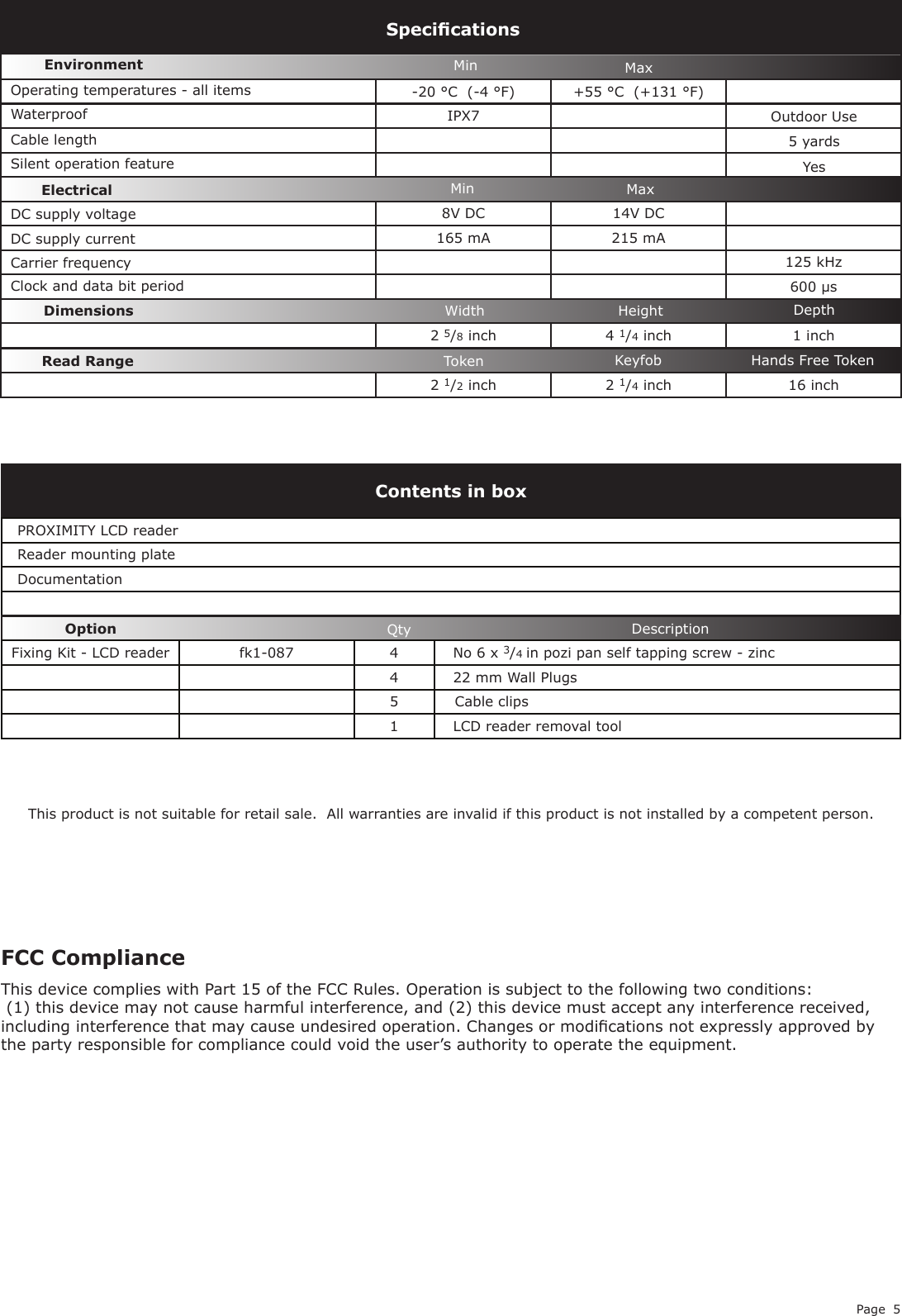
User Manual
Navigation menu
Upload a User Manual
Namespaces
Wiki Guide
HTML
PDF
Info
Views
User Manual
Discussion / Help
Navigation