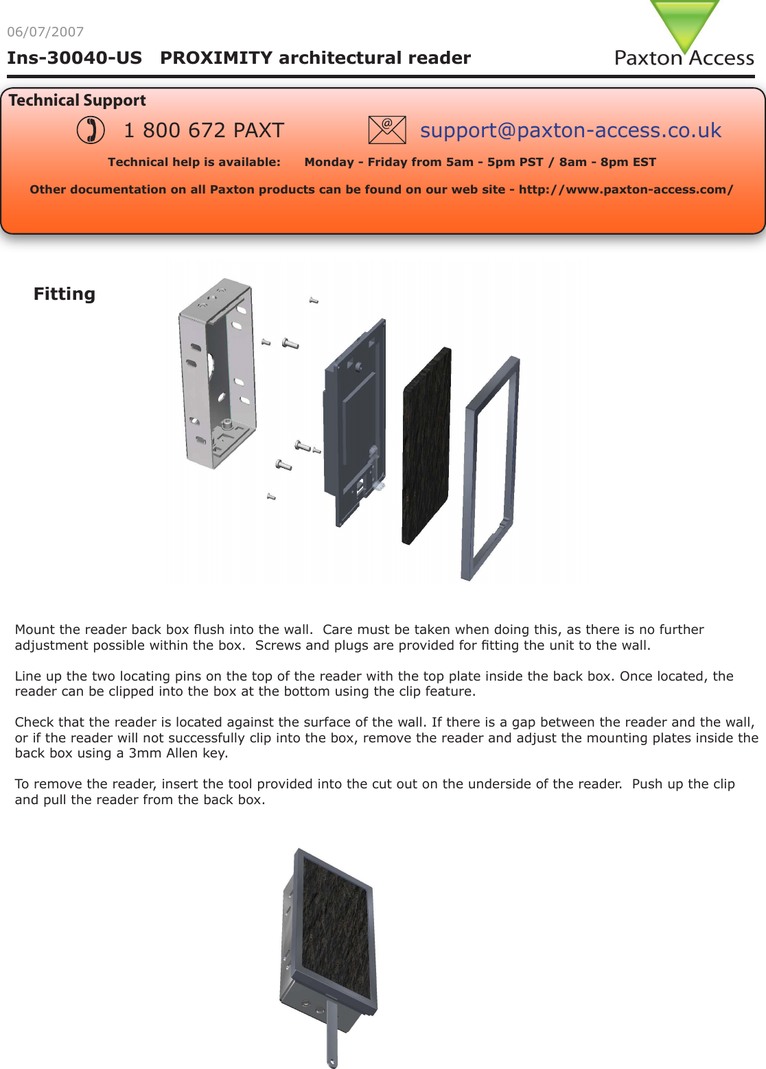
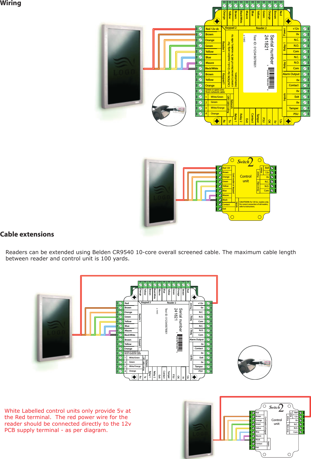
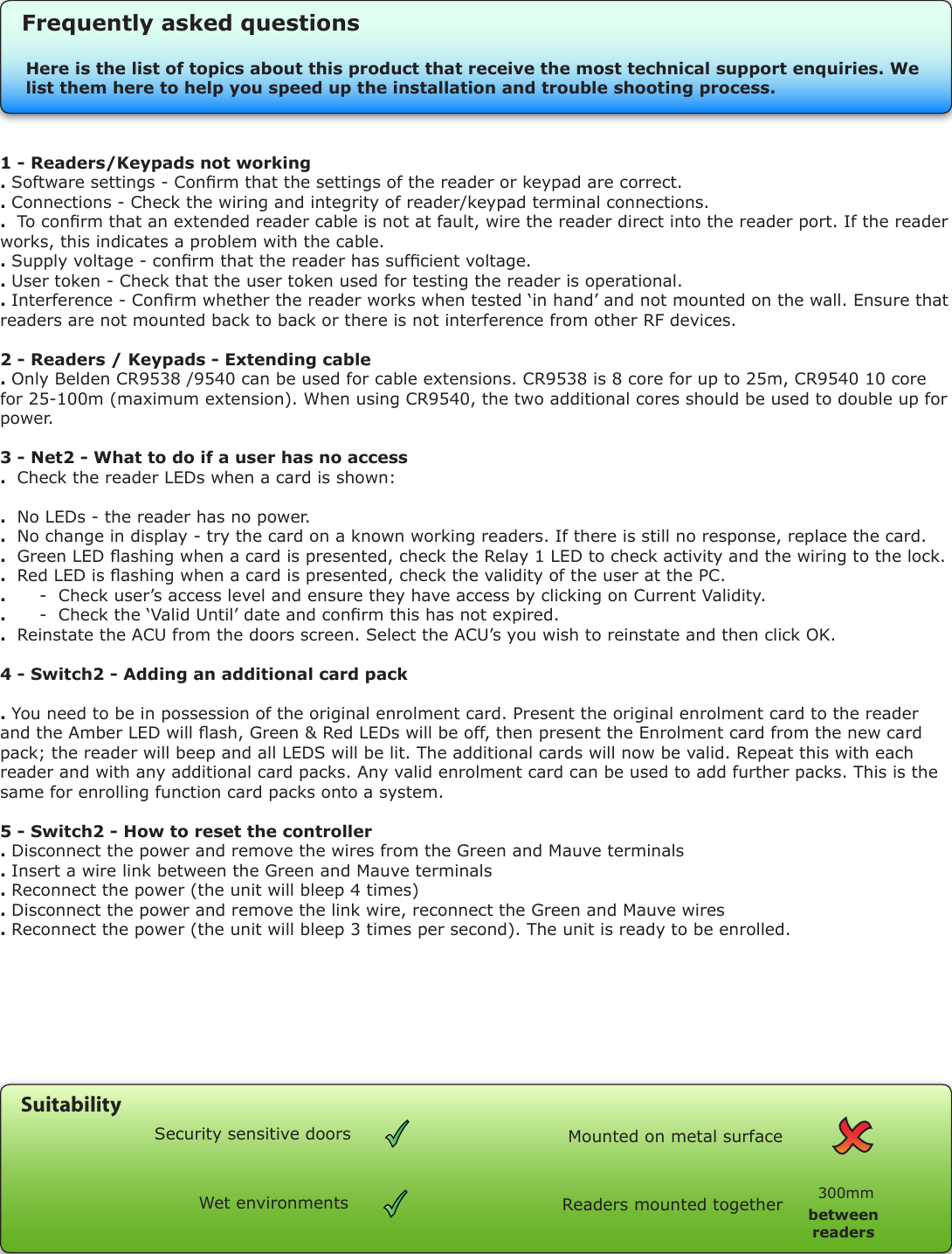
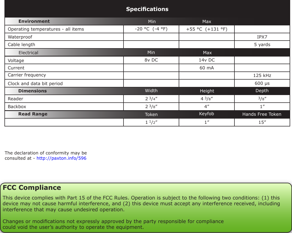
Paxton Access 360864 125 kHz Proximity Reader User Manual INSTRUCTION PROXIMITY architectural reader

Paxton Access Ltd 125 kHz Proximity Reader INSTRUCTION PROXIMITY architectural reader

User manual

Ins-30040-US   PROXIMITY architectural reader06/07/2007Technical SupportTechnical help is available:      Monday - Friday from 5am - 5pm PST / 8am - 8pm EST   Other documentation on all Paxton products can be found on our web site - http://www.paxton-access.com/1 800 672 PAXT support@paxton-access.co.ukFittingMount the reader back box ush into the wall.  Care must be taken when doing this, as there is no further adjustment possible within the box.  Screws and plugs are provided for tting the unit to the wall.Line up the two locating pins on the top of the reader with the top plate inside the back box. Once located, the reader can be clipped into the box at the bottom using the clip feature.Check that the reader is located against the surface of the wall. If there is a gap between the reader and the wall, or if the reader will not successfully clip into the box, remove the reader and adjust the mounting plates inside the back box using a 3mm Allen key.To remove the reader, insert the tool provided into the cut out on the underside of the reader.  Push up the clip and pull the reader from the back box.
RedBrownOrangeGreenYellowBlueMauveBlack/WhiteBrownYellowReader 1OrangeKeypad 1+12v0vN.C.N.O.ComN.C.N.O.ComAlarm Output0vContact0vExit0vTamperPSURxTxRelay 1Relay 2ExitContactTamperPSUOK5v12vRedBrownOrangeGreenYellowBlueMauveBlack/WhiteBrownYellowOrangeReader 2Keypad 2PowerRelay 1Relay 2InputsNetworkCAT5 cable codingWhite/GreenGreenWhite/OrangeOrange1234Screen or spare coresfrom network cableSerial number 241821Test ID: 012345678901z-144032 4 8 9 8 0 0 0 0 04RedBrownOrangeGreenYellowBlueMauveExitContactBlackCard reader or keypad 12v 0vN.C.N.O.ComBellPowerDoor relayAlarmwitch2SControlunitInputsWhite Labelled control units only provide 5v at the Red terminal.  The red power wire for the reader should be connected directly to the 12v PCB supply terminal - as per diagram.Cable extensionsRed 12v dcBrownOrangeGreenYellowBlueMauveBlack/WhiteBrownYellowReader 1OrangeKeypad 1+12v0vN.C.N.O.ComN.C.N.O.ComAlarm Output0vContact0vExit0vTamperPSURxTxRelay 1Relay 2ExitContactTamperPSUOK5v12vRedBrownOrangeGreenYellowBlueMauveBlack/WhiteBrownYellowOrangeReader 2Keypad 2PowerRelay 1Relay 2InputsNetworkCAT5 cable codingWhite/GreenGreenWhite/OrangeOrange1234Screen or spare coresfrom network cableCAUTION: for 12v d.c. readers only. Forcorrect connection of old 5v readers, refer to instructions.Serial number 241821Test ID: 012345678901z-144032 4 8 9 8 0 0 0 0 0 4Red 12VBrownOrangeGreenYellowBlueMauveExitContactBlackCard reader or keypad 12v 0vN.C.N.O.ComBellPowerDoor relayAlarmwitch2SControlunitInputsCAUTION: For 12V d.c. readers only. For correct connection of old readers, refer to instructions.Readers can be extended using Belden CR9540 10-core overall screened cable. The maximum cable length between reader and control unit is 100 yards.Wiring
1 - Readers/Keypads not working . Software settings - Conrm that the settings of the reader or keypad are correct. . Connections - Check the wiring and integrity of reader/keypad terminal connections. .  To conrm that an extended reader cable is not at fault, wire the reader direct into the reader port. If the reader works, this indicates a problem with the cable.. Supply voltage - conrm that the reader has sufcient voltage. . User token - Check that the user token used for testing the reader is operational.. Interference - Conrm whether the reader works when tested ‘in hand’ and not mounted on the wall. Ensure that readers are not mounted back to back or there is not interference from other RF devices. 2 - Readers / Keypads - Extending cable . Only Belden CR9538 /9540 can be used for cable extensions. CR9538 is 8 core for up to 25m, CR9540 10 core for 25-100m (maximum extension). When using CR9540, the two additional cores should be used to double up for power.3 - Net2 - What to do if a user has no access.  Check the reader LEDs when a card is shown:.  No LEDs - the reader has no power. .  No change in display - try the card on a known working readers. If there is still no response, replace the card. .  Green LED ashing when a card is presented, check the Relay 1 LED to check activity and the wiring to the lock. .  Red LED is ashing when a card is presented, check the validity of the user at the PC. .      -  Check user’s access level and ensure they have access by clicking on Current Validity. .      -  Check the ‘Valid Until’ date and conrm this has not expired. .  Reinstate the ACU from the doors screen. Select the ACU’s you wish to reinstate and then click OK.4 - Switch2 - Adding an additional card pack. You need to be in possession of the original enrolment card. Present the original enrolment card to the reader and the Amber LED will ash, Green & Red LEDs will be off, then present the Enrolment card from the new card pack; the reader will beep and all LEDS will be lit. The additional cards will now be valid. Repeat this with each reader and with any additional card packs. Any valid enrolment card can be used to add further packs. This is the same for enrolling function card packs onto a system.5 - Switch2 - How to reset the controller. Disconnect the power and remove the wires from the Green and Mauve terminals. Insert a wire link between the Green and Mauve terminals. Reconnect the power (the unit will bleep 4 times). Disconnect the power and remove the link wire, reconnect the Green and Mauve wires. Reconnect the power (the unit will bleep 3 times per second). The unit is ready to be enrolled.Here is the list of topics about this product that receive the most technical support enquiries. We list them here to help you speed up the installation and trouble shooting process.Frequently asked questionsReaders mounted together between readers300mmMounted on metal surfaceSuitabilitySecurity sensitive doorsWet environments
The declaration of conformity may be consulted at - http://paxton.info/596VoltageClock and data bit period Carrier frequency-20 °C  (-4 °F) +55 °C  (+131 °F)IPX75 yards8v DC 14v DC  60 mA125 kHz600 µs2 3/4”4 3/8”3/8”2 3/8”4” 1”1 1/2” 1” 15”SpecicationsOperating temperatures - all itemsElectricalEnvironment DimensionsMin MaxDepthWidthCurrentCable lengthRead Range Token Keyfob Hands Free TokenWaterproofMin MaxHeightReaderBackboxFCC ComplianceThis device complies with Part 15 of the FCC Rules. Operation is subject to the following two conditions: (1) this device may not cause harmful interference, and (2) this device must accept any interference received, including interference that may cause undesired operation. Changes or modications not expressly approved by the party responsible for compliancecould void the user’s authority to operate the equipment.

Navigation menu