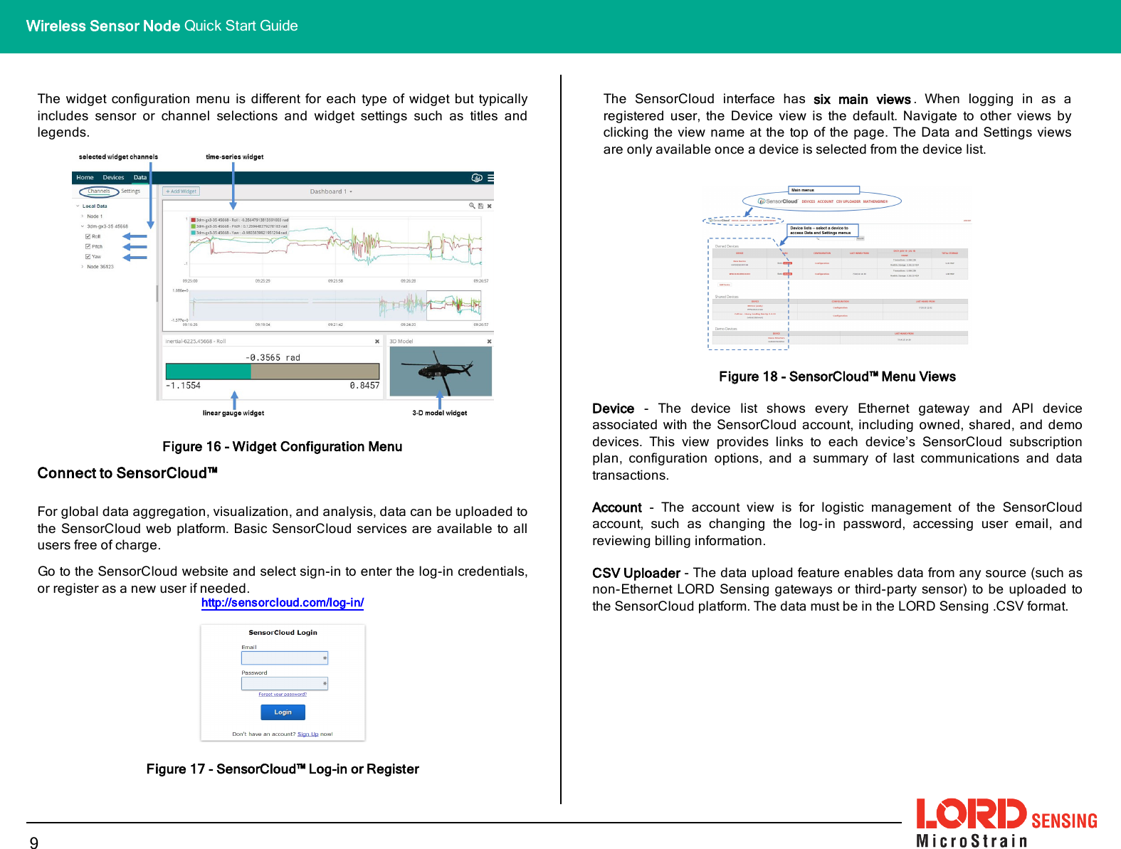
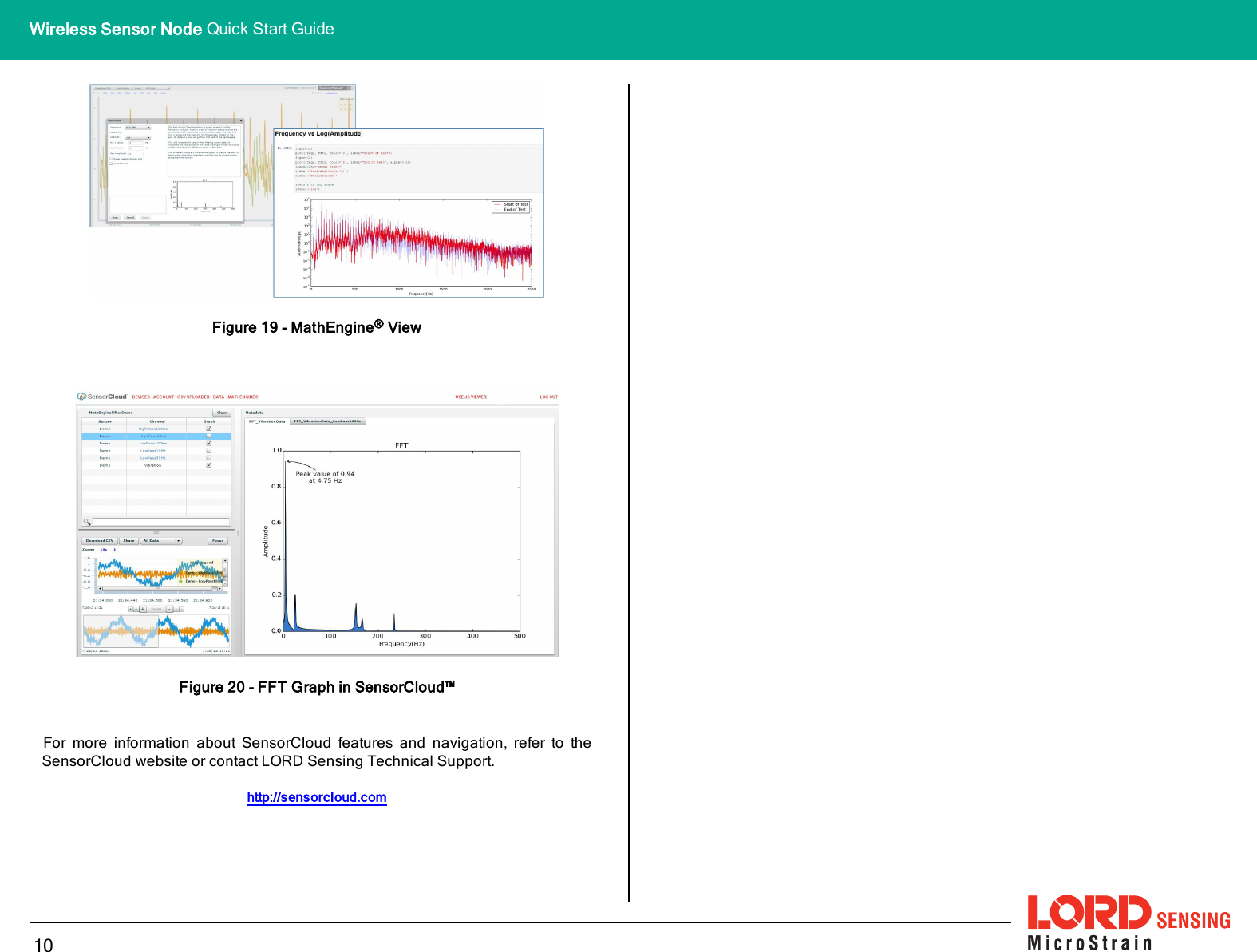
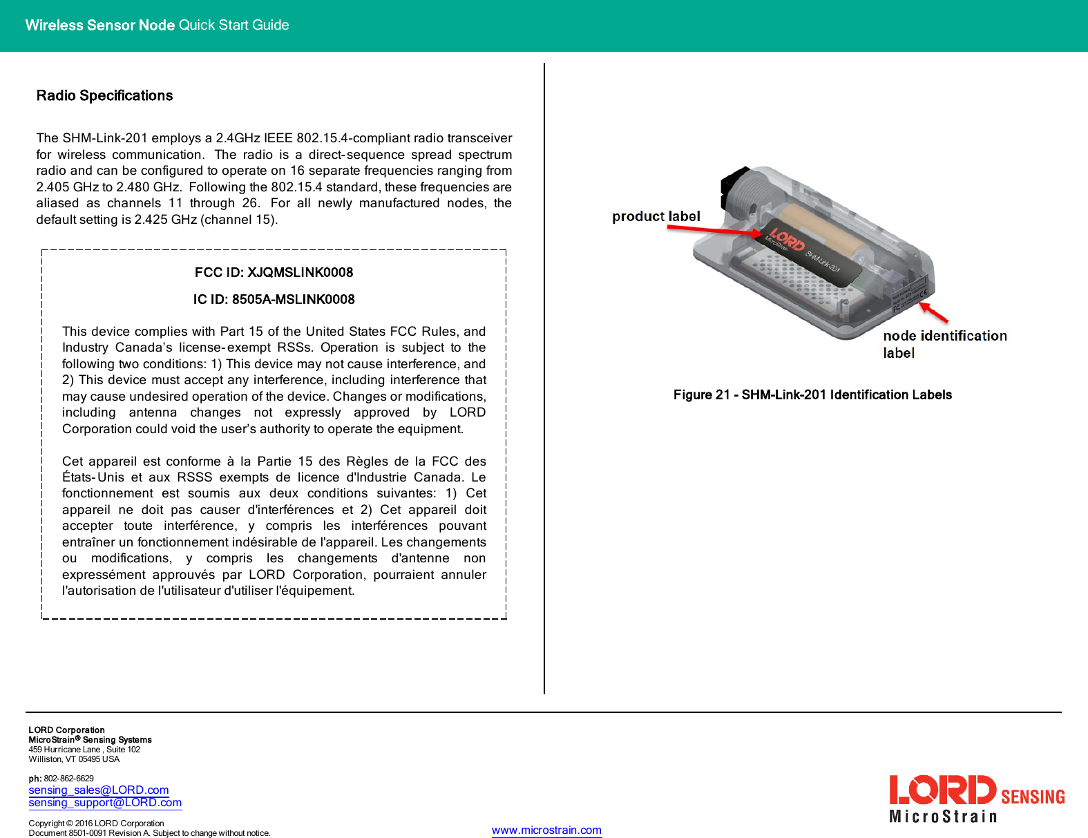
Parker Hannifin MSLINK0008 Wireless Sensor Node User Manual My

Lord Corporation Wireless Sensor Node My

Exhibit D Users Manual per 2 1033 b3

LORD QUICK START GUIDESHM-Link-201Ruggedized Wireless Structural Health Monitoring NodeNODEOVERVIEWThe SHM- Link- 201 structural health monitoring node is used for in- situ,multidimensional measurement and analysis of component strain and fatigue.The SHM-Link-201 has three input channels and is designed to integrate withfield-installed strain gauge rosettes.The SHM-Link-201 embedded processing algorithms provide sophisticated dataoutputs, including damage estimations using user- configurable strain numbercurves, estimations along various user-configurable angles, and an ASTM e1049rainflow- counting histogram output. Sampling modes include continuous andactivity-sense. The SHM-Link-201 is designed for extended use with a lithiumbattery.To acquire sensor data, the SHM-Link-201 is used with any LORD Sensing datagateway, such as the WSDA®-Base -10x-LXRS®, or the network-ready WSDA®-1500 - LXRS ®. The SensorConnect software interface is used for nodeconfiguration, and SensorCloud™ is available for advanced data visualization,aggregation, and analysis. Users can also build custom software interfaces withthe MicroStrain Communications Library (MSCL).Figure 1 - Wireless Sensor NodeFigure 2 - Node ComponentsItem Description QuantityASHM-Link-201node assembly 1BBattery compartment cap 1CBattery compartment o-ring 1DBattery tray 1EStrain gauge bonding cable 1FDielectric grease (not shown) 1Table 1 - Component ListWireless Simplicity, Hardwired Reliability™
The SHM- Link- 201 interfaces includes a battery compartment andaccommodations for strain gauges and node installation. A device statusindicator is visible through a light-pipe below the product label.Indicator Behavior Node StatusDevicestatusindicatorOFF Node is OFFRapid multi-color flash onstart-up Node is booting upSlow pulse ~ once/2 sec Node is idle and waiting for acommandQuick blink ~ once/sec Node is samplingQuick blink ~ once/10 sec Node is in sleep modeTable 1 - Indicator BehaviorsNODEDEPLOYMENTThe SHM-Link-201 is designed for use with the provided bonding cable. Thecable connects the node and strain gauges in a way that allows the gauges to fitunderneath the node in the strain gauge cavity, protected from damage. Thestrain gauge cavity can also be sealed after installation. The following procedureoutlines this process. These steps may not be necessary for all applications butprovide the best protection for the node circuitry and the gauges.Install the Node BatteryThe SHM-Link-201 operates on an internalAA-type battery with a voltage between 1 Vdc and 5 V dc. Use only batteries that meetthis specification. Do not short circuit, crush,puncture, or otherwise misuse the battery.Disposal is subject to federal and local laws.2Wireless Sensor Node Quick Start Guide
1. Remove the SHM-Link-201 battery compartment cap.2. Position a pliers or a hook-ended tool behind the battery tray screw-head.Pull firmly outward, or leverage the edge of the housing, to release thetray from the terminals inside. It should unseat and slide out.Figure 3 - Battery Compartment Assembly3. Apply dielectric grease to the battery tray terminals.4. Install the battery.5. Firmly re-seat the battery tray in the battery compartment6. Install the compartment cap, ensuring the o-ring remains intact and prop-erly seated.Test Fit Node and Gauge Assembly7. Determine the location of the component to be monitored where the straingauges will be installed.8. Place the bonding cable and node in the chosen location to verify gaugeplacement and that there is space for the node to fit over the top of them.The gauges are installed in the cable cutout, and the node strain gaugecavity fits over the gauges and cable.Figure 4 - Gauge and Node LocationInstall Strain GaugesNOTEFor accurate fatigue data, strain gauge installation must be completed incompliance with strain gauge manufacturer recommendations andindustry standard processes such asASTM E1237-93, Standard Guidefor Installing Bonded Resistance Strain Gauges. Failure to properlyattach and connect the gauges will result in erroneous data.3Wireless Sensor Node Quick Start Guide
9. Wire the strain gauges to the bonding cable so that the strain gaugeassembly will be positioned in the central cutout .10. Bond the cable and strain gauges onto the surface of the component to bemonitored with strain gauge adhesive or equivalent. Install the gauges inthe desired orientation for measurement and in accordance with the straingauge manufacturers installation instructions.Figure 5 - Strain Gauge WiringConnect Node to Strain Gauges and Test11. Connect the node to the strain gauge assembly. Attach the bonding cableto one of the node connectors in the orientation shown. Two are providedfor node positioning convenience and have identical pins. The cableshould lay flat against the bottom of the node circuit board and wrap upthe edge of it to plug into the connecter.12. Place the node over the strain gauge assembly and verify the straingauge cavity covers the strain gauge assembly without damaging it.13. Test the strain gauage installation and basic node functioning by per-forming an auto-calibration in SensorConnect (See Calibrate the Node onpage 7).Figure 6 - Connecting to the NodeInstall and Seal the Node14. Remove the node battery or put it in sleep mode (to conserve battery life).Verify the node power switch is in the ON position. Once the node issealed, the access door will no longer open.15. Close the node interface access door and remove the installation tapebacking from the bottom of the node. Adhere the node in place over thegauges.16. Apply a high-strength adhesive sealant (such as Sikaflex®255 FC or equi-valent) around the perimeter of the node where it meets the componentsurface.17. Remove the set screws from the sealant injection hole, and fill the straingauge cavity with a flexible, injectable sealant (such as Self-LevlingGreen, or equivalent). Avoid over-filling the sealant and allowing it to leakinto other cavities (such as the battery compartment and under the accessdoor). This is more likely to happen if the node is mounted vertically.4Wireless Sensor Node Quick Start Guide
Make System ConnectionsTo acquire sensor data, the SHM-Link-201 is used with a LORD Sensing datagateway such as the WSDA®-200-USB or WSDA®-1500 - LXRS®. Connect thegateway to the computer or network and to a power source as required. Refer tothe gateway user manual for more information.Figure 7 - System ConnectionsNode Operational ModesFigure 8 - Node Operational Modes5Wireless Sensor Node Quick Start Guide
Synchronized SamplingUse the Base Station menu to start sampling for multiple nodes in SynchronizedSampling mode. For single nodes, or non- synchronized sampling, the nodemenu can be used.Figure 9 - Base Station MenuSoftware Installation and NavigationSensorConnect can be installed on any Windows operating system (Vista ornewer). The installer is downloaded from the LORD Sensing website and is alsoprovided with many products.There are three main pages: Home, Devices, and Data, which are alwaysaccessible at the top of page. A quick-link to the SensorCloud™ platform log-inand a software settings menu is also available here. On start-up the softwarescans for attached sensors and then opens the home page.Figure 10 - SensorConnect Home PageSensorConnect automatically detects any LORD Sensing device plugged into anactive port. Device connections are managed on the Devices page. The menuoptions will vary between devices (such as gateways, nodes, and sensors) buthave similar interfaces.Figure 11 - Devices Page6Wireless Sensor Node Quick Start Guide
Devices list - Found devices appear in the device list. This list also includespreviously found devices even when the software is restarted.Selected device and device menu - Each type of device has its own menu. Onceselected, the device name is highlighted, and the corresponding menu displayed.Menu options vary between devices but typically include device configuration,start sampling, sensor mode selections, and data downloading. Click on thedevice name (in the devices list) to get back to the main device menu.Add Device - Manually add a device if it does not appear automatically. .Notifications and indicators - information specific to a device, or in response to arequested action, appears next to the applicable device name in the device list, orin the device menu. These notifications provide information about deviceperformance, such as communication and sampling status. Green typicallyindicates confirmed actions, while orange indicates information that may requirefurther action. Blue indicates they are currently sampling.Configure the NodePower settings, some sampling settings, data output options, and gauge settingsspecific to the SHM-Link-201 are adjustable through the Configure menu. Allother settings are adjusted when sampling is started. Click Apply to savechanged settings.Figure 12 - Configure MenuHardware - Set the strain gauge provided by the gauge manufacturer.Fatigue - Select from data output options that produce fatigue measurements.Histogram - Set the rainflow-counting bin thresholds and data transmit rate. Datawill still be collected at the rate set in the Start Sampling menu.Activity Sense - Activity sense mode is power- saving mode. When enabled,sampling will only occur when movement is detected by the internalaccelerometer. Sampling will occur at the rate set in the Start Sampling menuuntil the (also configurable) inactivity period has passed.Power - Set the node transmit power, radio-check interval (when the node goesinto sleep mode), and the inactivity timeout.Calibrate the NodeCalibration of the SHM-Link-201 is done through an internal circuit. With thestrain gauges connected, simply open the Auto-Calibrate menu, and select theCalibrate button. This will calibrate all three channels automatically. If the gaugesare connected correctly, and the calibration is completed, "Success" will beindicated in the status column. Otherwise it will indicate the sensor is detached.Figure 13 - Calibration Menu7Wireless Sensor Node Quick Start Guide
IMPORTANT:Auto- calibration must beperformed anytime sampling settingsare changed.Start SamplingData sampling is initiated for each device through its device menu. For a wirelesssensor network, sampling can also be started for the entire network by initiatingsampling from the network gateway menu. The sampling menu options varydepending on the type of device.Figure 14 - Sampling MenuSampling menu - The sampling menu typically includes options for samplingmode, sample rate, and sample duration. Apply the settings to begin collectingdata.Sampling indicator - The sampling indicator shows when data is being collectedfrom the device. At slow sampling rates it will turn on and off as readings aretaken, while at fast sampling rates it will be on continuously.Create Data ViewsCollected data is viewed on the Data page through the creation of dashboardsand widgets. Think of dashboards as individual pages and widgets as anillustration on the page. Create multiple data widgets on each dashboard todisplay sampled data as a time-series graph, text chart, or a simple gauge thatonly displays the most current reading.This format provides an easy way to organize many sensors and networks, and itallows the information to be displayed in the most appropriate layout.Figure 15 - Data PageUse the mouse along with the shift and control keys inside the graph window toadjust the data view.Control ActionMouse wheel Zoom in/out onx-axisShift + mouse wheel Zoom in/out ony-axisMouse double-click Zoom to extendsShift + mouse left-click and drag left/right Zoom window left/rightShift + mouse left-click and drag up/down Zoom window up/downCtrl +mouse left-click and drag Zoom boxTable 2 - Graph View Controls8Wireless Sensor Node Quick Start Guide
The widget configuration menu is different for each type of widget but typicallyincludes sensor or channel selections and widget settings such as titles andlegends.Figure 16 - Widget Configuration MenuConnect to SensorCloud™For global data aggregation, visualization, and analysis, data can be uploaded tothe SensorCloud web platform. Basic SensorCloud services are available to allusers free of charge.Go to the SensorCloud website and select sign-in to enter the log-in credentials,or register as a new user if needed.http://sensorcloud.com/log-in/Figure 17 - SensorCloud™ Log-in or RegisterThe SensorCloud interface has six main views . When logging in as aregistered user, the Device view is the default. Navigate to other views byclicking the view name at the top of the page. The Data and Settings viewsare only available once a device is selected from the device list.Figure 18 - SensorCloud™ Menu ViewsDevice - The device list shows every Ethernet gateway and API deviceassociated with the SensorCloud account, including owned, shared, and demodevices. This view provides links to each device’s SensorCloud subscriptionplan, configuration options, and a summary of last communications and datatransactions.Account - The account view is for logistic management of the SensorCloudaccount, such as changing the log- in password, accessing user email, andreviewing billing information.CSVUploader - The data upload feature enables data from any source (such asnon-Ethernet LORD Sensing gateways or third-party sensor) to be uploaded tothe SensorCloud platform. The data must be in the LORD Sensing .CSV format.9Wireless Sensor Node Quick Start Guide
Figure 19 - MathEngine®ViewFigure 20 - FFT Graph in SensorCloud™For more information about SensorCloud features and navigation, refer to theSensorCloud website or contact LORD Sensing Technical Support.http://sensorcloud.com10Wireless Sensor Node Quick Start Guide
Wireless Sensor Node Quick Start GuideRadio SpecificationsThe SHM-Link-201 employs a 2.4GHz IEEE 802.15.4-compliant radio transceiverfor wireless communication. The radio is a direct-sequence spread spectrumradio and can be configured to operate on 16 separate frequencies ranging from2.405 GHz to 2.480 GHz. Following the 802.15.4 standard, these frequencies arealiased as channels 11 through 26. For all newly manufactured nodes, thedefault setting is 2.425 GHz (channel 15).FCC ID: XJQMSLINK0008IC ID: 8505A-MSLINK0008This device complies with Part 15 of the United States FCC Rules, andIndustry Canada’s license- exempt RSSs. Operation is subject to thefollowing two conditions: 1) This device may not cause interference, and2) This device must accept any interference, including interference thatmay cause undesired operation of the device. Changes or modifications,including antenna changes not expressly approved by LORDCorporation could void the user’s authority to operate the equipment.Cet appareil est conforme à la Partie 15 des Règles de la FCC desÉtats-Unis et aux RSSS exempts de licence d'Industrie Canada. Lefonctionnement est soumis aux deux conditions suivantes: 1) Cetappareil ne doit pas causer d'interférences et 2) Cet appareil doitaccepter toute interférence, y compris les interférences pouvantentraîner un fonctionnement indésirable de l'appareil. Les changementsou modifications, y compris les changements d'antenne nonexpressément approuvés par LORD Corporation, pourraient annulerl'autorisation de l'utilisateur d'utiliser l'équipement.Figure 21 - SHM-Link-201 Identification LabelsLORDCorporationMicroStrain®Sensing Systems459 Hurricane Lane , Suite 102Williston, VT 05495 USAph: 802-862-6629sensing_sales@LORD.comsensing_support@LORD.comCopyright © 2016 LORD CorporationDocument 8501-0091 Revision A. Subject to change without notice. www.microstrain.com

Navigation menu