Parker Hannifin MSLINK0003 2.4 GHz Radio Module User Manual x
MicroStrain, Inc. 2.4 GHz Radio Module x
UserManual.wiki
>
Parker Hannifin
>
MSLINK0003 User Manual
manual
Navigation menu
Upload a User Manual
Namespaces
Wiki Guide
HTML
PDF
Info
Views
User Manual
Discussion / Help
Navigation
![SerialLink Manual Serial-Link Serial Packet Protocol (SPP) Draft version 1.20, for Internal MicroStrain use only Working Draft: 8/7/2012 Overview The Serial-Link Serial Packet Protocol (SPP) defines a standard for delivery of data and commands over the Serial-Link UART communications pipeline. To communicate, each device is capable of reading, responding to, and forwarding an SPP Packet. Any device may originate a message and receive a reply from any other device. A single packet may be delivered to multiple devices. If a device does not exist on the pipeline, or is incapable of responding to a particular packet, it replies with an error, but will propagate the packet to the next device, if it exists, so that the next device may respond to the packet. The protocol to send a packet is shown below. Hardware UART specifications 115,200 bps, no parity, 8 data bits, 1 stop bit Packet Description The basic structure of the SPP Packet looks like this: Start Of Packet (SOP): 0xAA Delivery Stop Flags: <1 byte> App Data Type: <1 byte> Node Address: <2 bytes> Application data Length: <1 byte> Application data: <0 to 100 bytes> CheckSum: <2 bytes> The size of the packet is always AppDataLength + 8 (except for a variant – see Packet Variants) and the checksum is always the last 2 bytes (even for variants). Start Of Packet (SOP) (1 byte: Pkt[0]): The start of packet is a single byte of the value 0xAA (or binary 10101010) Delivery Flags (1 byte: Pkt[1]) Delivery flag instructs the receiving device how to act upon reception of the packet. This is currently fixed at a hex value 01H which instructs the receiving device to forward the received packet over its UART.](https://usermanual.wiki/Parker-Hannifin/MSLINK0003/User-Guide-1778873-Page-1.png)
![App Data Type (previously: Address Mode) (1 byte: Pkt[2]) The App Data Type defines the type of the application data. It allows the target MCU to determine what to do with the payload. If a target MCU does not recognize the App Data Type, it simply ignores it (or generates an error reply). Even if a target does not recognize the App Data Type, it should still pass the packet through to the next target (if any). All devices should utilize the Standard Command App Data Type (and the corresponding Command Packet Reply) for most I/O. Standard command app data has an App Data type value of 0. The Application Data in a standard command packet contains a 2 byte (16 bit, MSB:LSB) command followed by command data (if any). The standard command generally reflects available serial (non-packet) commands for a device. In other words, the application data of a standard command data type is simply a standard serial command wrapped in a packet header and checksum. If a Command Packet generates a reply, the reply should be in a Command Packet Reply App Data Type. Other standard App Data Types are: App Data Type Name Description 00 Command packet 2 byte command + command data 01 Cmd Packet reply 2 byte echoed cmd + cmd result 02 Error reply packet 2 bytes of error code Node Address (2 bytes: Pkt[3] Pkt[4]) In outbound packets the Node Address is the address of the wireless link node. The exception is the “broadcast” address which is defined as 0xFFFF (65535). Packets addressed to 0xFFFF are received and processed by all nodes. The node address allows the Serial-Link pipeline to become a “star” network at the base station to link board device. Each node on the star has an individual 16 bit address with valid address values being in the range of 1 to 65535. Practically speaking, a single star cannot have 65535 nodes at one time. The practical limit depends primarily on the duty cycle of the nodes, the limitations of the supporting host software, and the link quality or LQI (in the case of a wireless link). Application Data Length (1 byte: Pkt[5]) The maximum application data is restricted to 100 bytes. It may contain any binary data. Application Data (0 - 100 bytes: Pkt[6] -> Pkt[AppDataLen + 5]) In the SerialLink system, there are some commands carried in the application data that are common to all devices and so no prior knowledge of the type of device is needed, but there are many command and data application datas that are specific to a particular device. These commands are referenced in the documentation for the particular device.](https://usermanual.wiki/Parker-Hannifin/MSLINK0003/User-Guide-1778873-Page-2.png)
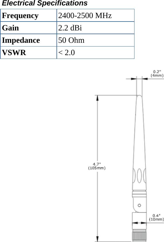
![As a general convention, multi-byte values in the application data are recommended to be represented as big-endian values (MSB:LSB). Several standard app data types Checksum (2 bytes: Pkt[AppDataLen + 6], Pkt[AppDataLen + 7]) The checksum is a 16 bit big-endian integer (MSB:LSB) that is the byte-wise sum of all the bytes in the packet starting AFTER the SOP and ending with the last byte of the application data. The SOP is not part of the checksum. In packet variants (see Packet Variants) additional packet bytes between the application data and the checksum bytes are NOT included in the checksum. The length of the array that is checksummed is AppDataLength + 5. The total size of the packet including the checksum bytes is AppDataLength + 8. POWERING THE DEVICE AND CONNECTING TO THE UART The device is powered by providing a DC voltage between 3.3 volts and 10 volts on pin 4 of the input connector. The ground return is provided on Pin 14 of the input connector. The voltage input is internally regulated to provide a steady 3.0 Voltage source to the board. Pin 19 is the Transmit Line of the UART, this should be connected to the receive line of the interface microprocessor. Pin 18 is the RX Line of the UART, this should be connected to the transmit line of the interface microprocessor. The interface voltage levels should be 3.0 V +/ 0.3 V. ALLOWABLE ANTENNAE The device has been tested for FCC approval with the following antenna. This antenna must be used with this module. The external antenna connects to the module via a u.FL connector. HG2402RD-RSF Manufacturer: L-Com](https://usermanual.wiki/Parker-Hannifin/MSLINK0003/User-Guide-1778873-Page-3.png)