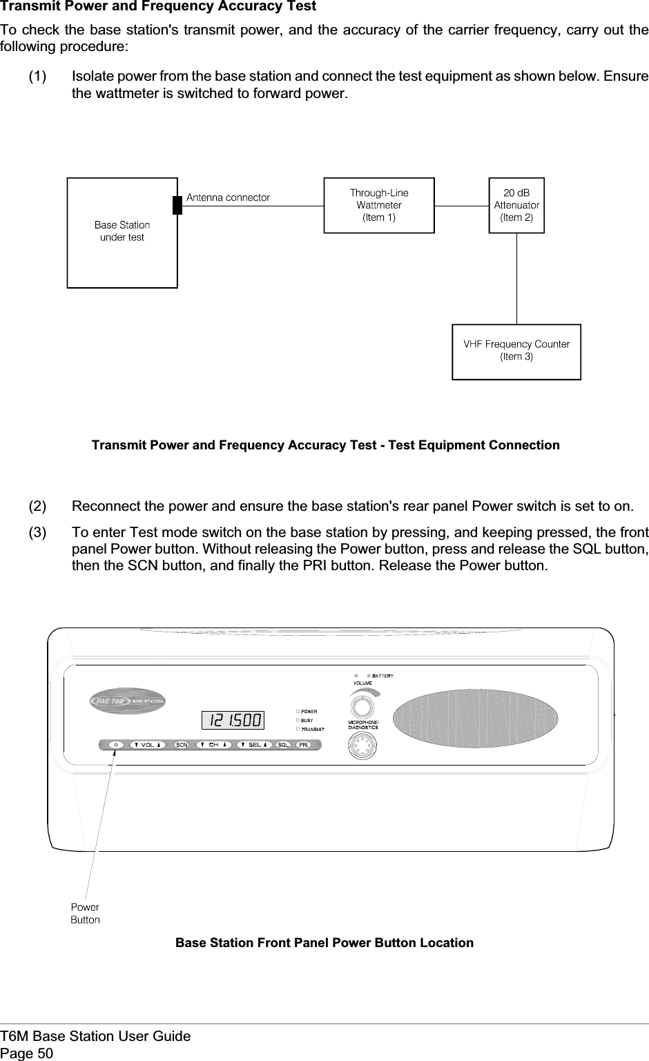
Park Air Systems BT6MBS User Manual User Guide
Park Air Systems Limited User Guide
UserManual.wiki
>
Park Air Systems
>
BT6MBS User Manual
User Guide
Navigation menu
Upload a User Manual
Namespaces
Wiki Guide
HTML
PDF
Info
Views
User Manual
Discussion / Help
Navigation
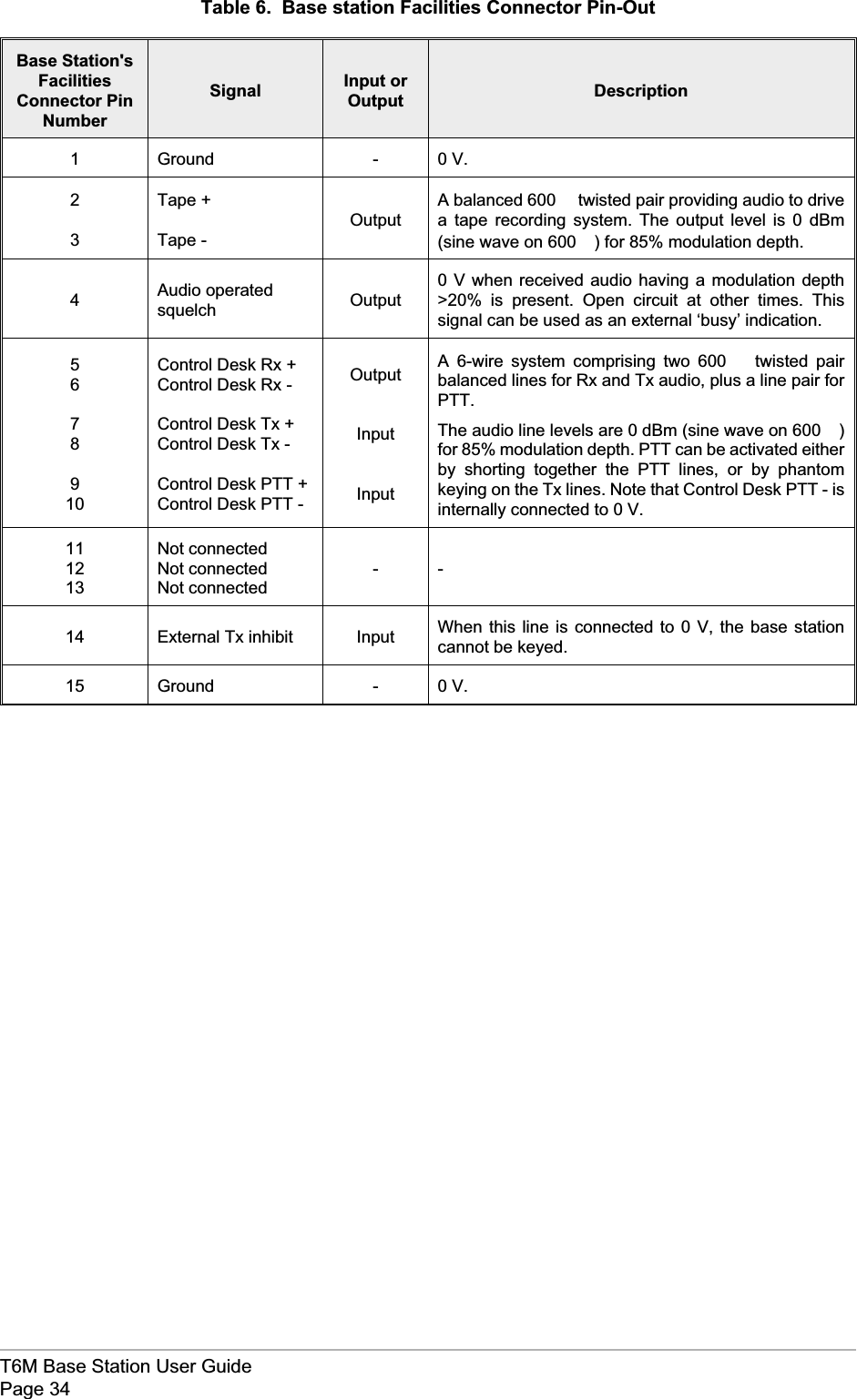
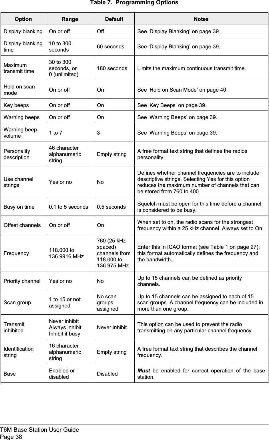
![SAFETYWarnings[Failure to comply with warnings can result in personal injury, fire, or electric shock.]qDO NOT operate equipment at high volume levels. Hearing experts advise against continuoushigh volume operation. If you experience ringing in your ears, reduce the volume level, ordiscontinue use.qThe Radio module's power amplifier circuit contains beryllium oxide that can be extremely toxic.No instructions within this user guide remove any of the radio module's covers so users are notexposed to a potential beryllium hazard. If the radio module is to be disposed of, users must beaware of current disposal regulations regarding equipment containing beryllium.qThe antenna used with this radio equipment must be installed such that the resultant radiatedfield strength is below 10 W/m²in areas normally accessible to personnel.qThe base station can be fitted with an optional internal battery. It is a sealed lead-acid type with athixotropic electrolyte. The battery has self sealing safety vents that may release small quantitiesof gas under extreme conditions. Because of this, users must ensure that the enclosure's ventsare always free from obstruction.FEDERAL COMMUNICATIONS COMMISSION (FCC) REGULATIONSqThis device complies with Part 15 of the FCC Rules. Operation is subject to the condition that thisdevice does not cause harmful interference.qYou are required to obtain a station licence before transmitting from your base station.qThis equipment is only licenced for operation on 25 kHz channel spacing. Operation on 8.33 kHzchannel spacing is not allowed within the USA.qThe base station power output must not exceed the output necessary for satisfactory technicaloperation taking account of local conditions and the area to be covered.qThe base station's frequency and parameters should be checked by authorized servicepersonnel before use, and at least yearly thereafter.T6M Base Station User GuidePage 4](https://usermanual.wiki/Park-Air-Systems/BT6MBS/User-Guide-120544-Page-4.png)


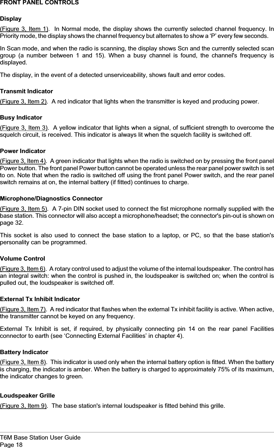
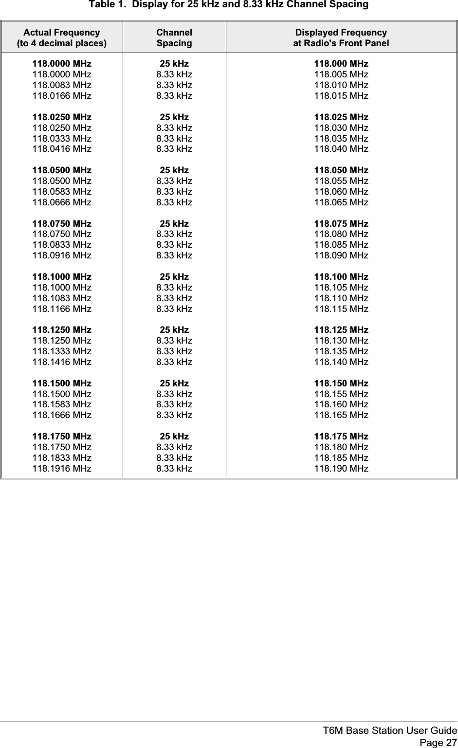
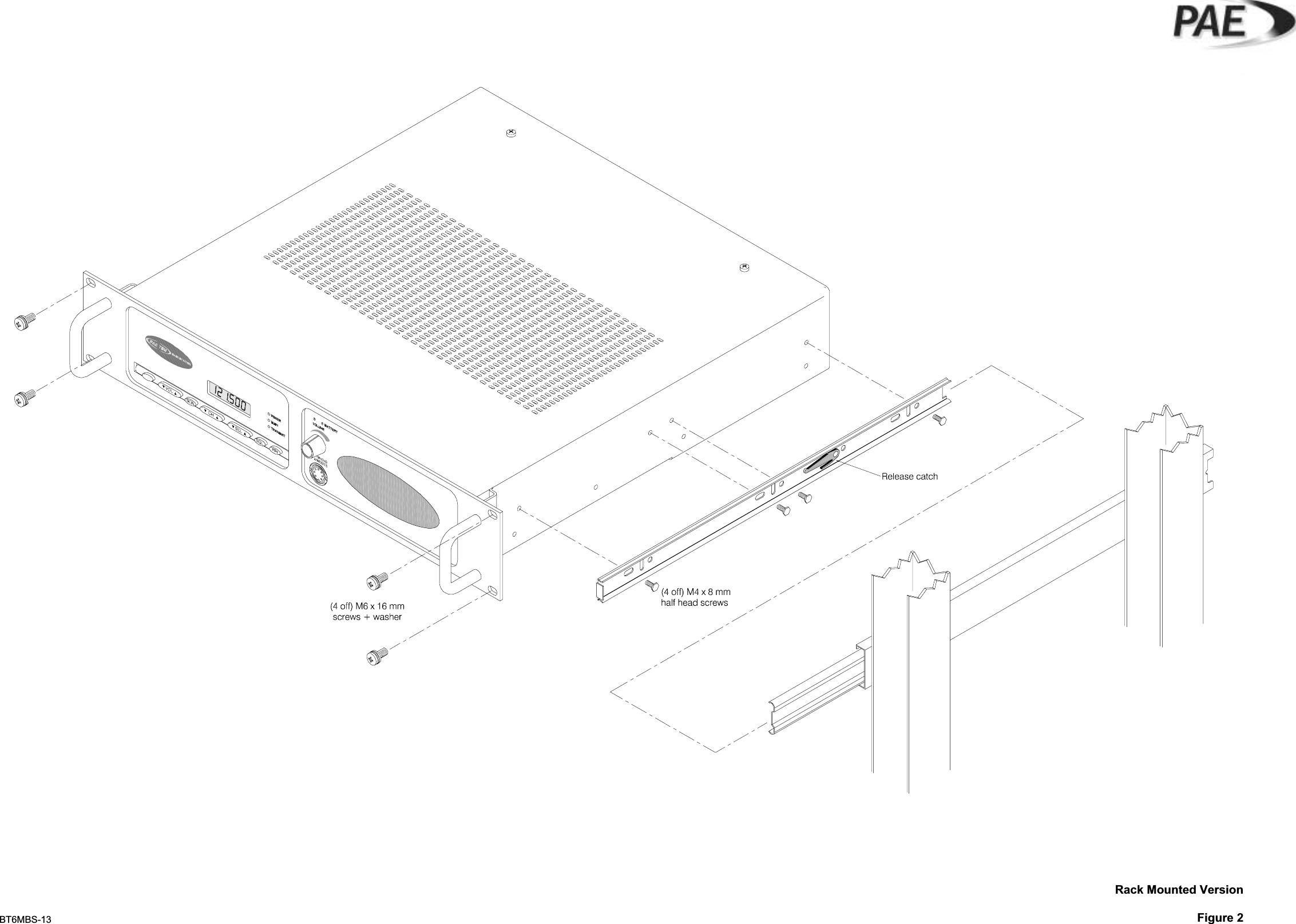
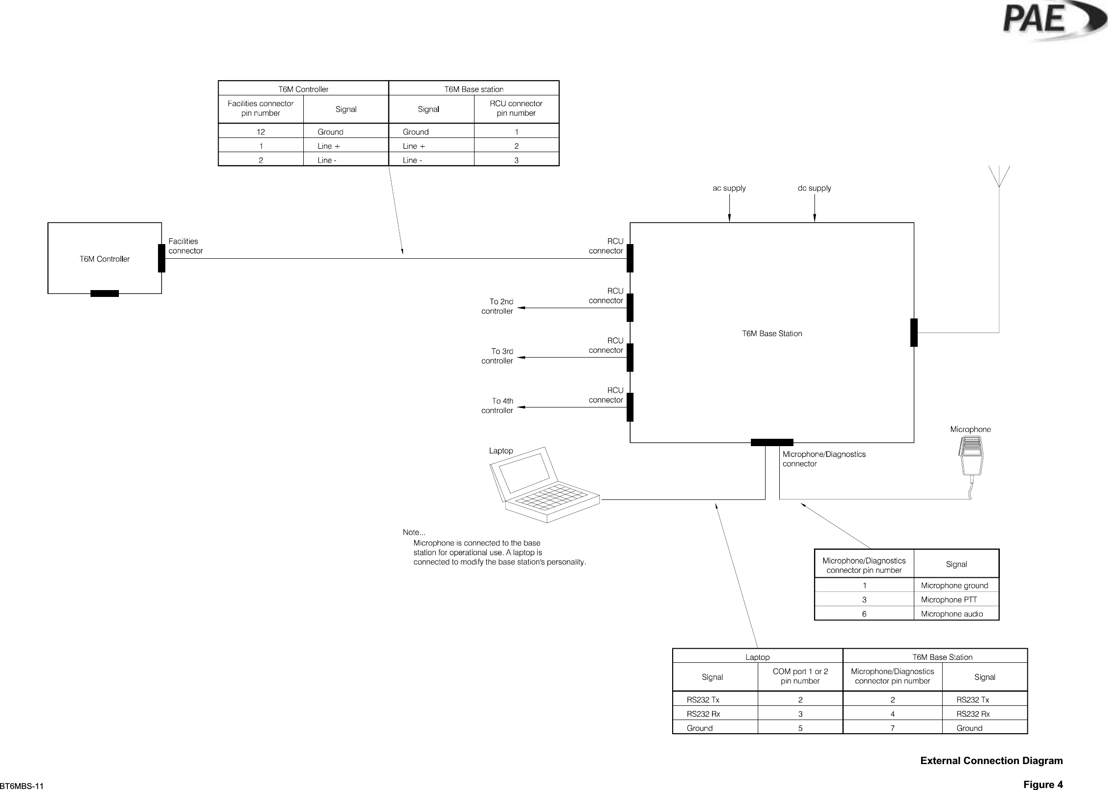
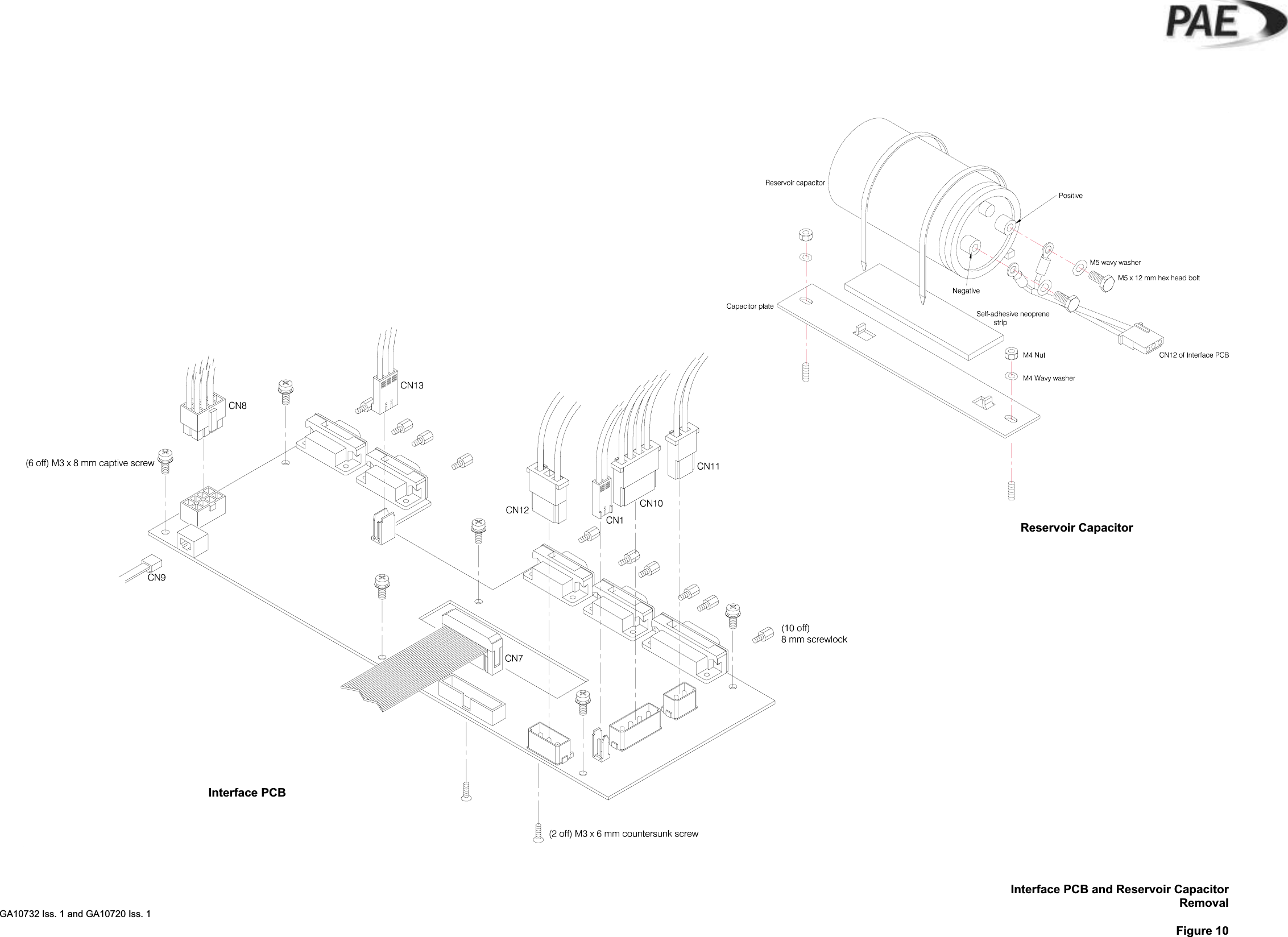
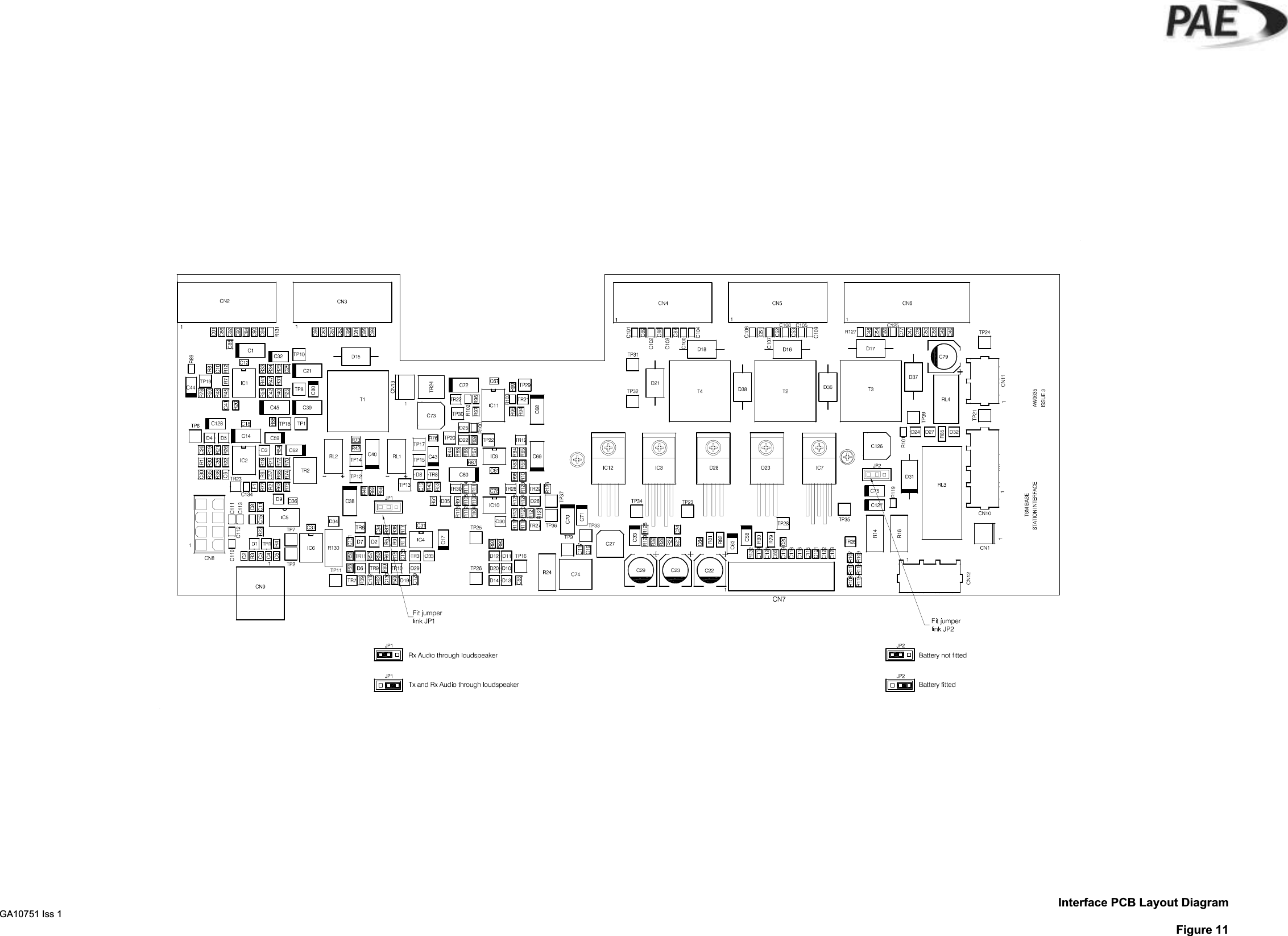
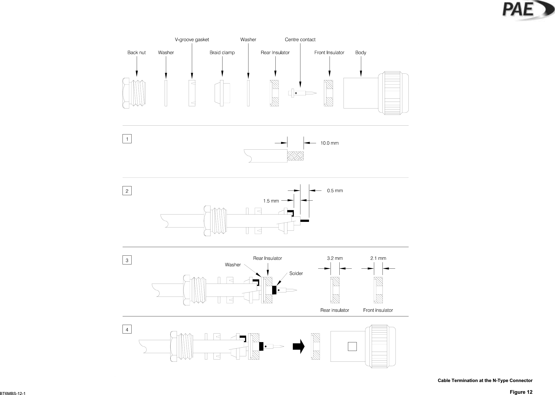
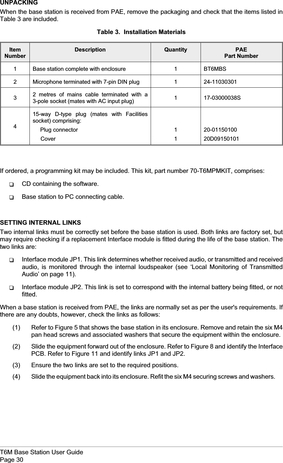
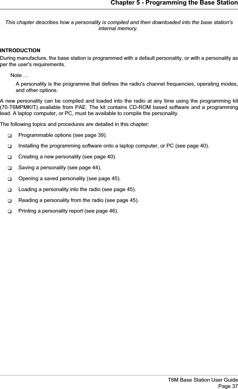
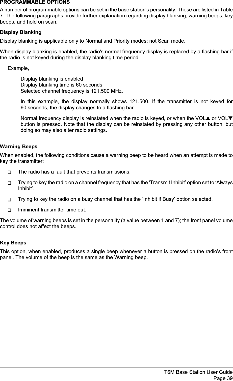
![Chapter 4 - InstallationThe instructions in this chapter should be followed, in the order given, to install the T6M base station.INTRODUCTIONWarning. Lethal Voltages!The instructions given in this chapter involve connecting lethal voltages to theequipment. The instructions, therefore, must be carried out only by suitably qualifiedpersonnel.Warning. Unauthorized Modifications!Changes, or modifications, made to this equipment that are not expressly approved byPark Air Electronics, or parties authorized by Park Air Electronics, could void the user’sauthority to operate the equipment.Warning. Antenna Radiation!The antenna used with this radio equipment must be installed such that the resultantradiated field strength is below 10 W/m²in areas normally accessible to personnel.Installing the base station involves the following operations. Each operation is detailed in this chapter ofthe user guide.qUnpacking and checking the installation kit is complete.qSetting (if necessary) internal links.qSiting the base station.qConnecting one, or more, RCUs to the base station (if required).qConnecting an antenna.qConnecting the base station chassis to earth.qConnecting the microphone (or a microphone/headset).qConnecting external facilities (if required) to the base station.qConnecting a dc input supply (if required).qConnecting a mains supply (if required).qConnecting a PC, or laptop, so that the base station's personality can be modified.T6M Base Station User GuidePage 29Before the base station is put into operational service, the required ‘personality’ information should beprogrammed in. This information, includes channel frequencies and operating modes.When a T6M base station is received from PAE, the personality is either:qA personality programmed to the user's specific requirements.or,qA default personality that covers the 760 channels (25 kHz spaced) available in the VHFaeronautical frequency band. No frequencies are allocated to the Priority list, and no scangroups are set.A programming kit is available from PAE. This allows a new personality to be programmed and downloaded.The base station does not have to be removed from its installed position to download a new personality.[Note that operation using 8.33 kHz channel spacing is not currently allowed within the USA.]](https://usermanual.wiki/Park-Air-Systems/BT6MBS/User-Guide-120544-Page-29.png)
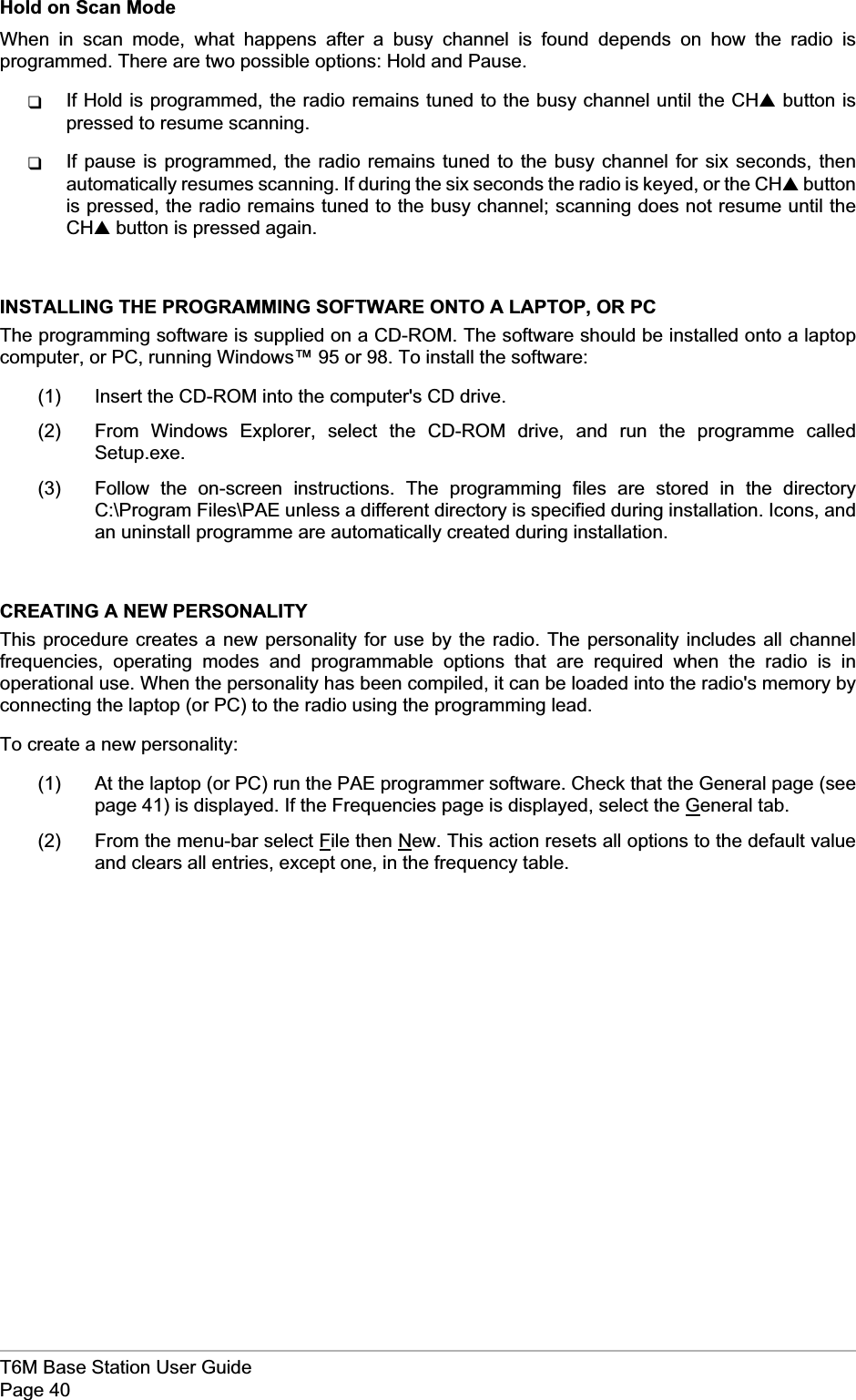
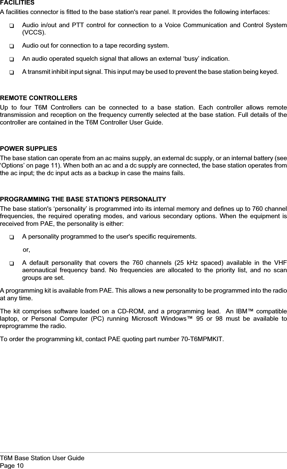
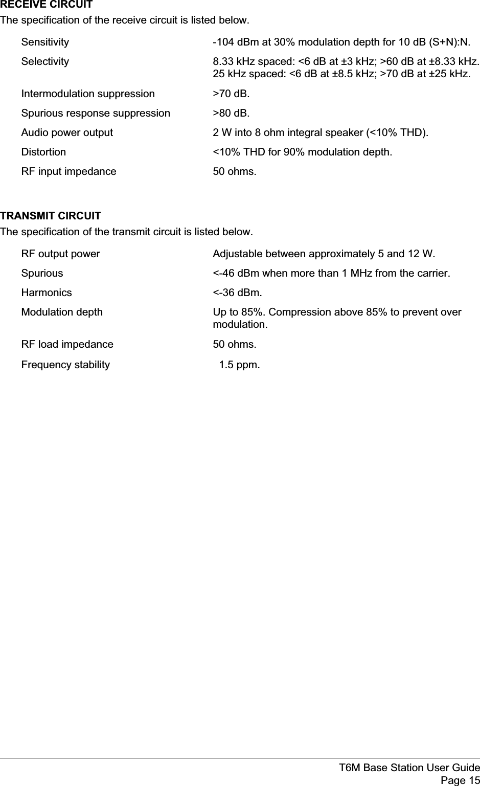
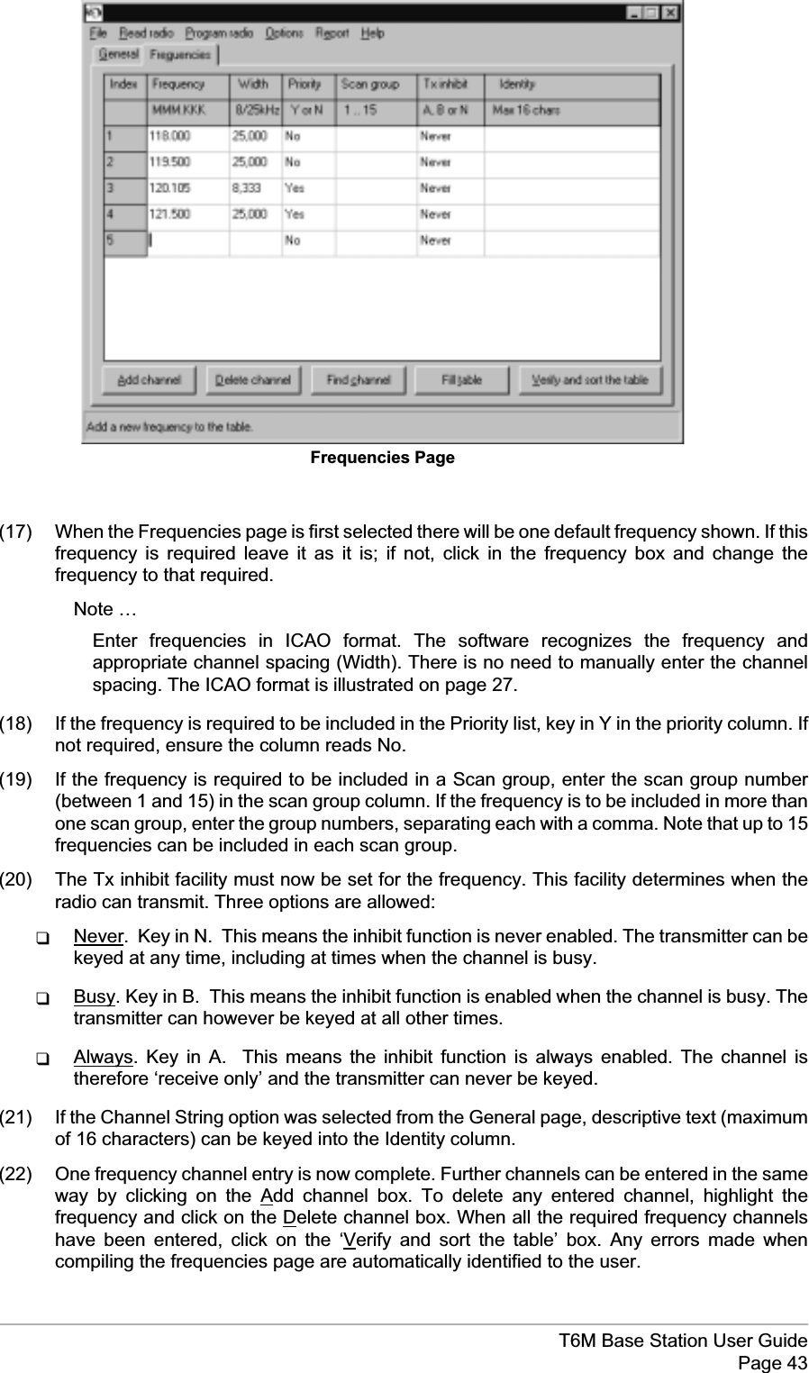
![(3) Use Channel Strings.Decide if you wish to store descriptive text for any of the channelfrequencies that will be programmed. If you do, use the mouse to ensure the box is checked.If you do not wish to use this facility, use the mouse to ensure the box is empty.Notes …If the Use Channel Strings facility is selected, the maximum number of channelfrequencies that can be stored is reduced from 760 to 400.Descriptive text is shown on the frequency list within this programme; it is not displayedat the radio.T6M Base Station User GuidePage 41General Page[Note that the status line at the bottom of the page displays help messages when the mouse pointer is placedover a programmable option.]](https://usermanual.wiki/Park-Air-Systems/BT6MBS/User-Guide-120544-Page-41.png)
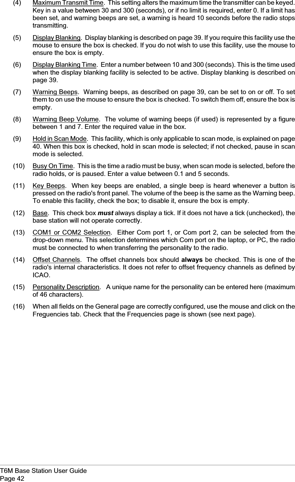

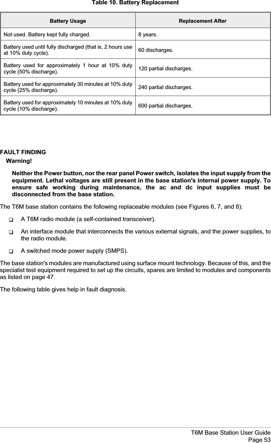
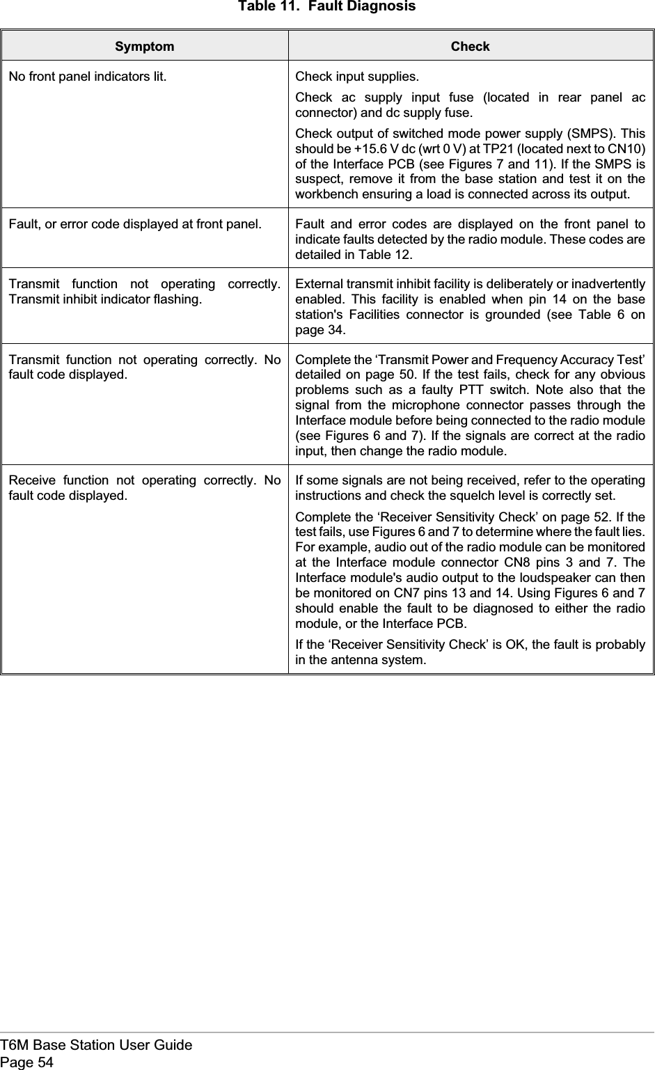
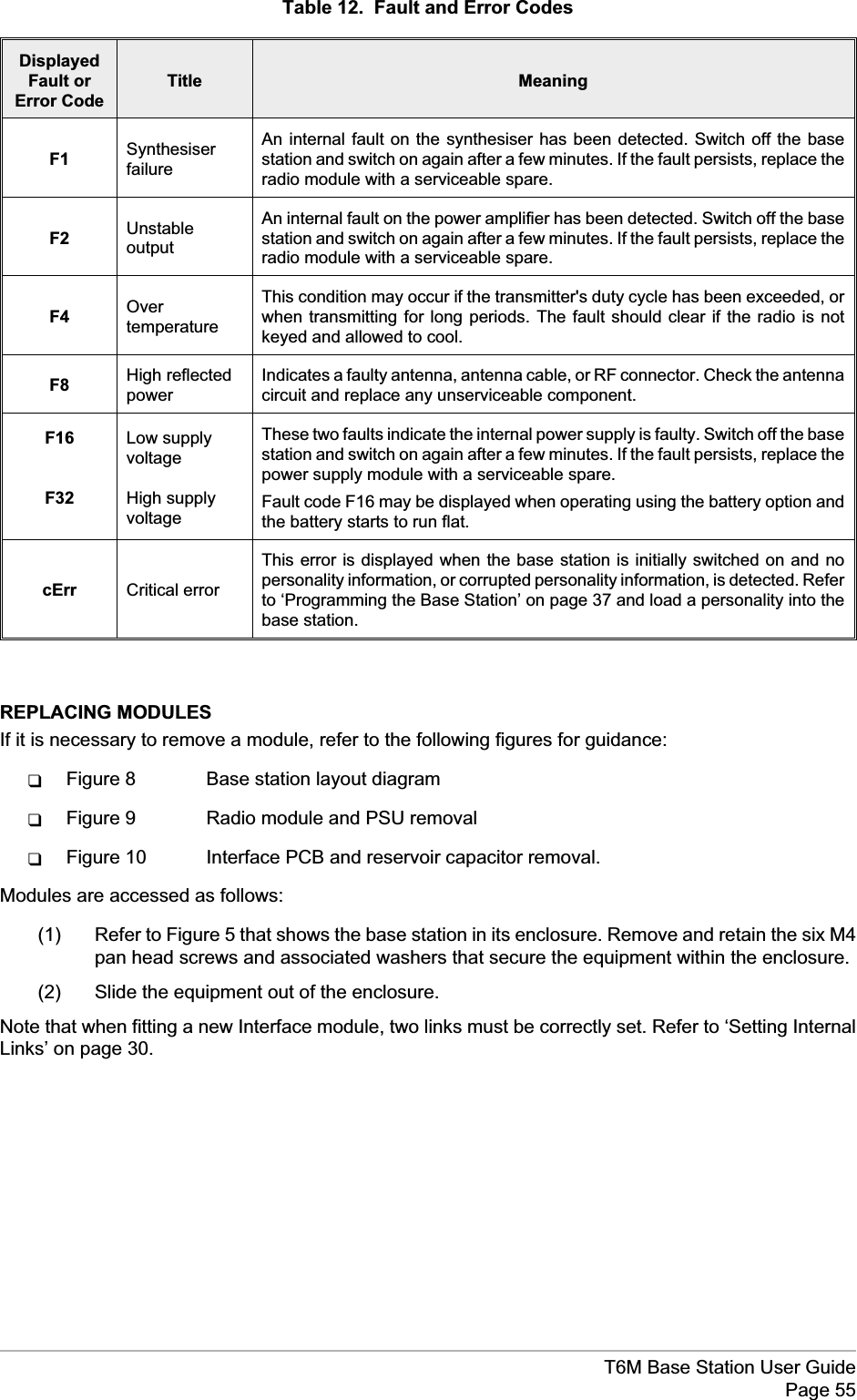
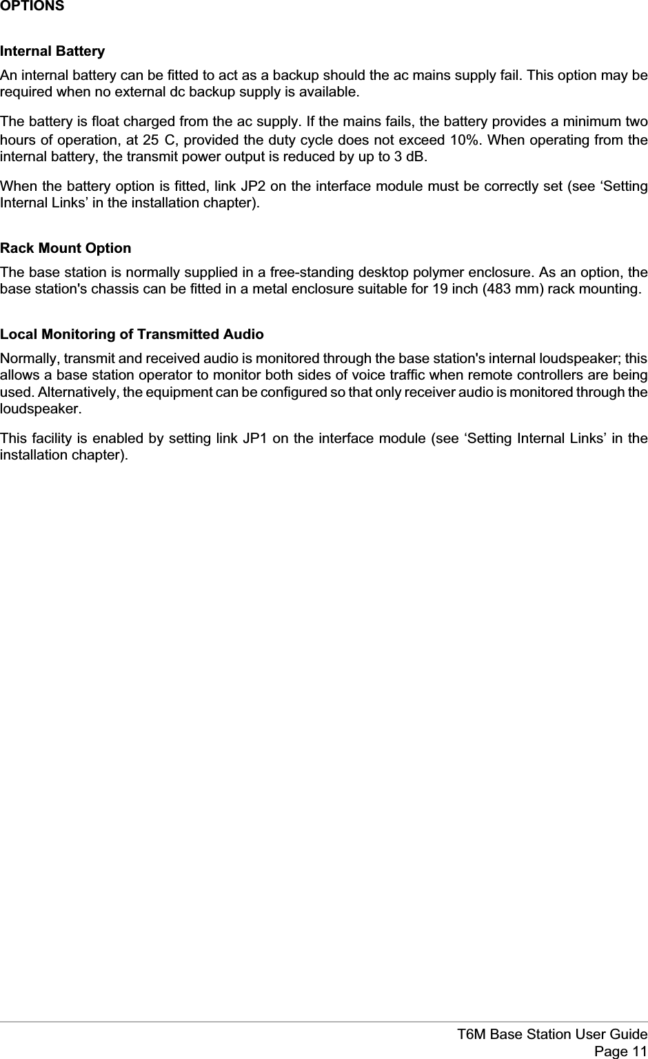
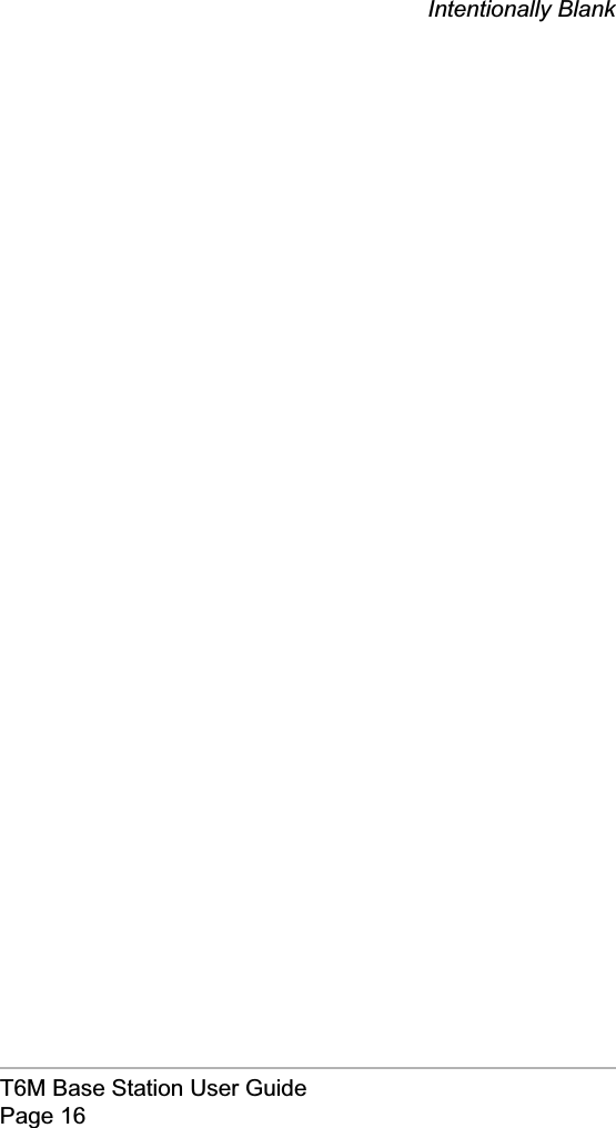
![Chapter 7 - MaintenanceThis chapter details the scheduled maintenance required by the T6M base station.It also provides fault finding guidance.SCHEDULED MAINTENANCEScheduled maintenance to the T6M base station involves the following checks:(1) Transmit power and frequency accuracy test. This check should be carried out annually.(2) Receiver sensitivity check. This check should be carried out annually.(3) Battery replacement (applicable only to base stations fitted with the internal battery option).The life of the battery depends upon its usage; refer to ‘Battery Replacement’ on page 52.Test Equipment RequiredThe test equipment necessary to complete the scheduled maintenance is listed in Table 8.Table 8. List of test equipmentItem Description1 Through-line wattmeter.2 20 dB attenuator (>15 W continuous power rating).3 VHF Frequency counter.4 RF signal generator.5 AF wattmeter.6 Test lead for connecting the base station to the AF wattmeter. [See next heading.]Test LeadThe test lead (Table 8, item 6) connects the base station to the AF wattmeter during receiver sensitivitytests. The lead connections are detailed in Table 9.Table 9. Test Lead Connections7-Pin DIN Plug(connects to base station'sMicrophone connector)AF Wattmeter ConnectorPin 5, receiver audio monitor InputPin 7, earth 0 VT6M Base Station User GuidePage 49](https://usermanual.wiki/Park-Air-Systems/BT6MBS/User-Guide-120544-Page-49.png)