Park Air Systems BT6M VHF Airband mobile transceiver User Manual PAE Header
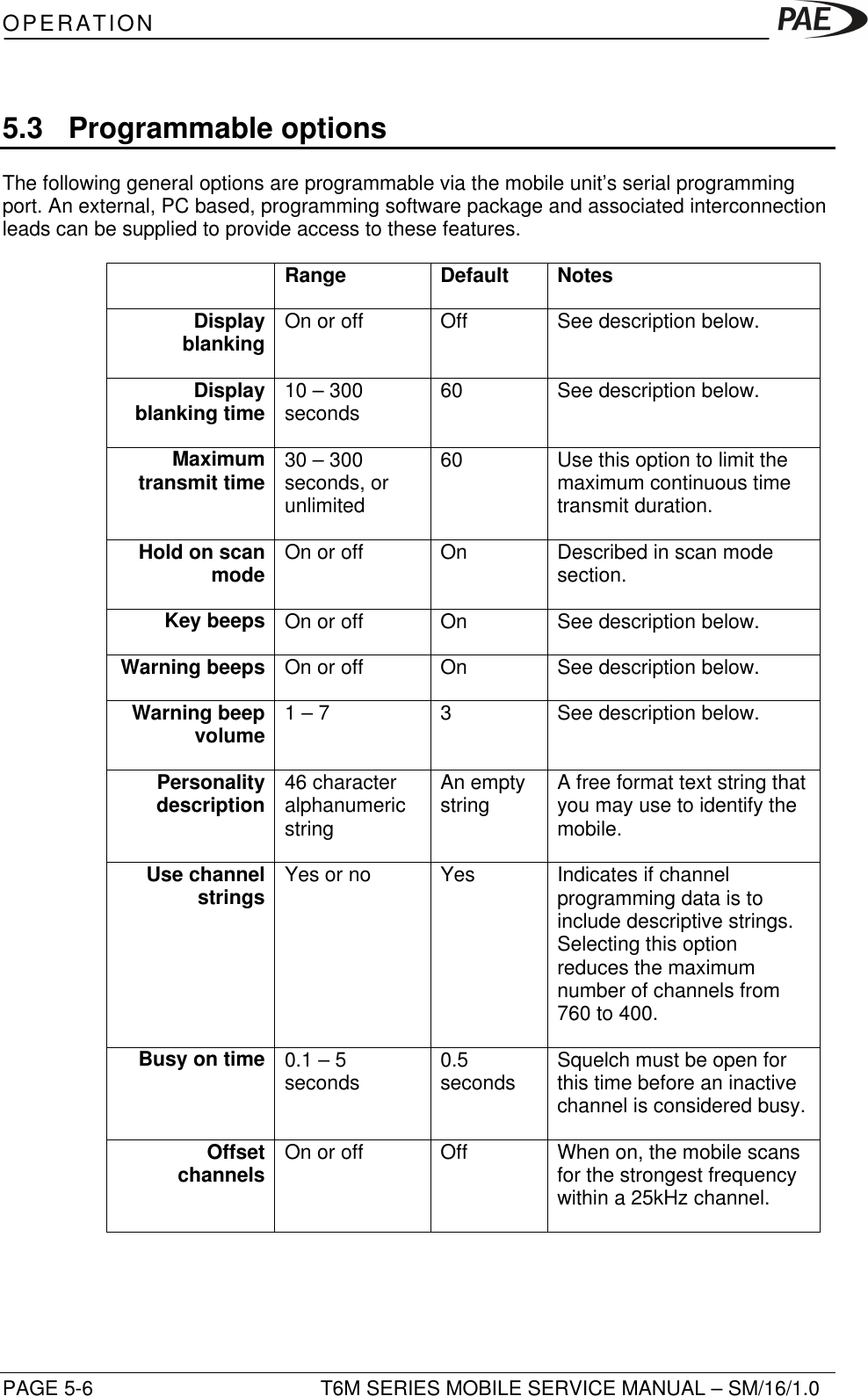
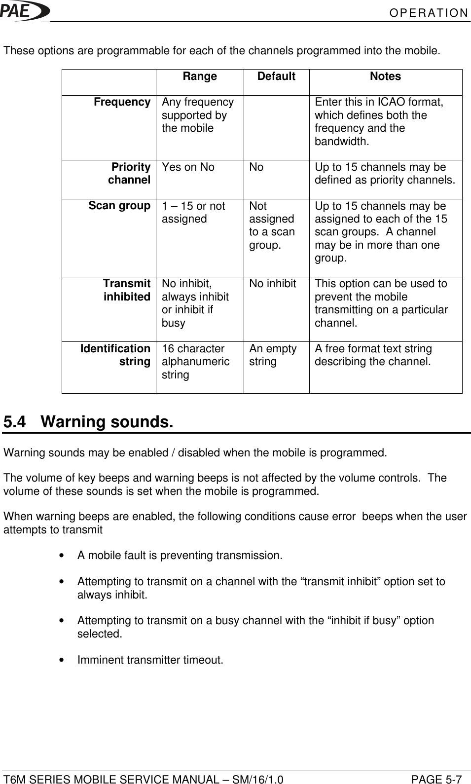
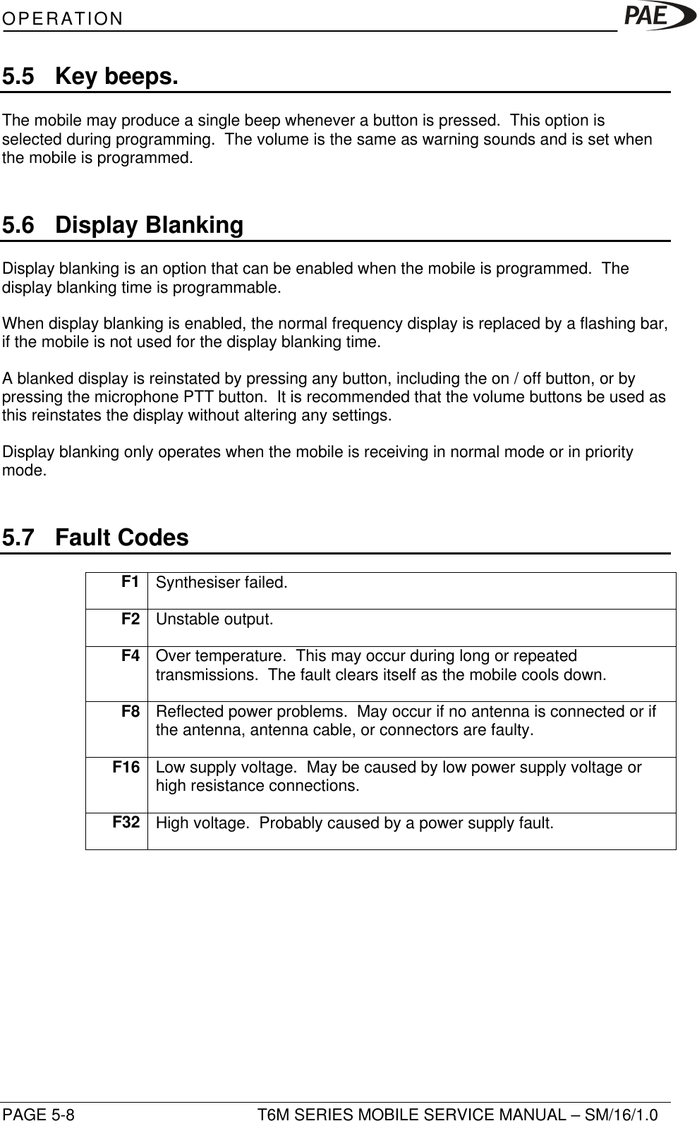
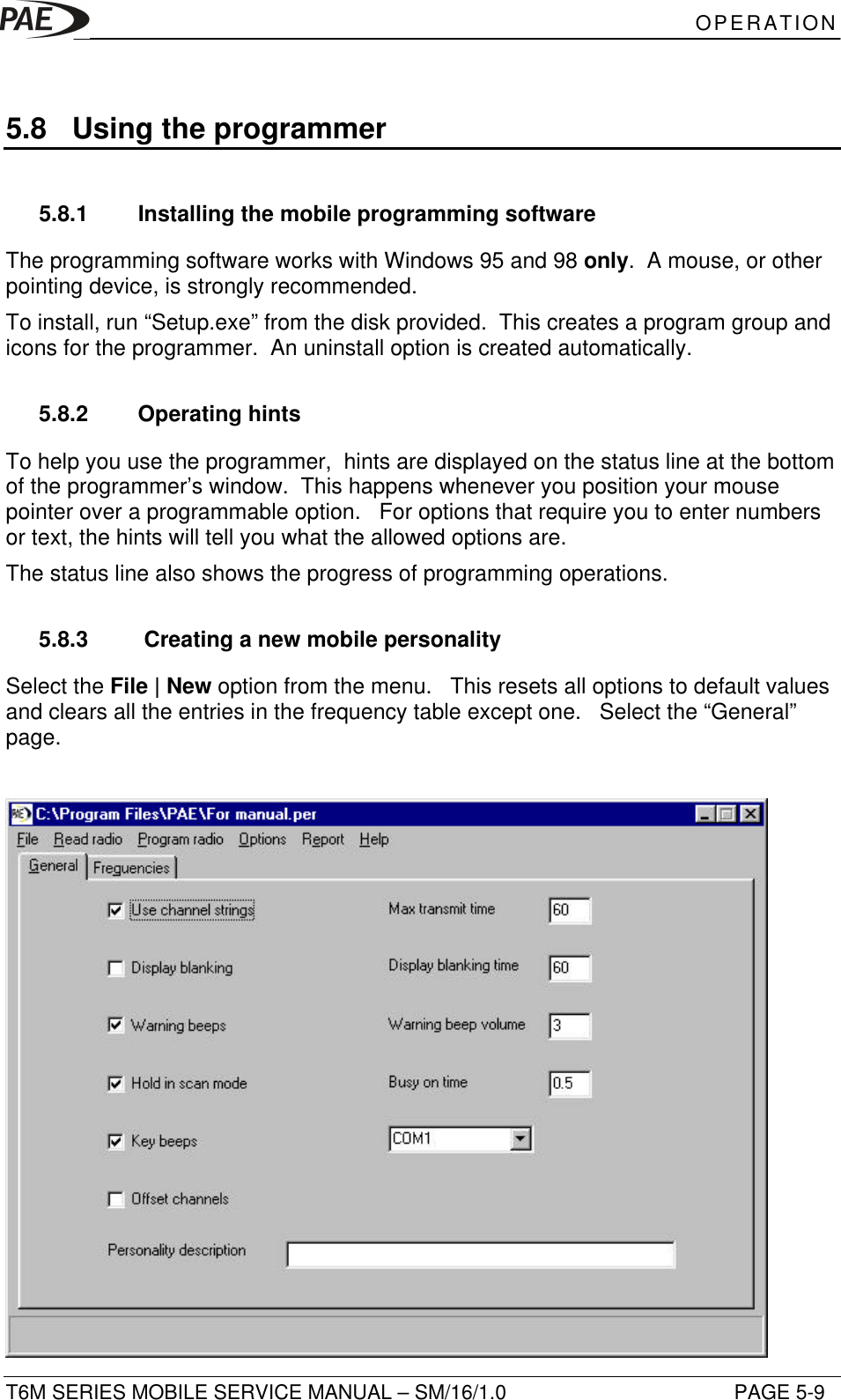
Park Air Systems Limited VHF Airband mobile transceiver PAE Header
UserManual.wiki
>
Park Air Systems
>
BT6M User Manual
Exhibit D User guide
Navigation menu
Upload a User Manual
Namespaces
Wiki Guide
HTML
PDF
Info
Views
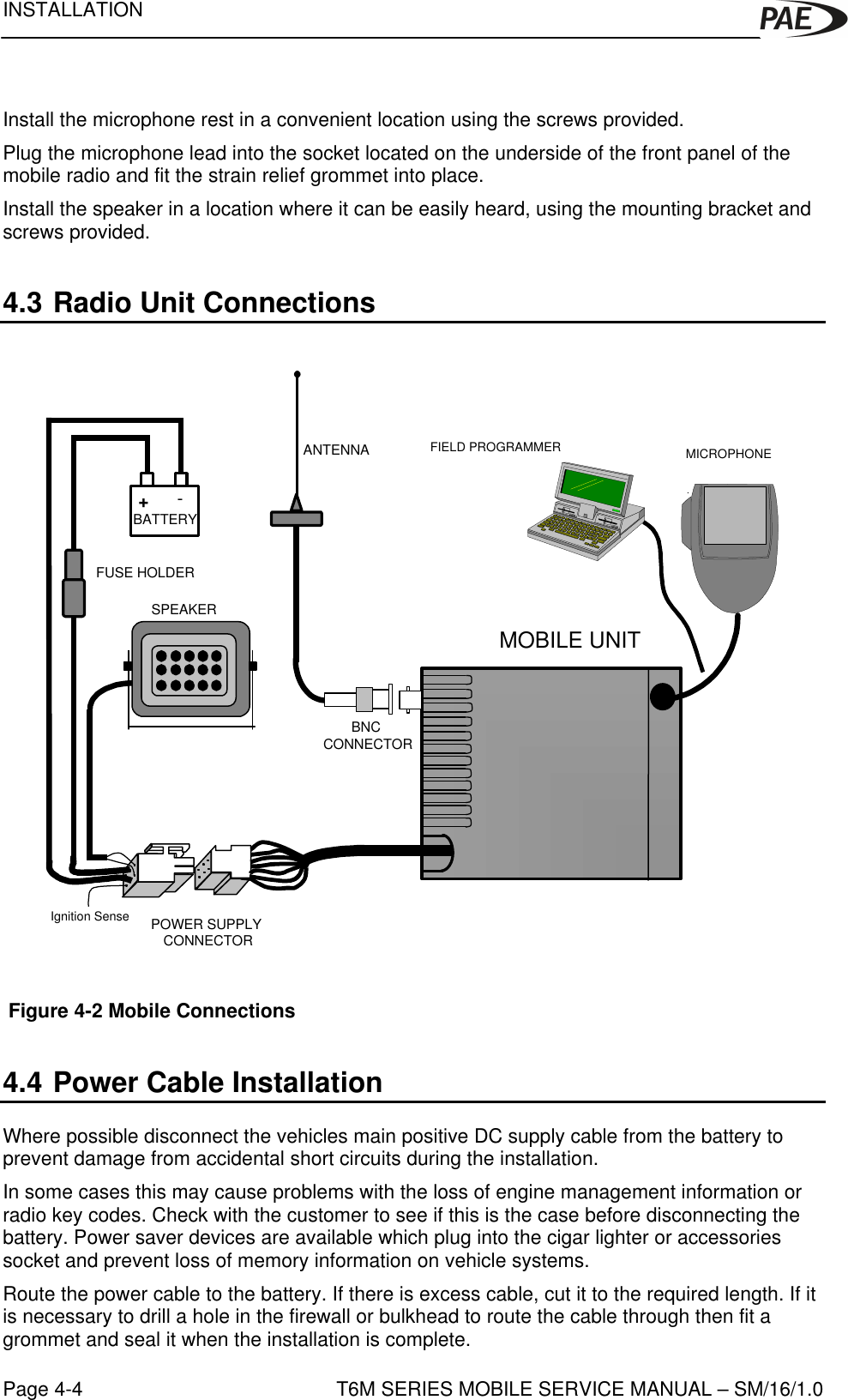
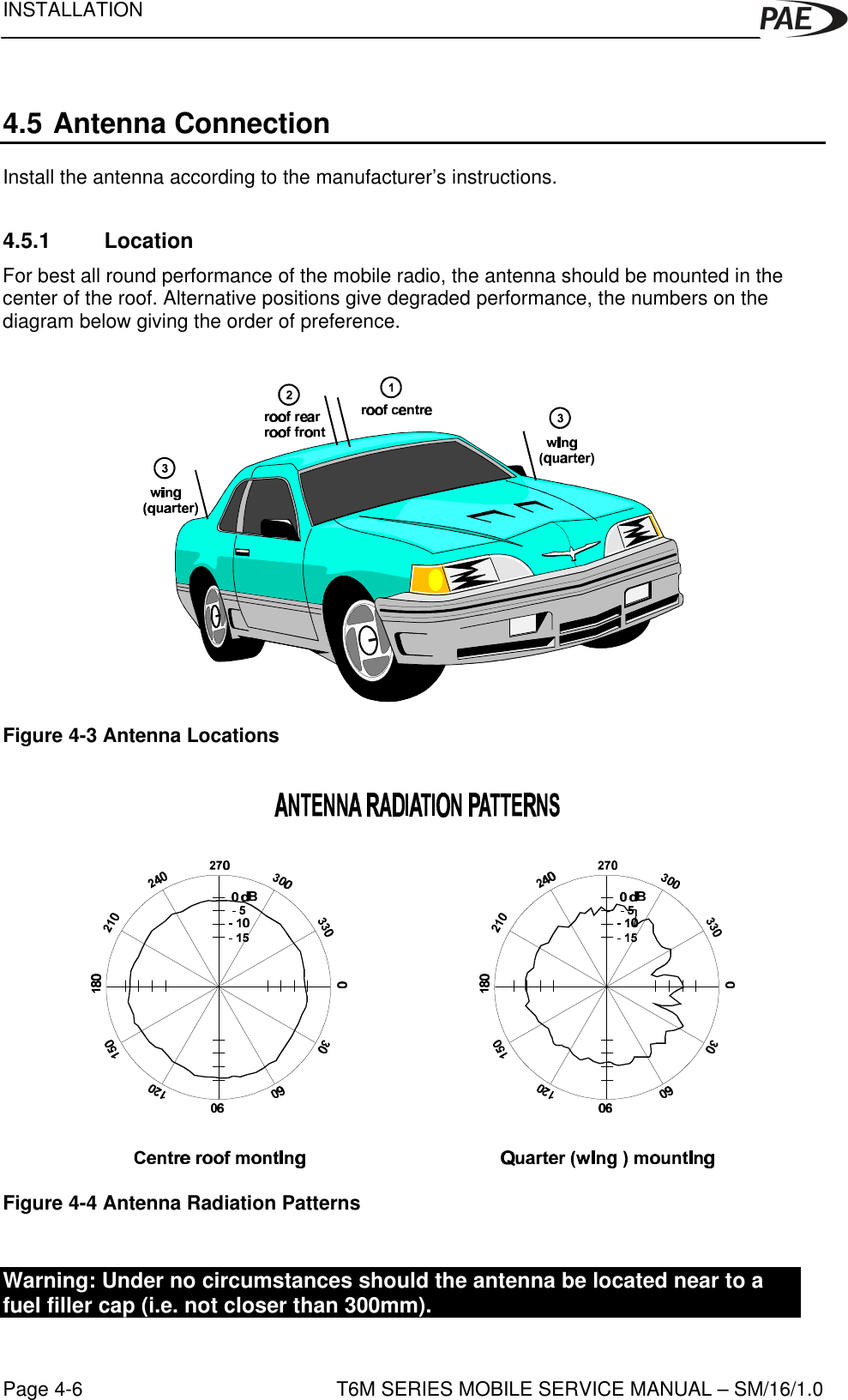
User Manual
Discussion / Help
Navigation