Park Air Systems B6525MDR Multimode VHF Ground to Air Transceiver User Manual MDR
Park Air Systems Limited Multimode VHF Ground to Air Transceiver MDR
User Manual
6525 Multimode Digital Radio
User Documentation
Draft

31-3MDR00HB Page 2
Draft
Handbook Title: 6525 Multimode Digital Radio User Documentation
Handbook Part Number: 31-3MDR00HB
Handbook Version: Draft
Date of Issue: June 2007
Published By: Park Air Systems
Northfields
Market Deeping
Peterborough PE6 8UE
England
Telephone: From UK, 01778 345434
From outside UK, 44 1778 345434
Fax: From UK, 01778 342877
From outside UK, 44 1778 342877
www.parkairsystems.com
Errata
Any errors found in this handbook are promulgated through the Park Air FTP network. Any
user can access this information by logging on to:
ftp.parkairsystems.com
When logged on, select the public (Pub) folder, then the Handbook Errata Sheets folder,
and then select the required equipment model.
[Adobe Acrobat™ must be loaded on your PC to use this facility]
31-3MDR00HB Page 3
Draft
Health and Safety
Warnings
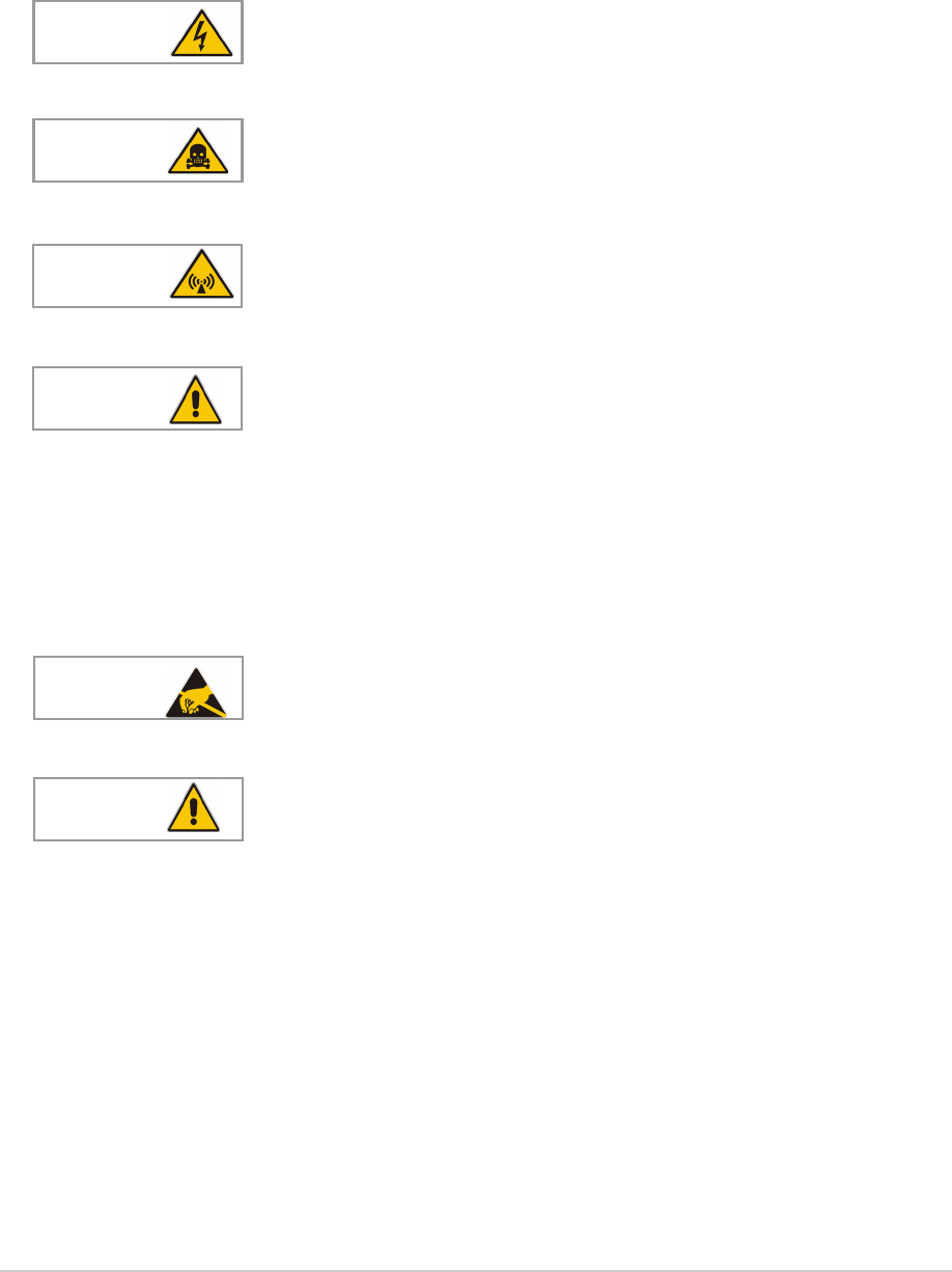
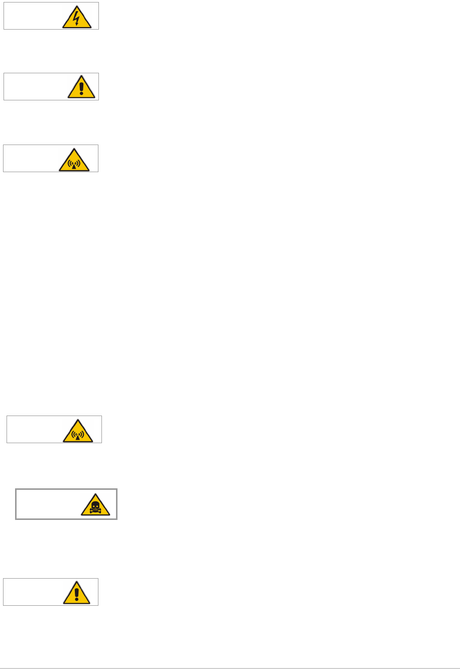
A warning is used to indicate possible danger to personnel. Throughout Park Air handbooks, warnings
are indicated by the following symbols:
Cautions
A caution is used to indicate possible danger to the equipment.
Indicates electrical danger to personnel.WARNING
Indicates a hazardous material.
WARNING
Indicates a non-ionizing radiation hazard.
WARNING
Indicates a specified danger to personnel.
WARNING
Indicates the presence of electrostatic sensitive devices (ESSD). Caution
Indicates a specified danger to the equipment. Caution
31-3MDR00HB Page 4
Draft
Health and Safety (Continued)
Specific Warnings Applicable to the MDR
The instructions given in this documentation involve connecting dangerous voltage to the MDR.
Installation must be carried out only by suitably qualified personnel.
This equipment must be earthed. The earth terminal of the ac connector must be used as the safety
earth.
The antenna used with the MDR must be installed such that the resultant radiated field strength is
below 10 W/m² in areas normally accessible to personnel.
The RF field strength from the antenna can be predicted from the equation S=1.4PG/4πR2
[Where S = power density; P = power input to antenna; G = antenna gain; R = distance
to centre of radiation and 1.4 = multiplication factor for average power based on a
modulation index of 90%.]
Based on this formula a 2 dBi antenna, the predicted safe distance from the centre of radiation would
be approximately 0.75 m for a field strength of 10 W/m2 (1 mW/cm2).
This meets the requirements of Health Canada Safety Code 6 for RF and microwave exposed
workers. For persons not classed as RF and microwave workers and including the general public
the limit is 2 W/m2 (0.2 mW/cm2) which increases the minimum safe distance to 1.7 m.
Further information on calculating the field strengths and power levels can be found in Health
Canada Safety Code 6 'Limits of Human Exposure to Radiofrequency Electromagnetic Fields in the
Frequency Range 3 kHz to 300 GHz', and also in FCC document OET Bulletin 65.
Ensure an antenna, or dummy load, is connected before switching on the MDR. There is high RF
voltage present at the antenna connector when the radio is keyed.
Although no instructions in this documentation involve removing any equipment covers, users
should be aware that the RFPA output transistors contain Beryllium.
During installation an MDR may have to be lifted, possibly to head height, to fit onto telescopic slides.
At least two people should be used to lift the equipment. Failure to use sufficient people when lifting
equipment can result in personal injury.
WARNING Dangerous Voltage
WARNING Earth Connection
WARNING Antenna Radiation
WARNING Antenna Radiation
Beryllium Hazard
WARNING
WARNING Heavy Item

31-3MDR00HB Page 5
Draft
Disposal
This product is covered by the European Directive 2002/96/EC.
It must not be disposed of in domestic waste.
Disposal should be made using designated collection facilities
appointed by the government or local authority in your area.

31-3MDR00HB Page 6
Draft
List of Abbreviations
Aamp
ac alternating current
ACARS aircraft communications, addressing
and reporting system
AM amplitude modulation
BIT built-in test
C celsius
dB decibel
dBm power ratio in decibel (dB) referenced
to one milliwatt (mW)
dc direct current
ESD electrostatic sensitive devices
Fig figure
Hz hertz
kg kilogramme
kHz kilohertz
LCD liquid crystal display
mmetre
mA milliamp
MDR multimode digital radio
MHz megahertz
mm millimetre
ms milli-second
mW milliwatt
PA power amplifier
ppm parts per million
PTT press to transmit
RFPA radio frequency power amplifier
s second
Vvolt
VDL VHF data link
VHF very high frequency
VSWR voltage standing wave ratio
Wwatt
31-3MDR00HB Page 7
Draft
Approvals and Standards 6525 Multimode Digital Radio
The equipment is designed to meet the following requirements:
RoHS Directive 2002/95/EC
WEEE Directive 2002/96/EC
ICAO Annex 10 Vol lll Part 1 Chapter 6
EN 301 841-1 Electromagnetic compatibility and Radio spectrum Matters (ERM); VHF air-ground
Digital Link (VDL) Mode 2; Technical characteristics and methods of measurement for
ground-based equipment; Part 1: Physical layer and MAC sub-layer
EN 300 676 Electromagnetic compatibility and Radio spectrum Matters (ERM); Ground-based
VHF hand-held, mobile and fixed radio transmitters, receivers and transceivers for the VHF
aeronautical mobile service using amplitude modulation; Technical characteristics and methods
of measurement.
Approvals have been granted against the following:
Safety approval to EN60950-1, CAN/CSA-C22.2 No. 60950 and UL 60950
FCC Rules 47CFR Parts 15 and 87
Technical Acceptance under Industry Canada, reference Radio Standard Specification RSS141
CE approval under the R&TTE Directive 1999/5/EC.
0336
!
RoHS
2002/95/EC
FCC ID; C8L 6525MDR
FCC / Industry Canada Statement
This device has been tested and found to comply with the limits for a Class B digital device, pursuant
to part 15 of the FCC Rules. These limits are designed to provide reasonable protection against
harmful interference in a residential installation.
This equipment generates, uses and can radiate radio frequency energy and, if not installed and used
in accordance with the instructions, may cause harmful interference to radio communications.
However, there is no guarantee that interference will not occur in a particular installation.
If this equipment does cause harmful interference to radio or television reception, which can be
determined by turning the equipment off and on, the user is encouraged to try to correct the
interference by one or more of the following measures:
Reorient or relocate the receiving antenna.
Increase the separation between the equipment and the receiver.
Connect the equipment into an outlet on a circuit different from that to which the receiver is
connected.
Consult the supplier or an experienced radio/TV technician for help.
Operation on 8.33 kHz channel spacing is prohibited under the current regulations
of Industry Canada and the FCC.

31-3MDR00HB Page 8
Draft
Intentionally Blank

Contents
Page
31-3MDR00HB Page 9
Draft
Overview 11
Introduction 12
Operating Modes 12
MDR Applications 13
Hardware Configuration 13
Software Configuration 13
Specification 15
MDR Operating Characteristics 16
Dimensions and Weight 16
Input Supply Requirement 16
Environmental 16
Operation 17
Controls and Indicators 18
Introduction 18
Controls and Indicators 18
Ready Indicator 18
Alarm Indicator 18
Receive Indicator 18
Transmit Indicator 18
Scroll/Select Switch and LCD 19
Connectors 19
Reference Connector 19
Headset/Microphone/Diagnostics Connector 19
Switching On and Setting the Operating Parameters 21
Using the Scroll/Select Switch 21
Screen Protocol 21
Switching On 22
Selecting an Operating Mode 23
Selecting the Operating Frequency 24
Storing and Recalling Frequency Channels 25
Setting Band Edges 27
Setting Parameters 29
Downloading Software Fills 35
Installation 37
Introduction 38
Fuses and Connectors 39
Initial Inspection of the MDR 39
Fitting an MDR into an Equipment Cabinet 40
Rear Panel Interfaces 41
Ethernet Connector 42
Facilities Connector 43
Auxiliary Connector 45
Connecting the Chassis Stud 46
Connecting an Antenna 46
Checking the ac Input Fuse 47
AC Supply Connection 47

31-3MDR00HB Page 10
Contents (continued)
Page
Draft
Maintenance 49
Maintenance Policy 50
Unscheduled Maintenance 50
Scheduled Maintenance 50
Cleaning the Equipment 50
Security of External Connections 50
Checking the MDR’s Internal Reference Frequency 51
Initiating an Interruptive BIT Test 52
Removing and Refitting the Cooling Fan 54
Draft
Overview
31-3MDR00HB Page 12 Overview
Draft
Introduction
This documentation describes the Park Air 6525 Multimode Digital Radio (MDR). The MDR is a VHF
transceiver operating in the aeronautical frequency band between 118 and 136.975 MHz. The maximum
transmit output power is 25 watts.
The MDR can be used as a conventional AM-Voice transceiver, or can operate as a subsystem of the
Aircraft Communications, Addressing and Reporting System (ACARS) and the VHF Data Link (VDL)
air-ground communication systems.
Fig 1 6525 Multimode Digital Radio (MDR)
Operating Modes
Operating modes are software controlled. A 6525 MDR can be loaded with any two of the four available
software fills shown in Fig 2. All four software fills are available to download through the user’s network.
Fig 2 Operating Modes
AM DigitalAM Analogue
ACARS ACARS
VDL
Mode 2
AM-Voice
6525 MDR
(requires an
external modem)
(uses modem
within the MDR)
31-3MDR00HB Page 13 Overview
Draft
MDR Applications
In addition to operating in a conventional AM-Voice mode, the MDR can operate in two VHF air-ground
data link services: ACARS and VDL mode 2.
ACARS is a low-speed data link in wide use throughout the world, operating at 2.4 kbits per second using
MSK modulation.
VDL mode 2 is a higher bandwidth, connection orientated service, operating at 31.5 kbits per second
using D8PSK modulation.
Hardware Configuration
The product model is: 6525 MDR.
The part number is: B6525.
A hardware configuration label is fixed to the MDR’s rear panel. The label shows the model, part number,
serial number and modification status. An example label is shown in Fig 3.
Fig 3 Hardware Configuration Label
Software Configuration
The part order number is TBD (customer specific). This number encompasses the hardware part number
detailed above, fitted with the software detailed below.
Any two of the four available software fills can be stored in the MDR at any one time. A software
configuration label, as shown in Fig 4, is fixed to the MDR’s top cover. This label details the part numbers
for the four mode software fills, and the permanently installed Ethernet software.
Fig 4 Software Label
Model:
Part No:
S / No:
Mod Record:
6525 MDR
B6525
1M2345
1 2 3 4 5 6 7 8 9
Park Air Systems Ltd England
PAE
Software Configuration
Part Order No. TBD (customer specific)
Software Mode Part No.
Fill * AM Voice TBD (customer specific)
Fill * AM Analogue ACARS TBD (customer specific)
Fill * AM Digital ACARS TBD (customer specific)
Fill * VDL Mode 2 TBD (customer specific)
Interface Ethernet TBD (customer specific)
*Only 2 are stored in the radio at any one time
Intentionally Blank
Draft
Specification

31-3MDR00HB Page 16 Specification
Draft
MDR Operating Characteristics
Frequency range Between 118 and 136.975 MHz
Number of channels 100
Channel spacing 25 kHz (all modes)
8.33 kHz (Am-Voice mode only)
Modulation modes ACARS 13K0A2D
VDL Mode 2 14K0G1D
AM-Voice (25 kHz) 6K00A3E
AM-Voice (8.33 kHz) 5K00A3E
Frequency stability Better than 1 ppm within permissible environmental conditions
Dimensions and Weight
The dimensions and weight of the MDR are:
Width 483 mm (19 inches)
Depth 450 mm (17.8 inches)
Height 88.9 mm (3.5 inches).
Weight 12.5 kg (27.5 pounds)
Input Supply Requirement
ac input supply Between 90 and 264 Vac, 47 to 63 Hz
ac power consumption Tx, less than 400 VA (250 VA typical)
Rx, less than 70 VA
Environmental
Temperature range 0 to +40°C operating
-20 to +60°C non-operating
Ventilation The MDR is cooled by a temperature controlled fan. When the MDR is
switched on, the fan runs at full speed for a short period before coming
under temperature control
Warm up time Less than 30 seconds
Draft
Operation

31-3MDR00HB Page 18 Operation
Draft
Controls and Indicators
Introduction
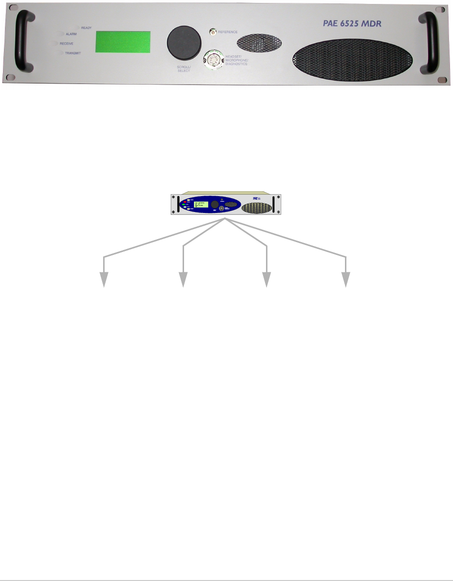
This topic describes the MDR’s front panel (see Fig 5) controls, indicators and connectors.
Fig 5 MDR Front Panel
Controls and Indicators
Ready Indicator
A green indicator that lights when the MDR is ready for use and no BIT faults have been detected.
Alarm Indicator
A red indicator that either flashes, or lights, when a BIT fault has been detected. BIT indications are
classified as either Alerts or Alarms.
If an ‘alert’ condition is detected, the Alarm indicator flashes, the Ready indicator remains lit, and the
MDR remains operational. A BIT ‘alert’ is indicated if:
The MDR’s RF output power has reduced from its setting by more than 1 dB but not more than
3dB
The supply volts falls below 21.6 V
The RF PA temperature has exceeded 80oC.
Any other BIT condition results in an alarm. When detected, the Alarm indicator lights and the Ready
indicator becomes unlit; the MDR cannot be used.
When the Alarm indicator flashes, or is lit, the front panel display indicates the nature of the Alert or Alarm
Receive Indicator
An amber indicator that lights as follows:
In AM-Voice mode When a signal above the squelch threshold is received, or when
the squelch is defeated.
In VDL 2 mode Lights on Sync and remains lit until the end of message.
In AM Analogue ACARS mode Lit when a signal is received.
In AM Digital ACARS mode Lights on Sync and remains lit until the end of message.
Transmit Indicator
An amber indicator that lights when the transmit circuit is keyed and producing output power.
31-3MDR00HB Page 19 Operation
Draft
Scroll/Select Switch and LCD
The Scroll/Select switch is used in conjunction with the LCD to select most of the MDR's operational
settings. During normal operation, the LCD displays the Main screen. Detailed information regarding the
Scroll/Select switch and LCD is given on page 21.
Connectors
Reference Connector
An SMB jack socket that allows a frequency counter to monitor the MDR's reference frequency. This
connector is used only for maintenance purposes. The instructions for checking and adjusting the
reference frequency are given in the Maintenance topic.
Headset/Microphone/Diagnostics Connector
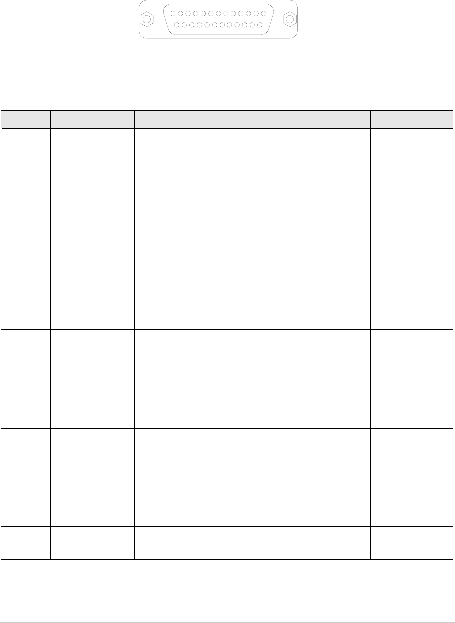
A dual purpose connector that allows either a headset/microphone, or a PC, to be connected to the MDR.
The connector is a 7-pin self-locking DIN socket; the pin-out is shown in Fig 6 and detailed in Table 1 for
the audio connections, and Table 2 for the PC connections.
A microphone/headset is used to enable the MDR to be operated from the front panel in AM-Voice mode.
Fig 6 Headset/Microphone/Diagnostics Connector Pin-Out
Table 1 Headset/Microphone/Diagnostics Connector - Audio Connections
Pin
Number Signal Input or
Output Description
1 Microphone ground - 0 V.
3 Microphone PTT Input 0 V to PTT.
5 Sidetone/headset drive Output 0 to 3 V pk-pk.
6 Microphone input Input 2 to 35 mV rms on Passive setting and 8 to 140 mV rms
on Active setting to remain in VOGAD range.
7 Ground - 0 V.

31-3MDR00HB Page 20 Operation
Draft
Note:
PC connections are used for maintenance at Park Air. No instructions in this documentation
require the use of this port.
Table 2 Headset/Microphone/Diagnostics Connector - PC Connections
Pin
Number Signal Input or
Output Description
2 Transmit data Output RS232, 115200 baud, 8 data bits, 1 stop bit, no parity, no
handshaking.
4 Receive data Input RS232, 115200 baud, 8 data bits, 1 stop bit, no parity, no
handshaking.
7 Ground - 0 V.

31-3MDR00HB Page 21 Operation
Draft
Switching On and Setting the Operating Parameters
Using the Scroll/Select Switch
The Scroll/Select switch (referred to throughout this topic as the ‘Switch’) is used to leave the Main
screen and display the Control screen. Further use of the Switch displays various selection menus and
allows the required parameters to be set. The switch has three actions: it can be turned clockwise, anti-
clockwise, or momentarily pushed in.
Screen Protocol
The following protocol is applicable to all screens described in this document.
Main Screen During normal MDR operation, the Main screen, an example of which is shown
below, is displayed.
Switch Refers to the front panel Scroll/Select switch. The switch is turned clockwise to scroll
through fields from left to right, and from top to bottom. The switch is turned
anticlockwise to scroll through fields from right to left, and from bottom to top. The
switch is pressed to make a selection.
Time out If during any setting up procedure the Scroll/Select switch is not operated for
30 seconds, the display returns to the Main screen. If editing any parameter has not
been completed, the MDR stays on the original setting.
>> Indicates more fields are available other than those currently displayed. To access
those fields, turn the switch clockwise through the last displayed field.
<< Indicates more fields are available other than those currently displayed. To access
those fields, turn the switch anti-clockwise through the first displayed field.
Back When Back is selected, you are returned to the previous menu.
Exit When Exit is selected, you are returned to the Main screen.
F r e q 1 1 8 . 0 0 0 M H z
M o d e V D L M O D E 2

31-3MDR00HB Page 22 Operation
Draft
Switching On
The MDR is switched on by setting the rear panel AC Supply switch to On. The LCD should light and
show the following displays.
F r e q 1 1 8 . 0 0 0 M H z
M o d e A M V O I C E
V o l l l l l l l
Main Screen for AM-Voice Mode
F r e q 1 1 8 . 0 0 0 M H z
M o d e V D L M O D E 2
Main Screen for VDL Mode 2
F r e q 1 1 8 . 0 0 0 M H z
C h 4 2
M o d e A M A / A C A R S
V o l l l l l l l l l l l
Main Screen for AM Analogue ACARS
F r e q 1 1 8 . 0 0 0 M H z
M o d e A M D / A C A R S
P w r l l l l l l l l l l
Main Screen for AM Digital ACARS
When switched on, the MDR initialises which
takes approximately five seconds.
When the MDR is initialised a Main screen is
displayed.
Four Main screens are available that reflect
the MDR’s four possible operating modes.
The screen displayed after switch on reflects
the last selected operating mode.
Channel (Ch) information is shown only when
the MDR operates from a stored channel
frequency.
A power (Pwr) level indication is shown only
when the MDR is keyed.
A volume (Vol) level indication is shown only
when the MDR is not keyed.
31-3MDR00HB Page 23 Operation
Draft
Selecting an Operating Mode
To select the MDR’s operating mode, use the following procedure:
F r e q 1 1 8 . 0 0 0 M H z
M o d e V D L M O D E 2
Main Screen (example shown for VDL Mode 2)
F r e q u e n c y
C h a n n e l
S e t t i n g s
E x i t > >
Control Screen
M o d e A M V O I C E
M o d e S e t t i n g s
P o l a r i t i e s
E x i t > >
Settings Screen
With the Main screen displayed, press the
Switch to display the Control screen.
Turn the Switch until Settings is highlighted.
Then press the Switch to display the Settings
screen.
Turn the Switch until the current Mode is
highlighted; then press the Switch. Turn the
switch to alter the operating mode. When the
required mode is displayed, press the Switch.
After a delay of approximately 15 seconds the
Main screen, applicable to the selected
mode, is displayed.
The MDR can contain the software fills for two operating modes. If the
required operating mode cannot be selected during this procedure, the
required fill must be downloaded. See page 35.
31-3MDR00HB Page 24 Operation
Draft
Selecting the Operating Frequency
The MDR’s frequency can be changed in two ways: either from the frequency screen, or by recalling a
preset channel. This procedure details using the Frequency screen. Storing and recalling channel
frequencies is detailed on page 25.
F r e q 1 1 8 . 0 0 0 M H z
M o d e V D L M O D E 2
Main Screen (example shown for VDL Mode 2)
F r e q u e n c y
C h a n n e l
S e t t i n g s
E x i t > >
Control Screen
F r e q 1 1 8 . 0 0 0 M H z
C a n c e l O K
Frequency Screen
With the Main screen displayed, press the
Switch to display the Control screen.
Turn the Switch until Frequency is
highlighted. Then press the Switch to display
the Frequency screen.
Turn the Switch to highlight the digits to be
changed, then press the Switch. Turn the
Switch until the required digits are shown,
then press the Switch. Repeat until the
required frequency is shown, then highlight
OK and press the switch.
Only frequencies that fall between the band edge settings can be selected.
Setting Band Edges is described on page 27.
31-3MDR00HB Page 25 Operation
Draft
Storing and Recalling Frequency Channels
As an alternative to setting an individual operating frequency, up to 100 preset frequency channels can
be stored in the MDR; any stored channel can be recalled for immediate use.
To store a frequency channel:
F r e q 1 1 8 . 0 0 0 M H z
C h 2 3
M o d e A M A / A C A R S
V o l l l l l l l l l l l
Main Screen (example shown for
AM Analogue ACARS)
F r e q u e n c y
C h a n n e l
S e t t i n g s
E x i t > >
Control Screen
C h 2 4
F r e q 1 1 8 . 0 0 0 M H z
S t o r e
B a c k E x i t
Channel Screen
With the Main screen displayed, press the
Switch to display the Control screen.
Turn the Switch until Channel is highlighted.
Then press the Switch to display the Channel
screen.
Turn the Switch to highlight the channel
number and press the Switch. Turn the switch
to select the required channel number and
then press the switch again.
Turn the Switch to highlight the Frequency
digits to be changed, then press the Switch.
Turn the Switch until the required digits are
shown, then press the Switch. Repeat until
the required frequency is shown, then
highlight Store and press the switch.
Repeat for other channels as required.
Select Back to return to the Control screen, or
Exit to return to the Main screen.
Only channel frequencies that fall between the band edge settings can be
selected. If an attempt is made to store a frequency outside the band edges,
an error message is displayed.
Setting Band Edges is described on page 27.

31-3MDR00HB Page 26 Operation
Draft
To recall a previously stored channel:
F r e q 1 1 8 . 0 0 0 M H z
C h 2 3
M o d e A M A / A C A R S
V o l l l l l l l l l l l
Main Screen (example shown for
AM Analogue ACARS)
F r e q u e n c y
C h a n n e l
S e t t i n g s
E x i t > >
Control Screen
C h 2 4
F r e q 1 1 8 . 0 0 0 M H z
R e c a l l
B a c k E x i t
Channel Screen
With the Main screen displayed, press the
Switch to display the Control screen.
Turn the Switch until Channel is highlighted.
Then press the Switch to display the Channel
screen.
Turn the Switch to highlight the channel
number and press the Switch. Turn the switch
to select the required channel number/
frequency and then press the switch.
Highlight Recall and press the Switch. The
MDR now operates on the selected frequency
channel.
Select Back to return to the Control screen, or
Exit to return to the Main screen.
31-3MDR00HB Page 27 Operation
Draft
Setting Band Edges
The frequency range of the MDR is 118 to 136.975 MHz. If required, operation can be limited to either
one or two smaller parts of the frequency band by setting the band edges BE1 to BE4. Operation is
possible between BE1 and BE2 frequencies, and frequencies between BE3 and BE4. Examples are
shown in Table 3.
To set the band edges:
Table 3 Band Edge Values
BE1 BE2 BE3 BE4
MDR set so that the full frequency range can be received. 118.000 136.975 118.000 136.975
Example: MDR set to transmit and receive only those
frequencies in the range 120 to 130 MHz. 120.000 130.000 120.000 130.000
Example: MDR set to transmit and receive only those
frequencies in the ranges 120 to 125 MHz and 130 to
135 MHz.
120.000 125.000 130.000 135.000
F r e q 1 1 8 . 0 0 0 M H z
M o d e V D L M O D E 2
Main Screen (example shown for VDL Mode 2)
F r e q u e n c y
C h a n n e l
S e t t i n g s
E x i t > >
Control Screen
M o d e V D L M O D E 2
M o d e S e t t i n g s
P o l a r i t i e s
E X I T > >
Settings Screen (First Page)
B a n d E d g e s
I P S e t t i n g s
R e f F r e q 6 7 . 0 %
E x i t < < > >
Settings Screen (Second Page)
With the Main screen displayed, press the
Switch to display the Control screen.
Turn the Switch until Settings is highlighted.
Then press the Switch to display the Settings
screen.
Turn the Switch clockwise until the Settings
screen (second page) is displayed. Highlight
Band Edges and press the Switch to display
the Band Edge screen.
(continued ...)

31-3MDR00HB Page 28 Operation
Draft
B E 1 1 2 0 . 0 0 0 M H z
B E 2 1 2 5 . 0 0 0 M H z
B E 3 1 3 0 . 0 0 0 M H z
E x i t > >
Band Edge Screen (First Page)
B E 4 1 3 5 . 0 0 0 M H z
B a c k
E x i t
< <
Band Edge Screen (First Page)
Using the Switch, highlight the band edge
values to be altered, pressing the switch after
each alteration.
When all values are correct, select Exit to
return to the Main page.
Note that band edge frequencies can be set
only in increments of 25 kHz.
31-3MDR00HB Page 29 Operation
Draft
Setting Parameters
The MDR’s parameters listed in the following tables can be set by the user. Not all parameters can be
set from the MDR’s front panel.
The applicable tables are:
Analogue ACARS mode, Table 4
Digital ACARS mode, Table 5
VDL mode 2, Table 6
AM-Voice mode, Table 7.
Mode specific parameters are set by selecting Mode Settings as follows:
F r e q 1 1 8 . 0 0 0 M H z
M o d e V D L M O D E 2
Main Screen (example shown for VDL Mode 2)
F r e q u e n c y
C h a n n e l
S e t t i n g s
E x i t > >
Control Screen
M o d e A M V O I C E
M o d e S e t t i n g s
P o l a r i t i e s
E x i t > >
Settings Screen
With the Main screen displayed, press the
Switch to display the Control screen.
Turn the Switch until Settings is highlighted.
Then press the Switch to display the Settings
screen.
Turn the Switch until Mode Settings is
highlighted; then press the Switch. Turn the
switch to scroll through and set the applicable
parameters.

31-3MDR00HB Page 30 Operation
Draft
Table 4 Analogue ACARS Functions and Parameters
Function Adjustment Range Factory Default Step
Size
Frequency 118 to 136.975 MHz 118.000 MHz 25 kHz
Band edges BE1
and BE3 118 to 136.975 MHz 118.000 MHz 25 kHz
Band edges BE2
and BE4 118 to 136.975 MHz 136.975 MHz 25 kHz
Channel 1 to 100 – 1
RF power 3 to 25 W 25 W 1 W
Reference
frequency 0 to 100% – 0.4%
LCD display
backlight time-out 15 to 120 s, On or Off 30 s 15 s
Modulation depth 5 to 95% 90% 1%
PTT On (key) or Off (dekey) Off –
PTT Polarity STD (active low) or INV (active high) STD –
Phantom PTT
Polarity STD (active low) or INV (active high) STD –
PTT reference
voltage +14, 0, or -14 V +14 V –
Audio line input -20 to +10 dBm -13 dBm 1 dB
TX inhibit On or Off Off –
Transmit time-out 2 to 510 s, or Off 180 s 2 s
RF pre-attenuator On or Off Off –
Audio line output -20 to +10 dBm -13 dBm 1 dB
Loudspeaker/
Headset volume 0 to 100% 30% 5%
Initiate BIT
interruptive test On or Off – –
DHCP On or Off Off –
IP address 000.000.000.000 to 255.255.255.255 192.168.0.2 –
IP subnet mask 000.000.000.000 to 255.255.255.255 255.255.255.000 –
Default gateway
address 000.000.000.000 to 255.255.255.255 192.168.0.1 –
Control application
TCP port number 5001 to 65535 30000 –
31-3MDR00HB Page 31 Operation
Draft
Table 5 Digital ACARS Functions and Parameters
Function Adjustment Range Factory Default Step
Size
Frequency 118 to 136.975 MHz 118.000 MHz 25 kHz
Band edges BE1
and BE3 118 to 136.975 MHz 118.000 MHz 25 kHz
Band edges BE2
and BE4 118 to 136.975 MHz 136.975 MHz 25 kHz
Channel 1 to 100 – 1
RF power 3 to 25 W 25 W 1 W
Reference
frequency 0 to 100% – 0.4%
LCD display
backlight time-out 15 to 120 s, On or Off 30 s 15 s
Modulation depth 5 to 95% 90% 1%
RF pre-attenuator On or Off Off –
Loudspeaker/
Headset volume 0 to 100% 30% 5%
MAC TM1
(Inter-access delay) 0.5 to 125 ms 75.5 ms 0.5 ms
MAC TM2
(Channel busy) 1 to 120 s 60 s 1 s
MAC TM3 1 to 120 s 20 s 1 s
MAC p
(Persistance) 1/256 to 256/256 50/256 1/256
MAC M1
(maximum number
of access attempts)
2 to 9999 10 10
TX enable On or Off Off –
Loop back On or Off Off –
DHCP On or Off Off –
IP address 000.000.000.000 to 255.255.255.255 192.168.0.2 –
IP subnet mask 000.000.000.000 to 255.255.255.255 255.255.255.000 –
Default gateway
address 000.000.000.000 to 255.255.255.255 192.168.0.1 –
Control application
TCP port number 5001 to 65535 30000 –
31-3MDR00HB Page 32 Operation
Draft
Table 6 VDL Mode 2 Functions and Parameters
Function Adjustment Range Factory Default Step
Size
Frequency 118 to 136.975 MHz 118.000 MHz 25 kHz
Band edges BE1
and BE3 118 to 136.975 MHz 118.000 MHz 25 kHz
Band edges BE2
and BE4 118 to 136.975 MHz 136.975 MHz 25 kHz
Channel 1 to 100 – 1
RF power 3 to 25 W 25 W 1 W
Reference
frequency 0 to 100% – 0.4%
LCD display
backlight time-out 15 to 120 s, On or Off 30 s 15 s
RF pre-attenuator On or Off Off –
MAC TM1
(Inter-access delay) 0.5 to 125 ms 4.5 ms 0.5 ms
MAC TM2
(Channel busy) 6 to 120 s 60 s 1 s
MAC p
(Persistance) 1/256 to 256/256 13/256 1/256
MAC M1
(maximum number
of access attempts)
1 to 65535 135 1
Scramble vector 0000 to 7FFF (hex)
0 to 32767 (decimal)
4D4B (hex)
19787 (decimal) 1
TX enable On or Off Off –
Loop back On or Off Off –
Reed Solomon
Decoding On or Off On –
DHCP On or Off Off –
IP address 000.000.000.000 to 255.255.255.255 192.168.0.2 –
IP subnet mask 000.000.000.000 to 255.255.255.255 255.255.255.000 –
Default gateway
address 000.000.000.000 to 255.255.255.255 192.168.0.1 –
Control application
TCP port number 5001 to 65535 30000 –
31-3MDR00HB Page 33 Operation
Draft
Table 7 AM-Voice Functions and Parameters
Function Adjustment Range Factory Default Step Size
Frequency 118 to 136.975 MHz 118.000 MHz 25 or 8.33 kHz
Band edges BE1 and
BE3 118 to 136.975 MHz 118.000 MHz 25 kHz
Band edges BE2 and
BE4 118 to 136.975 MHz 136.975 MHz 25 kHz
Front panel step size 25, 8.33 kHz, or both 25 kHz 25 or 8.33 kHz
Channel 1 to 100 – 1
Channel spacing 25 or 8.33 kHz 25 kHz -
Offset carrier
2 offset, ±5 kHz
3 offset, 0 and ±7.5 kHz
4 offset, ±2.5 kHz and ±7.5 kHz
--
RF power 3 to 25 W 25 W 1 W
Reference frequency 0 to 100% – 0.4%
LCD display backlight
time-out 15 to 120 s, On or Off 30 s 15 s
Modulation depth 5 to 95% 90% 1%
VOGAD On or Off On -
Mute On or Off On -
PTT On (key) or Off (dekey) Off –
Tone keying 2175, 2300 Hz, or Off Off -
Microphone type Active or passive Passive -
Keying priority Local-remote, or remote-local Local-remote -
Local PTT enable Enabled or disabled Enabled -
Remote PTT enable Enabled or disabled Enabled -
Remote phantom PTT
enable Enabled or disabled Disabled -
PTT Polarity STD (active low) or INV (active high) STD –
Phantom PTT Polarity STD (active low) or INV (active high) STD –
PTT reference voltage +14, 0, or -14 V +14 V –
Audio line input -20 to +10 dBm -13 dBm 1 dB
TX inhibit On or Off Off –
Transmit time-out 2 to 510 s, or Off 180 s 2 s
Audio AGC On or Off On -
Squelch -110 to -60 dBm (-104 to -54 dBm with
RF pre-attenuator selected) -110 dBm 1 dB
31-3MDR00HB Page 34 Operation
Draft
Squelch polarity STD (n/o) or INV (n/c) STD -
Squelch noise
compensation On or Off On -
Squelch carrier
override On or Off Off -
Squelch defeat On or Off Off -
RF pre-attenuator On or Off Off –
Audio line output -20 to +10 dBm -13dBm 1 dB
Loudspeaker/Headset
volume 0 to 100% 30% 5%
Self-receive transmit
audio on line output On or Off Off
Initiate BIT interruptive
test On or Off – –
DHCP On or Off Off –
IP address 000.000.000.000 to 255.255.255.255 192.168.0.2 –
IP subnet mask 000.000.000.000 to 255.255.255.255 255.255.255.000 –
Default gateway
address 000.000.000.000 to 255.255.255.255 192.168.0.1 –
Control application
TCP port number 5001 to 65535 30000 –
Table 7 AM-Voice Functions and Parameters (Continued)
Function Adjustment Range Factory Default Step Size

Intentionally Blank
Installation
31-3MDR00HB Page 38 Installation
Draft
Introduction
The instructions given in this topic involve connecting dangerous voltage to the MDR.
Installation must be carried out only by suitably qualified personnel.
The antenna used with the MDR must be installed such that the resultant radiated field
strength is below 10 W/m² in areas normally accessible to personnel.
The RF field strength from the antenna can be predicted from the equation S=1.4PG/4πR2
[Where S = power density; P = power input to antenna; G = antenna gain; R = distance
to centre of radiation and 1.4 = multiplication factor for average power based on a
modulation index of 90%.]
Based on this formula a 2 dBi antenna, the predicted safe distance from the centre of radiation would
be approximately 0.75 m for a field strength of 10 W/m2 (1 mW/cm2).
This meets the requirements of Health Canada Safety Code 6 for RF and microwave exposed
workers. For persons not classed as RF and microwave workers and including the general public
the limit is 2 W/m2 (0.2 mW/cm2) which increases the minimum safe distance to 1.7 m.
Further information on calculating the field strengths and power levels can be found in Health
Canada Safety Code 6 'Limits of Human Exposure to Radiofrequency Electromagnetic Fields in the
Frequency Range 3 kHz to 300 GHz', and also in FCC document OET Bulletin 65.
Ensure an antenna, or dummy load, is connected before switching on the MDR. There is high
RF voltage present at the antenna connector when the radio is keyed.
During installation an MDR may have to be lifted, possibly to head height, to fit onto
telescopic slides. At least two people should be used to lift the equipment. Failure to use
sufficient people when lifting equipment can result in personal injury.
The MDR's circuitry contains Electrostatic Sensitive Devices (ESDs). Personnel must be
aware of the precautions necessary to prevent damage to such devices. During installation
all precautions necessary to prevent ESSD damage must be taken.
Changes or modifications made to this equipment that are not expressly approved by
Park Air, or parties authorized by Park Air, could void the user’s authority to operate the
equipment.
WARNING Dangerous Voltage
WARNING Antenna Radiation
WARNING Antenna Radiation
WARNING Heavy Item
Caution ESDs
Caution Unauthorized Modifications
31-3MDR00HB Page 39 Installation
Draft
The procedures in this document describe how to install an MDR. The procedures necessary during
installation are listed in Table 8.
Fuses and Connectors
Table 9 lists the radio’s supply fuse and the connectors. Some of the connectors (depending on your
particular configuration) are required during installation.
Initial Inspection of the MDR
On receipt of the MDR from Park Air, remove all transit packaging and check that there is no damage. If
damage is evident, contact Park Air immediately and retain the original transit packaging. It is helpful if
photographs of any damage can be taken and then forwarded to Park Air in support of any claim.
Table 8 Installation Procedures
Procedure Reference
1 Perform an initial inspection of the MDR. page 39
3 Fit the MDR into an equipment cabinet. page 40
4 Connect the remote signals (as required). page 41
5 Connect the chassis stud to the cabinet or system earth. page 46
6 Connect an antenna page 46
7 Checking the ac input fuse page 47
8 Connect the ac supply. page 47
Table 9 Fuses and Connectors
Component Type Park Air Part Number
Fuse:
AC input fuse T4AH 250V IEC 29E01120108S
Connectors:
AC supply connector IEC 20-02030102
Antenna connector N-type plug (straight)
or,
N-type plug (right-angle)
19-01030301
19-01030401
Ethernet connector RJ45 plug 20K01080100
Facilities connector 25-way D-type plug Plug: 20-01250100
Cover: 20-09250101
Auxiliary connector 9-way D-type plug Plug: 20-01090100
Cover: 20-09090101
Reference connector BNC to SMB 2 metre long lead 17K11000004
Diagnostics connector 7-pin DIN plug to 9-way D-type, radio
to PC interconnection lead
17E12600001
31-3MDR00HB Page 40 Installation
Draft
Fitting an MDR into an Equipment Cabinet
During installation an MDR may have to be lifted, possibly to head height, to fit onto
telescopic slides. At least two people should be used to lift the equipment. Failure to use
sufficient people when lifting equipment can result in personal injury.
It is essential that the chosen mechanical installation provides adequate support along the
depth (front to rear) of the unit. The MDR must not be supported by the front panel; doing so
can cause damage.
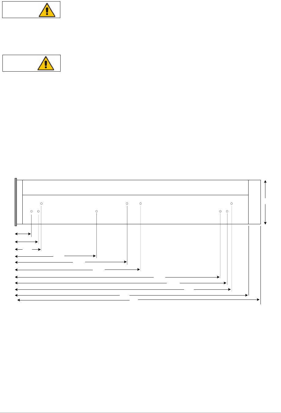
The MDR can be installed on telescopic slides, or on fixed runners, within a standard 483 mm (19 inch)
equipment rack. M4 tapped holes, each 10 mm deep (see Fig 7) are provided on each side of the
equipment to accept the slides. Details of suitable telescopic slides are available from Park Air.
When fitted in the rack, the MDR's front panel must be secured to the cabinet’s chassis using four
M6 x 16 mm screws and plastic washers.
Fig 1 Slide Fittings
Fig 7 Slide Fittings
WARNING Heavy Item
Caution Mechanical Support
Front
Panel
399
390.9
378.2
232.2
207.5
152.8
47.0
29.0
41.7
430
88.9
450
All measurements in mm
31-3MDR00HB Page 41 Installation
Draft
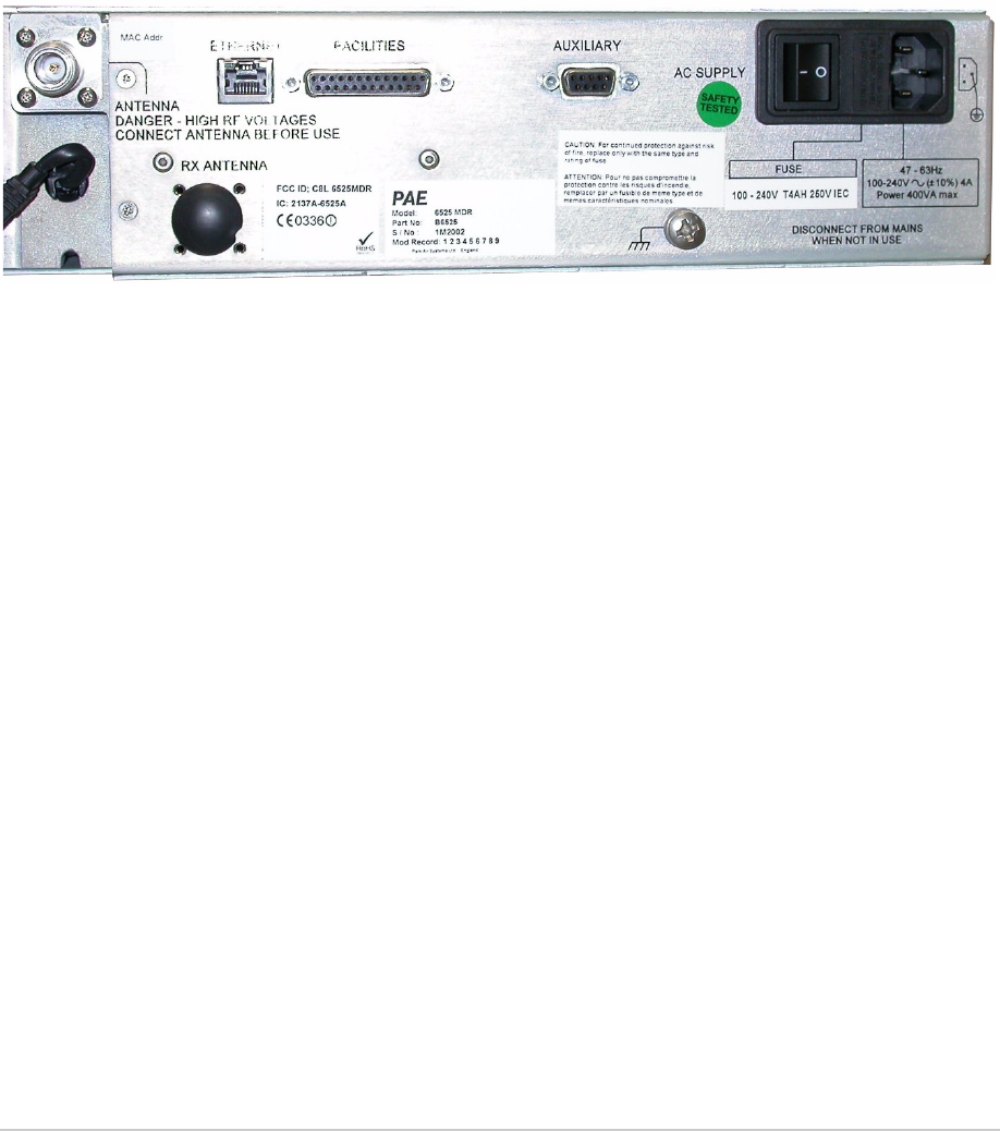
Rear Panel Interfaces
The rear panel Ethernet, Facilities and Auxiliary interfaces (Fig 8) are used to connect remote signals as
follows:
For AM-Voice The line, PTT and squelch inputs and outputs connect via the Facilities
interface.
For AM Analogue ACARS The analogue ACARS waveform connects between an external
modem and the line inputs and outputs via the Facilities interface.
For AM Digital ACARS The digital ACARS data connects via the Ethernet interface.
For VDL Mode 2 All control information and data to be transmitted and received is
transferred via the Facilities (HDLC connections) and Ethernet
interfaces.
Fig 8 Rear Panel Connectors
31-3MDR00HB Page 42 Installation
Draft
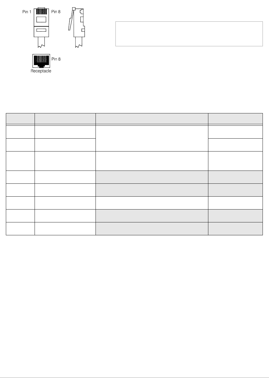
Ethernet Connector
The Ethernet RJ socket connects to a 10/100Base-T Ethernet network. The connector is shown in Fig 9
and the pin-out listed in Table 10.
Fig 9 Ethernet Connector Pin-out
Table 10 Ethernet Connector Pin-out
Pin Signal Name Characteristic Input or Output
1TD +
Balanced 100 ohm ±10%, 10/100 Mbps
Output
2 TD – Output
3RD +Balanced 100 ohm differs from the reference
by more than 10%, 10/100 Mbps Input
4 Not connected
5 Not connected
6 RD – Pair with pin 3 Input
7 Not connected
8 Not connected
Pin 1
Numbering is shown looking from the top of the connector.
The top is being viewed with the lever at the bottom.
RJ45 Plug
31-3MDR00HB Page 43 Installation
Draft
Facilities Connector
A 25-way D-type filtered socket providing analogue and HDLC interfaces. The connector is shown in
Fig 10 and the pin-out listed in Table 11. A suitable 25-way D-type plug to connect to this interface is
listed in Table 9 on page 39.
Fig 10 Facilities Connector Pin-out
Table 11 Facilities Connector
Pin Signal Name Characteristic Input or Output
1Ground 0 V.
2 Line in – Balanced 600 ohm, -20 to +10 dBm.
Phantom Keying:
Phantom PTT active when the input differs from the
reference by more than 10 V. Reference voltage
(common to PTT input on pin 25) is programmable to
+14, 0 or -14 V (all ±1 V).
Phantom PTT inactive when the input differs from the
reference by less than 1 V
Maximum input level ±60 V with respect to reference.
Input requires at least 1 mA to operate and draws no
more that 6 mA.
Configurable active high or low.
Input
3 Signal strength Between 0 and 5 V. Output
4Line out +Balanced 600 ohm, -20 to +10 dBm. Output
5Ground 0V.
6 HDLC 0 TX B RS422 differential synchronous data at 128 kbits per
second.
Output
7 HDLC 0 RX B RS422 differential synchronous data at 128 kbits per
second.
Input
8 HDLC 0 CL B RS422 differential synchronous data at 128 kbits per
second.
Output
9 HDLC 1 TX B RS422 differential synchronous data at 128 kbits per
second.
Output
10 HDLC 1 RX B RS422 differential synchronous data at 128 kbits per
second.
Input
continued ...
13 1
25 14

31-3MDR00HB Page 44 Installation
Draft
Note:
HDLC 0 is used for VDL Mode 2 operation.
HDLC 1 is reserved.
11 HDLC 1 CL B RS422 differential synchronous data at 128 kbits per
second.
Output
12 Squelch Solid state relay configurable to be normally open or
normally closed. Between +60 and -60 V ac or dc may be
applied drawing 100 mA maximum.
Output
13 Ground 0 V.
14 Line in +Pair to pin 2. Input
15 Ground 0 V.
16 Ground 0 V. –
17 Line out – Pair to pin 4. Output
18 HDLC 0 TX A Pair to pin 6. Output
19 HDLC 0 RX A Pair to pin 7. Input
20 HDLC 0 CL A Pair to pin 8. Output
21 HDLC 1 TX A Pair to pin 9. Output
22 HDLC 1 RX A Pair to pin 10. Input
23 HDLC 1 CL A Pair to pin 11. Output
24 Time 0 5 V CMOS Input
25 PTT Active when the input differs from the reference by more
than 10 V. Reference voltage (common to phantom PTT
input on pin 2) is programmable to be +14, 0 or -14 V (all
±1 V).
Inactive when the input differs from the reference by less
than 1 V
Maximum input level ±60 V with respect to reference.
Input requires at least 1 mA to operate and draws no
more that 6 mA.
Configurable active high or low.
Input
Table 11 Facilities Connector (Continued)
Pin Signal Name Characteristic Input or Output
31-3MDR00HB Page 45 Installation
Draft
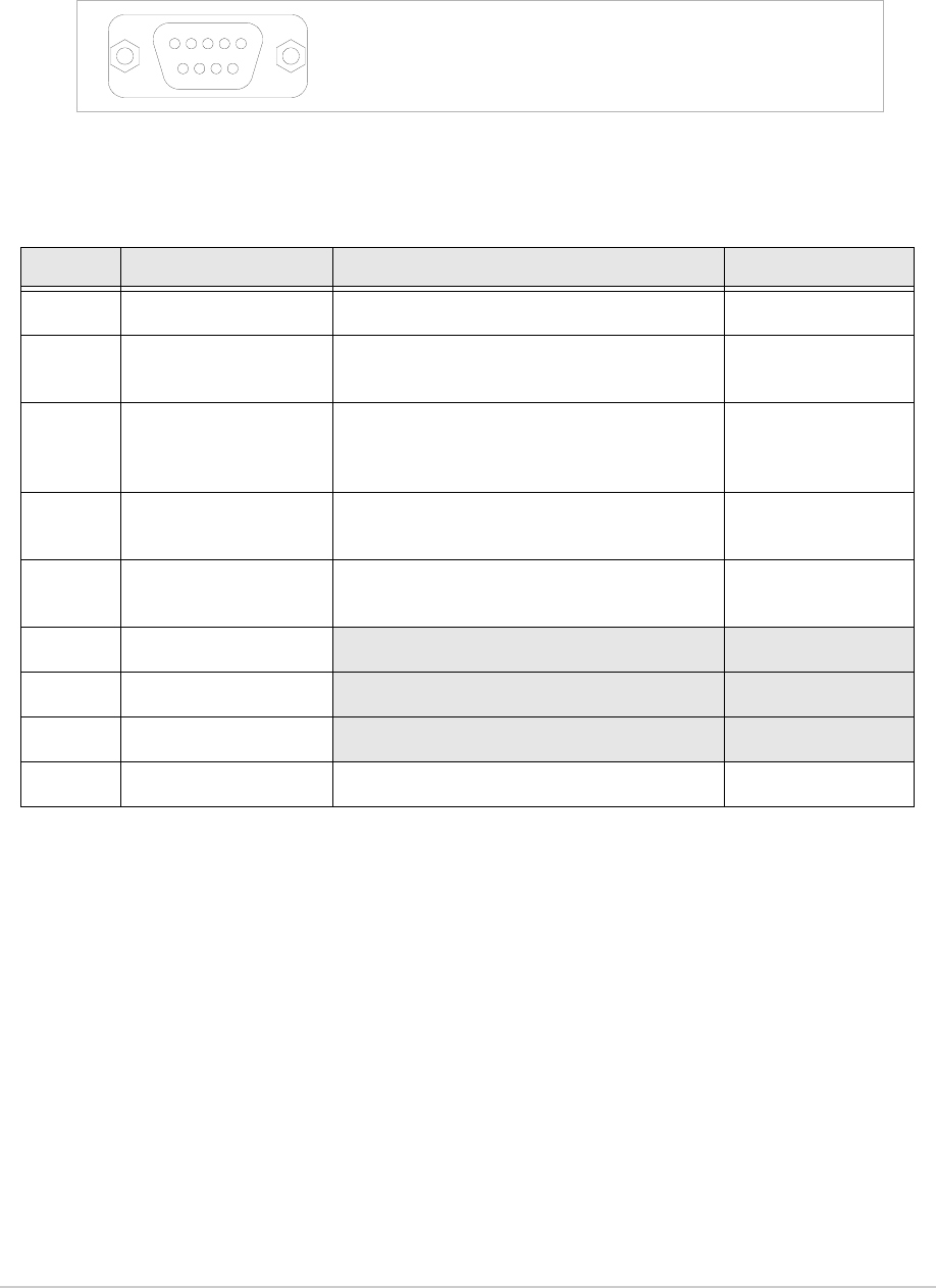
Auxiliary Connector
A 9-way D-type filtered socket for future interface expansion. The connector is shown in Fig 11 and the
pin-out listed in Table 12. A suitable 25-way D-type plug to connect to this interface is listed in Table 9
on page 39.
Fig 11 Auxiliary Connector Pin-out
Table 12 Auxiliary Connector Pin-out
Pin Signal Name Characteristic Input or Output
1Ground 0 V –
2 Antenna change-over Open collector NPN transistor grounding
output, normally open, 200 mA maximum. Output
3Reserved
Open collector NPN transistor grounding
output, configurable to be normally open or
normally closed, 200 mA maximum.
Output
4Reserved TTL with 4.7 kohm pull-up to 5 V.
Configurable to be active high or low. Input
5Reserved TTL with 4.7 kohm pull-up to 5 V.
Configurable to be active high or low. Input
6 Not connected
7 Not connected
8 Not connected
9 dc supply Between 21.6 and 32 Vdc. Fused at 500 mA. Output
Pin-out of Auxiliary connector looking into the mating face of
the chassis mounted socket.
A suitable free socket is detailed in Table 9 on page 39.
54321
9876
31-3MDR00HB Page 46 Installation
Draft
Connecting the Chassis Stud
A chassis stud is fitted to the MDR's rear panel. This stud is used to connect the equipment
to the equipment rack, or to the user's system earth point. The stud must not be used as the
safety earth.
In order not to compromise the MDR’s Electromagnetic Compatibility (EMC) the chassis stud, marked
and fitted to the rear panel must be connected to the equipment cabinet (if a cabinet is being used)
or to the user's system earth point. The connection should be made using a single tri-rated, green-and-
yellow cable having a cross-sectional area of 2.5 mm2. The cable should have CSA and UL1015
approval, and be connected to the chassis stud through an M6 eyelet (for example, Park Air part number
20-08010103).
Failure to comply with this instruction could result in non-compliance with the European
Commission EMC Directive 89/336/EEC.
Connecting an Antenna
The antenna used with the MDR must be installed such that the resultant radiated field
strength is below 10 W/m² in areas normally accessible to personnel.
The RF field strength from the antenna can be predicted from the equation S=1.4PG/4πR2
[Where S = power density; P = power input to antenna; G = antenna gain; R = distance
to centre of radiation and 1.4 = multiplication factor for average power based on a
modulation index of 90%.]
Based on this formula a 2 dBi antenna, the predicted safe distance from the centre of radiation would
be approximately 0.75 m for a field strength of 10 W/m2 (1 mW/cm2).
This meets the requirements of Health Canada Safety Code 6 for RF and microwave exposed
workers. For persons not classed as RF and microwave workers and including the general public
the limit is 2 W/m2 (0.2 mW/cm2) which increases the minimum safe distance to 1.7 m.
Further information on calculating the field strengths and power levels can be found in Health
Canada Safety Code 6 'Limits of Human Exposure to Radiofrequency Electromagnetic Fields in the
Frequency Range 3 kHz to 300 GHz', and also in FCC document OET Bulletin 65.
Ensure an antenna, or dummy load, is connected before switching on the MDR. There is high
RF voltage present at the antenna connector when the radio is keyed.
The MDR uses a common antenna for transmission and reception. The rear panel N-type (female)
antenna connector accepts a straight or right-angle N-type plug as listed in Table 9 on page 39. Park Air
recommends that RG214 1/2” flexible feeder cable, part number 10-05120610, be used for that part of
the feeder circuit that is within a building.
WARNING Chassis Earth
WARNING Antenna Radiation
WARNING Antenna Radiation
31-3MDR00HB Page 47 Installation
Draft
Checking the ac Input Fuse
For continued protection against risk of fire, replace only with the same type and rating of
fuse.
The ac input fuse is located in a pull-out holder that is an integral part of the ac connector. Check that the
fuse type is of the correct rating:
100 - 240V T4AH 250V IEC (Park Air part number, 29E01120108S)
AC Supply Connection
The equipment is permanently connected to the mains supply when the mains connector is
attached. Switching the rear panel Power switch to Off does not isolate all internal circuits
from the mains supply. For this reason, a mains isolating switch should be fitted close to,
and easily accessible from, the MDR's position. The isolation switch should isolate both live
and neutral supplies, be clearly labelled, and adequately rated to protect the equipment.
This equipment must be earthed. The earth terminal of the ac connector should be used as
the safety earth.
An ac input connector (see Fig 8 and Fig 12) is fitted to the equipment’s rear panel. The cable used to
connect between the equipment and the user’s ac power source should be 3-core (to IEC 227) rated
250 Vac at 8 amps, and have a minimum cross-sectional area of 1.0 mm2 per core. Park Air recommends
the use of polyvinyl chloride (PVC) insulated cable. The cable must be fitted with the IEC approved
equipment connector (Park Air part number 20-02030102) and conform to the following specification:
If PVC insulated, be not lighter than ordinary polyvinyl chloride sheathed flexible cord according
to IEC publication 227 (designation H05 VV-F, or H05 VVH2-F).
If rubber insulated, be of synthetic rubber and not lighter than ordinary tough rubber-sheathed
flexible cord according to IEC publication 245 titled ‘Rubber Insulated Cables of Rated Voltage up
to and Including 450/750 V (designation H05 RR-F)’.
Caution Fuse Rating
WARNING Dangerous Voltage
WARNING Earth Connection

31-3MDR00HB Page 48 Installation
Draft
The MDR is a Class 1 equipment. The ac supply cable should have a green-and-yellow protective
earthing conductor electrically connected to the protective earthing terminal of the equipment connector
and the mains plug. Park Air recommends the ac supply cable is colour coded in accordance with the
electrical appliance (colour code) regulations for the UK. That is:
The core coloured green-and-yellow must be connected to the terminal in the plug that is marked
with the letter E or by the earth symbol or coloured green-and-yellow.
The core coloured blue must be connected to the terminal that is marked with the letter N or
coloured black.
The core coloured brown must be connected to the terminal that is marked with the letter L or
coloured red.
Fig 12 ac Connector Pin-out
E
N
L
Draft
Maintenance

31-3MDR00HB Page 50 Maintenance
Draft
Maintenance Policy
Apart from the scheduled maintenance detailed in this topic, and replacing a faulty cooling fan, the
maintenance policy for the MDR is to return faulty units to Park Air.
Unscheduled Maintenance
Unscheduled maintenance is limited to replacing a faulty cooling fan (see page 54).
Scheduled Maintenance
Park Air recommends that scheduled maintenance be carried out at twelve-monthly intervals. Schedule
maintenance comprises:
(1) Ensuring the equipment is clean.
(2) Ensuring that the external connectors are securely fitted to the MDR.
(3) Checking and resetting (if required) the MDR's frequency standard (see page 51).
(4) Performing an interruptive BIT test (see page 52).
Cleaning the Equipment
Remove all dust and dirt from the equipment's exterior using cleaning cloths and a camel hair brush.
Clean the front panel indicators and LCD face.
Security of External Connections
Check all external connections are secure and free from damage.
There are no user serviceable parts within the MDR. Breaking the seals on the
top and bottom covers voids the MDR’s warranty.

31-3MDR00HB Page 51 Maintenance
Draft
Checking the MDR’s Internal Reference Frequency
To set the MDR’s internal reference frequency, use the following procedure. Note that references to the
switch in the procedure mean the Scroll/Select switch.
F r e q u e n c y
C h a n n e l
S e t t i n g s
E x i t > >
Control Screen
M o d e V D L M O D E 2
M o d e S e t t i n g s
P o l a r i t i e s
E X I T > >
Settings Screen (First Page)
B a n d E d g e s
I P S e t t i n g s
R e f F r e q 6 7 . 0 %
E x i t < < > >
Settings Screen (Second Page)
(1) If the MDR is used in AM-Voice mode
with a frequency offset, reset the offset
to 0 kHz.
(2) Connect a high impedance frequency
counter to the front panel Reference
connector.
(3) From the Main screen, press the switch
to display the Control screen. Turn the
switch until Settings is highlighted.
Press the switch.
(4) Ensure the Settings screen is displayed.
Turn the switch until Ref Freq is
highlighted, then press the switch.
(5) With Ref Freq selected turn the switch
clockwise or anti-clockwise until the
frequency counter reads 20.950000 MHz
±10 Hz, then press the switch.
(6) Turn the switch clockwise until Exit is
highlighted, then press the switch. You
are returned to the Main screen.
(7) Disconnect the frequency counter.

31-3MDR00HB Page 52 Maintenance
Draft
Initiating an Interruptive BIT Test
An interruptive BIT test is available only in AM-Voice and AM analogue ACARS modes.
Use the following procedure to initiate an interruptive BIT test from the MDR's front panel. A BIT test
cannot be initiated while the MDR is keyed.
During an interruptive BIT test, the MDR radiates modulated carrier waves at the set power.
Users should therefore obtain the necessary authority before initiating a test.
If the test is to be carried out with the antenna disconnected, ensure a load is fitted to the
MDR's Antenna connector.
In order to test the line input stages, an internally generated 1 kHz tone is injected into the
line input circuit. Any other audio present on the line input will cause the test to be
inaccurate. Therefore the MDR must not be keyed during the test.
F r e q u e n c y
C h a n n e l
S e t t i n g s
E x i t > >
Control Screen (Page 1)
B I T
S / W C o n f i g
E x i t < <
Control Screen (Page 2)
B I T I n i t i a t e
E T I 0 0 0 1 0 1 : 3 6 h r s
S u p p l y 2 5 v
E x i t > >
BIT Screen
(1) From the Main screen, press the switch
to display the Control screen. Turn the
switch until BIT is highlighted. Press the
switch.
(2) Ensure the BIT screen is displayed.
Turn the switch until BIT Initiate is
highlighted. Press the switch.
(continued)

31-3MDR00HB Page 53 Maintenance
Draft
T e s t i n g
P l e a s e W a i t
T e s t S t a t u s
P A S S
O K
T e s t S t a t u s
F A I L
O K
(3) During the test, which takes
approximately two seconds, the
Testing screen is displayed.
(4) When the test is complete, either Pass
or Fail is displayed.

31-3MDR00HB Page 54 Maintenance
Draft
Removing and Refitting the Cooling Fan
The cooling fan is at the rear of the MDR as shown in Fig 13.
The part number of the fan is: 69J1208314H
Fig 13 Cooling Fan Removal
Removal
Before attempting to remove the fan, ensure that the MDR is isolated from the ac input supply. Then
proceed as follows:
(1) Disconnect the two-pin power connector.
(2) Remove the fan's finger guard.
(3) Using an Allen key, inserted through the holes in the fan exposed with the finger guard removed,
remove the four M4 x 12 mm caphead Allen screws that secure the fan to the PA module
heatsink.
(4) Remove the fan from the PA module.
Refitting
To refit the cooling fan, proceed as follows:
(1) Locate the fan in position and using a suitable Allen key inserted through the holes for the fan's
finger guard, secure using the four M4 x 12 mm caphead Allen screws.
(2) Secure the finger guard to the fan.
(3) Connect the 2-pin fan connector to the fan. Ensure the + marked socket mates with the + marked
plug on the fan.
(4) Re-establish the ac supply.
(5) Switch power on at the MDR using the rear mounted Power switch.
(6) Ensure the front panel Ready indicator is lit and the Alarm indicator is unlit.
Power
Connector
Finger
Guard