Park Air Systems B63300HS VHF Ground to Air Transmitter User Manual 300W VHF Hardcopy
Park Air Systems Limited VHF Ground to Air Transmitter 300W VHF Hardcopy
UserManual.wiki
>
Park Air Systems
>
B63300HS User Manual
>
user manual part 2
Contents
1.
user manual part 1
2.
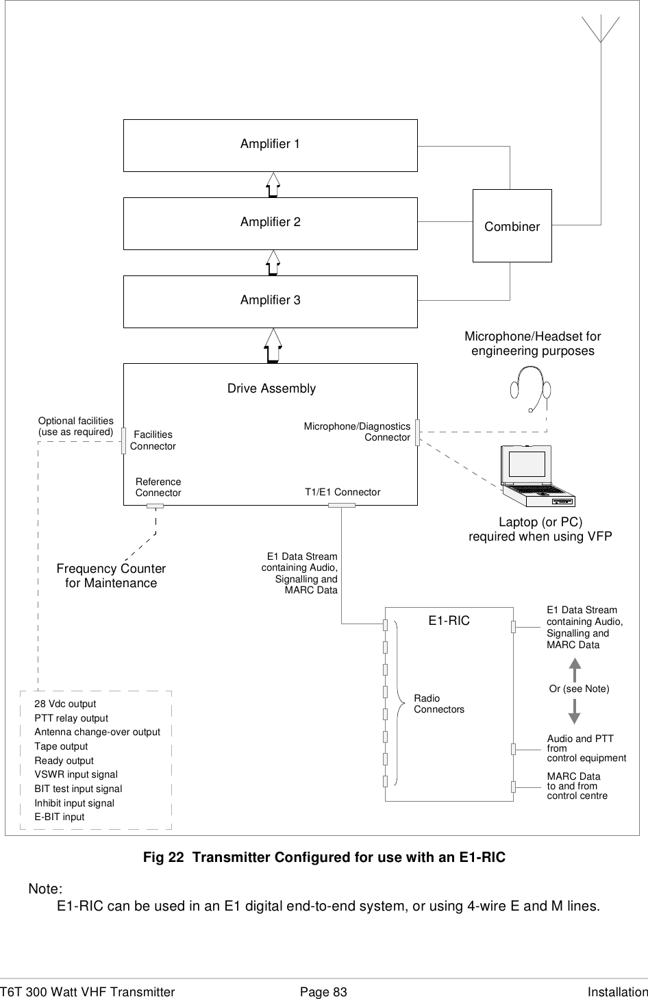
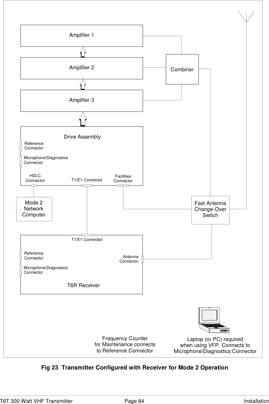
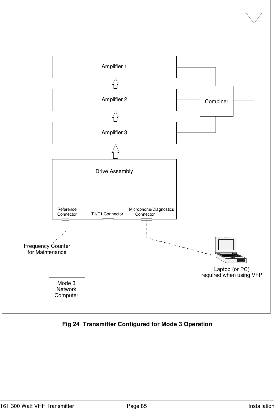
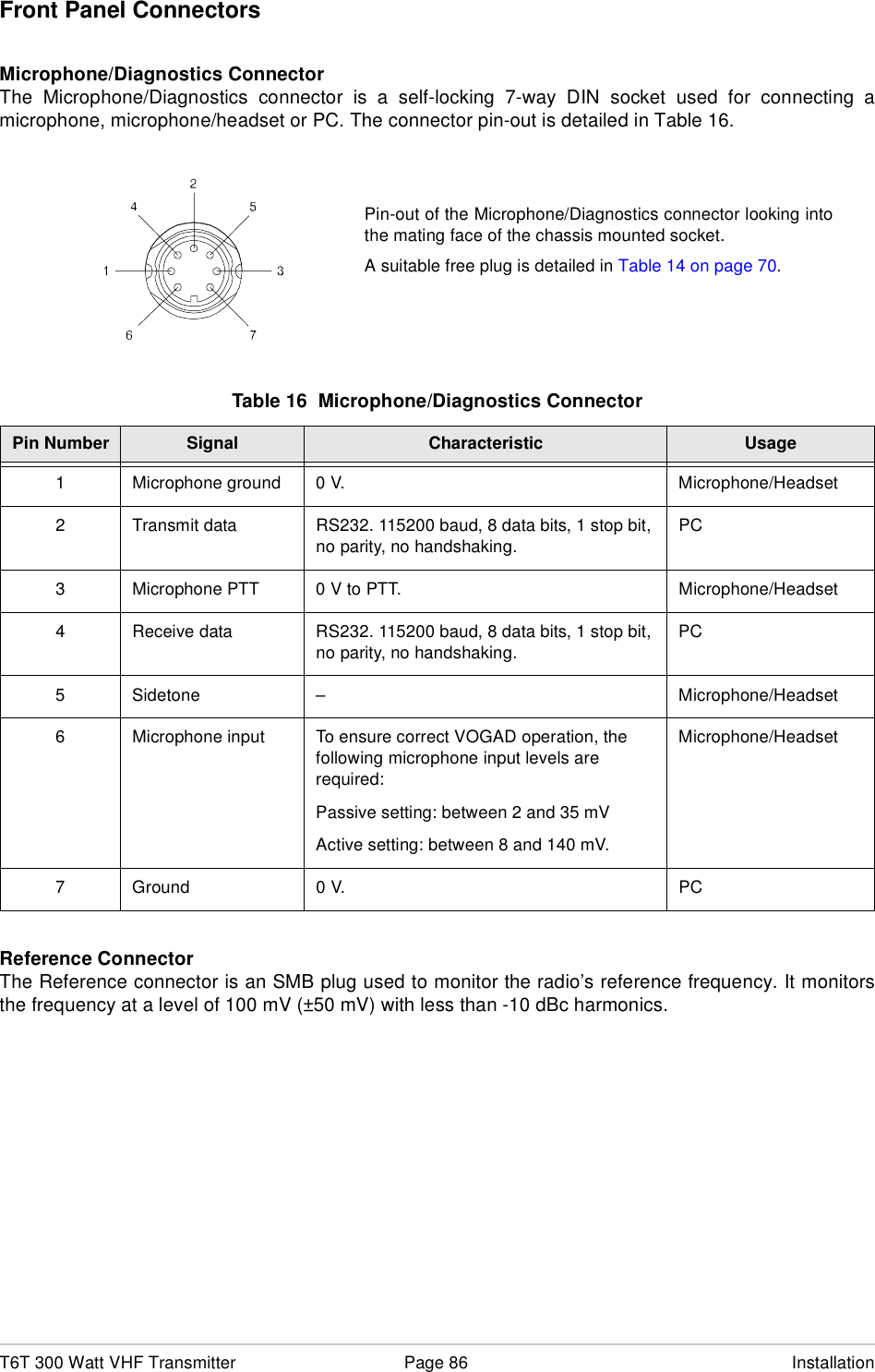
user manual part 2
user manual part 2
Navigation menu
Upload a User Manual
Namespaces
Wiki Guide
HTML
PDF
Info
Views
User Manual
Discussion / Help
Navigation