Park Air Systems B63300HS VHF Ground to Air Transmitter User Manual 300W VHF Hardcopy
Park Air Systems Limited VHF Ground to Air Transmitter 300W VHF Hardcopy
Contents
- 1. user manual part 1
- 2. user manual part 2
user manual part 1

T6T 300 Watt VHF Transmitter
User Documentation

Page 2
Handbook Title: T6T 300 Watt VHF Transmitter User Documentation
Handbook Part Number: 31-3T6T300V
Handbook Version: 1.1
Date of Issue: June 2006
Published By: Park Air Systems
Northfields
Market Deeping
Peterborough
PE6 8UE
England
Telephone: From UK, 01778 345434
From outside UK, 44 1778 345434
Fax: From UK, 01778 342877
From outside UK, 44 1778 342877
www.parkairsystems.com
Errata
Any errors found in this handbook, or associated equipment handbooks, are promulgated
through the Park Air FTP network. Any user can access this information by logging on to:
ftp.parkairsystems.com
When logged on, select the public (Pub) folder, then the Handbook Errata Sheets folder,
and then select the required equipment model.
[Adobe Acrobat™ must be loaded on your PC to use this facility.]
US
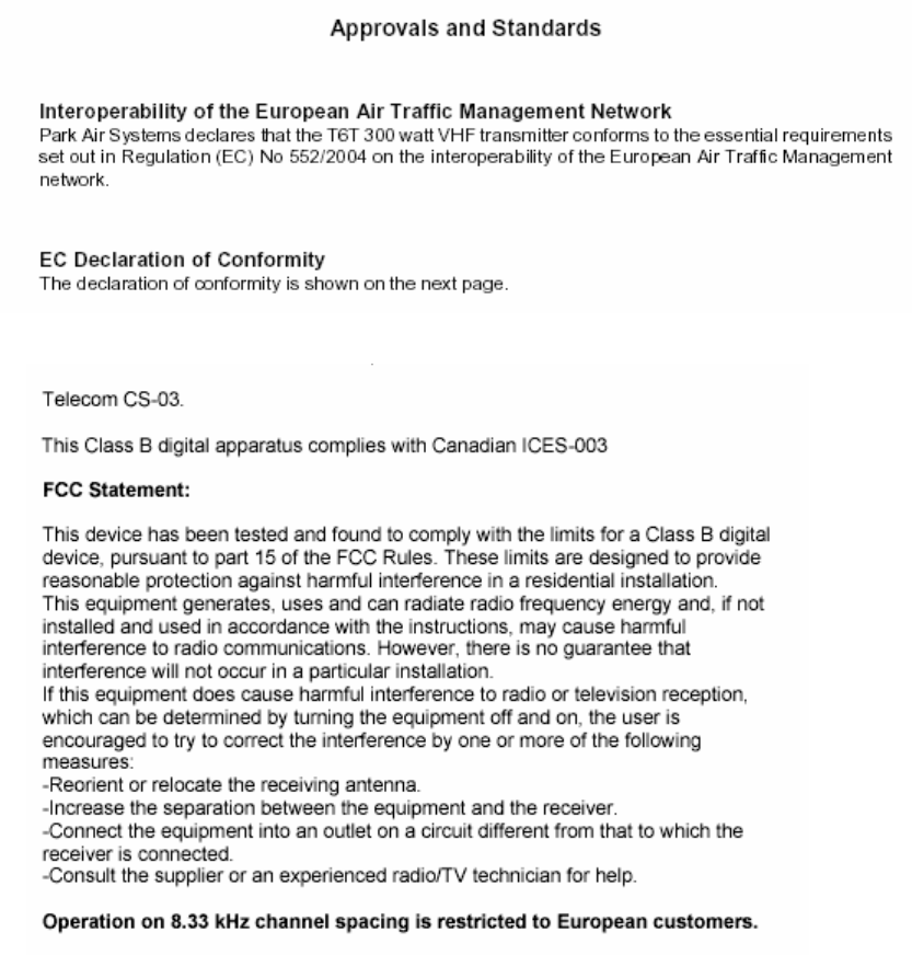
Health & Safety, EN 60950, CAN/CSA-C22.2 No. 60950, UL 60950.
Radio IC RSS141, FCC part 15 and 87.
Operation at greater than 200W is subject to FAA approval
Page 4
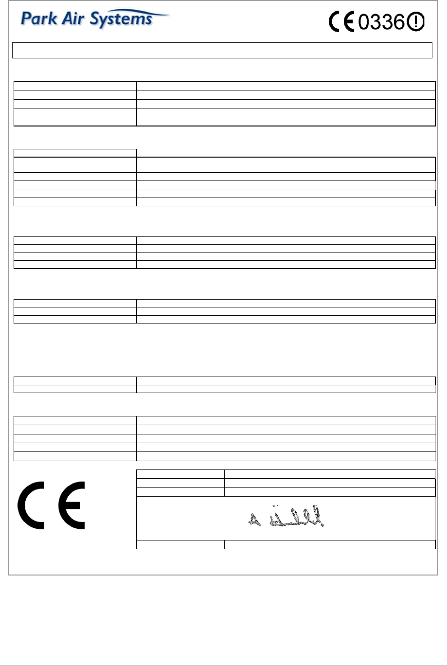
Declaration of Conformity
We, the undersigned,
Company Park Air Systems Limited
Address, City Northfields, Market Deeping, Peterborough PE6 8UE
Country England
Phone number +44 1778 345434
Fax number +44 1778 342877
certify and declare under our sole responsibility that the following equipment:
Product description / Intended use Ground to air communications in the VHF aeronautical band
EU / EFTA member states intended
for use All countries
Member states with restrictive use None
Manufacturer Park Air Systems Limited
Brand PAE
Type T6T HS 300 , T6T HS 200
are tested to and conform with the essential requirements for protection of health and the safety of the user and any other person and
Electromagnetic Compatibility, as included in following standards:
Standard Issue date
EN60950-1:2002 2002
EN60215 1989
EN301 489-1, EN301 489-22 06/2005, 11/2003
and is tested to and conforms with the essential radio test suites so that it effectively uses the frequency spectrum allocated to terrestrial/space
radio communication and orbital resources so to as to avoid harmful interference, as included in following standards:
Standard Issue date
EN 300 676 V1.3.1 03/2003
and therefore complies with the essential requirements and provisions of the Directive 1999/5/EC of the European Parliament and of the
council of March 9, 1999 on Radio equipment and Telecommunications Terminal Equipment and the mutual recognition of their conformity and
with the provisions of Appendix IV (Conformity Assessment procedure referred to in article 10).
The following Notified Body has been consulted in the Conformity Assessment procedure:
Notified Body number Name and address
0336 TNO Certification B.V., PO Box 15, 9822 ZG Niekerk, The Netherlands
The technical documentation as required by the Conformity Assessment procedure is kept at the following address:
Company Park Air Systems Limited
Address, City Northfields, Market Deeping, Peterborough PE6 8UE
Country England
Phone number +44 1778 345434
Fax number +44 1778 342877
TCF/TF reference nr. TCF-124-008
Drawn up in Northfields, Market Deeping, Peterborough PE6 8UE
Date 10 October 2005
Name and position A. Horsfield consultant Engineer
Page 5
Health and Safety
T6T 300 Watt VHF Transmitter
The T6T 300 watt VHF transmitter operates from a low voltage dc input supply, or a standard mains ac
input supply. When using a mains supply, dangerous voltages are present on the rear panel ac connector
and within the equipment. For this reason, only suitably qualified personnel should install and maintain
the equipment.
In use, an antenna is connected to the transmitter. During installation, consideration must be
given regarding the resultant field strength in areas accessible to personnel. The formula to
determine the field strength is given in the Installation topic.
The output transistors used in the power amplifier (PA) of this transmitter contain the toxic
material beryllium. Beryllium oxide dust is toxic if inhaled.
Although no procedures in this documentation instruct component removal, users should be
aware that there could be a hazard if a PA’s output transistors become physically damaged.
The transmitter weighs approximately 79 kg. When lifting a transmitter, especially when
fitting into an equipment cabinet, a minimum of two people should be used. Failure to do so
can result in personal injury.
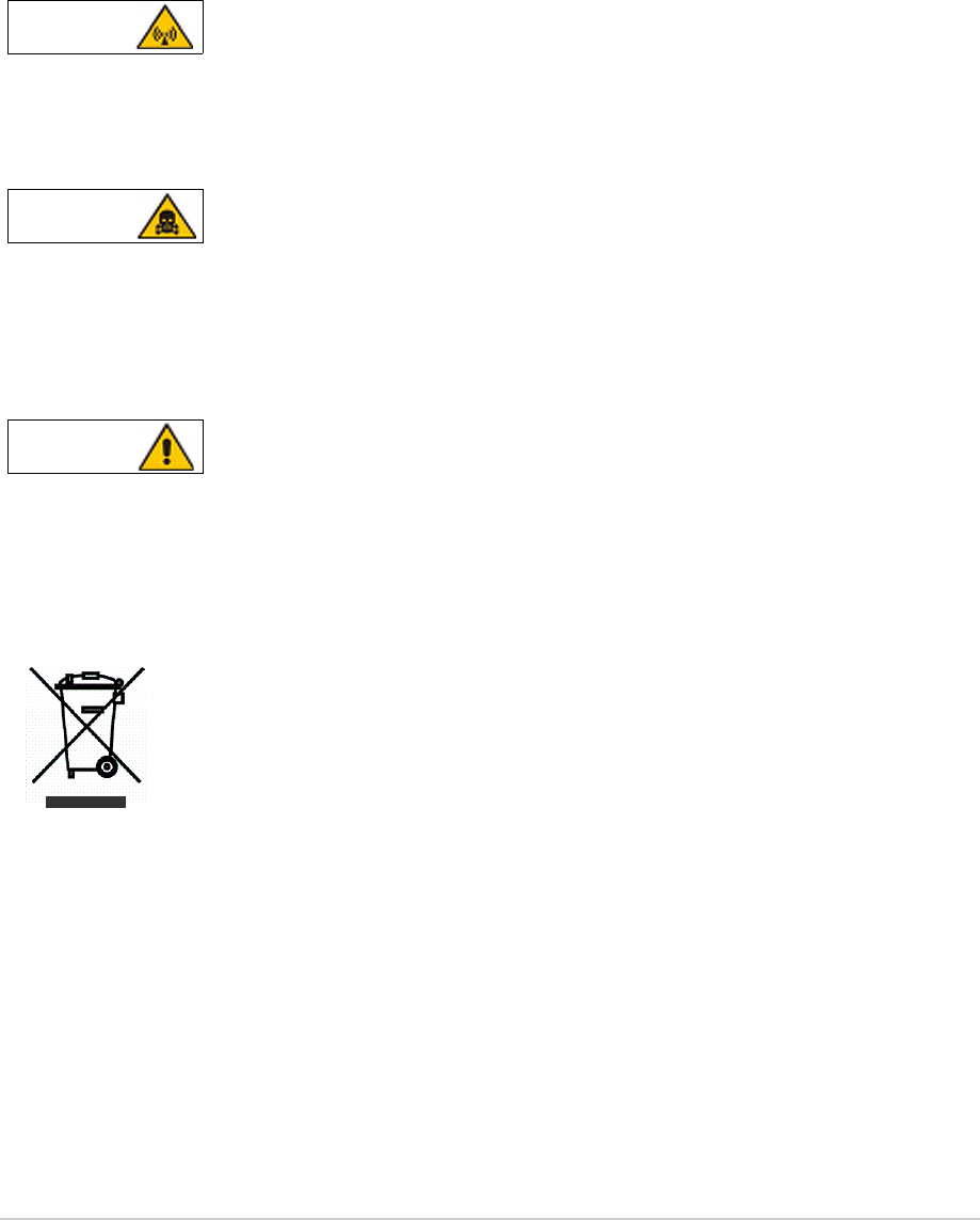
Disposal This product is covered by the European Directive 2002/96/EC.
It must not be disposed of in domestic waste.
Disposal should be made using designated collection facilities appointed by the
government or the local authorities in your area.
Antenna Radiation WARNING
Beryllium Hazard WARNING
Lifting the Transmitter WARNING
Page 6
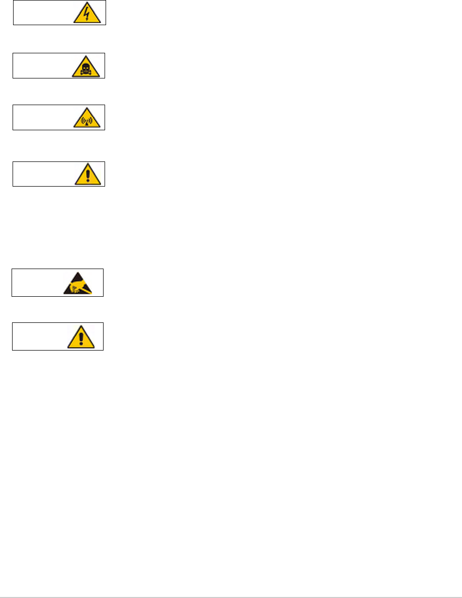
Warnings and Cautions
The following warnings and cautions are used in Park Air documentation.
Warnings
A warning is used to indicate possible danger to personnel. Throughout Park Air user documentation,
warnings are indicated by the following symbols:
Cautions
A caution is used to indicate possible danger to the equipment. Throughout Park Air user documentation,
cautions are indicated by the following symbols:
Indicates electrical danger to personnel.WARNING
Indicates a hazardous material.WARNING
Indicates a non-ionizing radiation hazard. WARNING
Indicates a specified danger to personnel. WARNING
Indicates the presence of electrostatic sensitive devices (ESDs). Caution
Indicates a specified danger to the equipment. Caution

Page 7
Customer Support
Contacting Park Air
Customer support is available using email, telephone or fax. If you require help in configuring, installing
or maintaining equipment supplied by Park Air, use any of the contact methods listed below.
Email
Address: support@uk.parkairsystems.com
Telephone
During normal UK office hours: +44 1778 381557
Outside normal UK office hours: +44 7733 124457
Fax
Fax number: +44 1778 381556
Mail
Address: Customer Services Department
Park Air Systems
Northfields
Market Deeping
Peterborough PE6 8UE
England
Web Site
Web address: www.parkairsystems.com
Fault Reporting
To ensure that Park Air continues to offer the highest level of after sales service, it is necessary to gather
as much information as possible about equipment faults. If any equipment supplied by Park Air becomes
unserviceable, please complete a copy of the fault report shown on the next page, and return it to the
Customer Services department at Park Air.

Page 8
Fault Report
Customer: . . . . . . . . . . . . . . . . . . . . . . . . . . . . . . . . . . . . . . . . . . . . . . . . . . . . . . . . . . . . . . . . . . . .
Address: . . . . . . . . . . . . . . . . . . . . . . . . . . . . . . . . . . . . . . . . . . . . . . . . . . . . . . . . . . . . . . . . . . . .
. . . . . . . . . . . . . . . . . . . . . . . . . . . . . . . . . . . . . . . . . . . . . . . . . . . . . . . . . . . . . . . . . . . .
. . . . . . . . . . . . . . . . . . . . . . . . . . . . . . . . . . . . . . . . . . . . . . . . . . . . . . . . . . . . . . . . . . . .
Telephone: . . . . . . . . . . . . . . . . . . . . . . . . . . . . . . . . . . . . . . . . . . . . . . . . . . . . . . . . . . . . . . . . . . . .
Email: . . . . . . . . . . . . . . . . . . . . . . . . . . . . . . . . . . . . . . . . . . . . . . . . . . . . . . . . . . . . . . . . . . . .
Fax: . . . . . . . . . . . . . . . . . . . . . . . . . . . . . . . . . . . . . . . . . . . . . . . . . . . . . . . . . . . . . . . . . . . .
Equipment Details
Park Air works order number . . . . . . . . . . . . . . . . . . . . . . . . . . . . . . . . . . . . . . . . . . . . . . . . . . . . . . . . . .
Equipment model . . . . . . . . . . . . . . . . . . . . . . . . . . . . . . . . . . . . . . . . . . . . . . . . . . . . . . . . . . . . . . . . . . .
Equipment serial number . . . . . . . . . . . . . . . . . . . . . . . . . . . . . . . . . . . . . . . . . . . . . . . . . . . . . . . . . . . . .
Service Details
Commissioning date. . . . . . . . . . . . . . . . . . . . . . . . . . . . . . . . . . . . . . . . . . . . . . . . . . . . . . . . . . . . . . . . .
Failure/repair date . . . . . . . . . . . . . . . . . . . . . . . . . . . . . . . . . . . . . . . . . . . . . . . . . . . . . . . . . . . . . . . . . .
Software version (if known) . . . . . . . . . . . . . . . . . . . . . . . . . . . . . . . . . . . . . . . . . . . . . . . . . . . . . . . . . . .
Supply voltage . . . . . . . . . . . . . . . . . . . . . . . . . . . . . . . . . . . . . . . . . . . . . . . . . . . . . . . . . . . . . . . . . . . .
Equipment environment: Office area / dedicated equipment room / heated / air-conditioned
(delete as applicable)
Fault Detail
Symptoms of fault: . . . . . . . . . . . . . . . . . . . . . . . . . . . . . . . . . . . . . . . . . . . . . . . . . . . . . . . . . .
. . . . . . . . . . . . . . . . . . . . . . . . . . . . . . . . . . . . . . . . . . . . . . . . . . . . . . . . . .
. . . . . . . . . . . . . . . . . . . . . . . . . . . . . . . . . . . . . . . . . . . . . . . . . . . . . . . . . .
. . . . . . . . . . . . . . . . . . . . . . . . . . . . . . . . . . . . . . . . . . . . . . . . . . . . . . . . . .
Results of any tests: . . . . . . . . . . . . . . . . . . . . . . . . . . . . . . . . . . . . . . . . . . . . . . . . . . . . . . . . . .
. . . . . . . . . . . . . . . . . . . . . . . . . . . . . . . . . . . . . . . . . . . . . . . . . . . . . . . . . .
Any repairs carried out: . . . . . . . . . . . . . . . . . . . . . . . . . . . . . . . . . . . . . . . . . . . . . . . . . . . . . . . . . .
. . . . . . . . . . . . . . . . . . . . . . . . . . . . . . . . . . . . . . . . . . . . . . . . . . . . . . . . . .
Comments/action requested: . . . . . . . . . . . . . . . . . . . . . . . . . . . . . . . . . . . . . . . . . . . . . . . . . . . . . . . . . .
. . . . . . . . . . . . . . . . . . . . . . . . . . . . . . . . . . . . . . . . . . . . . . . . . . . . . . . . . .

Page 9
Abbreviations
The following list gives the standard abbreviations used in Park Air user documentation.
Aampere
ac alternating current
AGC automatic gain control
AM amplitude modulation
ATC air traffic control
BER bit error rate
BIT built-in test
C celsius
CAS channel associated signalling
CCE control centre equipment
CD compact disk
CSMA carrier sense multiple access
dB decibel
dBm decibels relative to 1 mW
dc direct current
DSB double sideband
D8PSK differentially encoded 8-phase shift
keying
E1-RIC E1-radio interconnect
E-BIT external bit signal
EMF electromagnetic force
ESD electrostatic sensitive device
ETSI European Telecommunications
Standards Institute
Fig figure
FM frequency modulation
ggramme
HPA high power amplifier
Hz hertz
ICAO international civil aviation
organization
IF intermediate frequency
kbits/s kilobits per second
kg kilogramme
kHz kilohertz
LCD liquid crystal display
LED light emitting diode
LRU line replaceable unit
mmetre
mA milliamp
MARC multi-access remote control
Mbits/s megabits per second
MHz megahertz
mm millimetre
ms millisecond
MSK minimum shift keying
mV millivolt
mW milliwatt
PA power amplifier
PC personal computer
PCB printed circuit board
PCU protocol conversion unit
pk-pk peak-to-peak
ppm parts per million
PSU power supply unit
PTT press to transmit
PVC polyvinyl chloride
RCMS remote control and monitoring
system
RF radio frequency
RSE2 remote site equipment
RSSI radio signal strength indication
SINAD signal plus noise plus distortion to
noise plus distortion ratio
S+N/N signal plus noise to noise ratio
TDMA time division multiple access
TS time slot
UHF ultra high frequency
µW microwatt
Vvolt
VA volt-ampere

Page 10
VCCS voice control and communication
switch
VFP virtual front panel
VHF very high frequency
VOGAD voice-operated gain adjusting device
Wwatt

Table of Contents
Page
Page 11
Approvals and Standards 3
Health and Safety 5
Customer Support 7
Abbreviations 9
Overview 15
Purpose 16
Models and Part Numbers 18
Mechanical Installation 18
Operating Parameters 19
Frequency Selection 19
Virtual Front Panel 19
Specification 21
General Specification 22
Variants 22
Number of Channels 22
Frequency Accuracy 22
Power Requirements 22
Dimensions and Weight 23
Transmitter 23
Combiner 23
Environmental 23
AM Modes 24
Transmitter RF Characteristics 24
Output Impedance 24
RF Power Output 24
Duty Cycle 24
Channel Spacing 24
Offset Carrier 24
Harmonic Outputs 24
Spurious Outputs 25
Intermodulation 25
Transmitter Modulation Characteristics 25
Mode 25
Modulation Depth 25
Hum and Noise 25
Frequency Response 25
Distortion 25
Residual FM 26
VOGAD 26
Mute 26
Differential Group Delay 26
Transmitter Control 26
Audio Inputs 26
PTT Time Out 26

Page 12
Table of Contents (continued)
Page
Mode 2 27
RF Power Rise Time 27
RF Power Decay Time 27
Channel Spacing 27
Transmitter Modulation Characteristics 27
Modulation Rate 27
RMS Phase Error 27
Phase Acceleration 27
Transmitter Control 27
Time Out 27
Mode 3 28
RF Power Rise Time 28
RF Power Decay Time 28
Channel Spacing 28
Transmitter Modulation Characteristics 28
Modulation Rate 28
RMS Phase Error 28
Phase Acceleration 28
Transmitter Control 28
Operation 29
Overview 30
T6T VHF Amplifier 31
Rear Panel Supply Switch 32
Drive Assembly 33
Front Panel Controls and Indicators 34
Scroll/Select Switch and LCD 34
Ready Indicator 34
Transmit Indicator 34
Alarm Indicator 34
Standby Indicator 35
Reference Connector 35
Microphone/Diagnostics Connector 35
Rear Panel Supply Switch 36
Setting Up and Operation 37
Normal Operation 37
Using the Scroll/Select Switch 37
Screen Protocol 38
Menu System 38
Menu Lock Screen 40
Control Screen 40
Notes for Setting Up the Transmitter 41
Front Panel Display for 25 kHz and 8.33 kHz Channel Spacing 41
Line Level Setting 42
Offset Carrier Operation 42
Changing the Transmitter’s Operating Frequency 43
To Store and Recall Frequency Channels 44
To Store a Channel Frequency: 44
To Recall a Stored Frequency Channel: 44
To Initiate a BIT Test 45
Standby Mode 46
To Enter Standby Mode 46
To Exit Standby Mode 46
Settings 47
AM-Voice Settings Procedure 49
AM-Voice Mode Settings Screen 49

Page 13
Table of Contents (continued)
Page
AM-MSK Mode Settings Procedure 51
AM-MSK Mode Settings Screen 51
Mode 2 Settings Screen 52
Mode 3 Settings Screen 52
Polarities Screen AM-Voice and AM-MSK 53
AM-Voice and AM-MSK Polarity Settings 53
Mode 2 and Mode 3 Polarity Settings 56
AM-Voice and AM-MSK BIT Screen 57
Mode 2 and Mode 3 BIT Screen 59
Software Configuration Screens 60
Band Edges 61
BIT Status Warning Screens 62
Installation 67
Warnings and Cautions 68
Introduction 69
Fuses and Connectors 70
Installing the Transmitter 71
Initial Inspection of the Transmitter 71
Fitting the Correct ac Input Fuses 71
Fitting the Drive Assembly and Amplifiers into an Equipment Cabinet 72
Connecting the Amplifiers to the Drive Assembly 73
Fitting and Connecting the Combiner 74
Fitting 74
Connecting 75
Connecting the Antenna 75
Connecting the Chassis Stud 77
Connecting the DC Input Supply 77
Connecting the AC Input Supply 78
Configuring the Transmitter for Operational Use 79
Front Panel Connectors 86
Microphone/Diagnostics Connector 86
Reference Connector 86
Rear Panel Connectors 87
MARC Connector 88
MARC Audio Connector 89
MARC Data Connector 91
T1/E1 Connector 92
HDLC Connector 93
External Speaker 94
Facilities Connector 95

Page 14
Table of Contents (continued)
Page
Maintenance 97
Introduction 98
Configuration 98
Hardware Configuration 98
Software Configuration 99
Replacement Modules 99
Scheduled Maintenance 100
Cleaning and Checking Security of Connectors 100
Setting the Transmitter Internal Reference Frequency 100
Setting a 5-Offset Carrier Frequency 101
To Initiate a BIT Test 102
AC and DC Change-over Check 103
Unscheduled Maintenance 104
Introduction 105
Molex KK Connectors 105
Tools, Materials and Test Equipment Required 105
T6T VHF Amplifier Procedures 106
Top and Bottom Covers 106
Removing and Refitting the Interface Module 106
Removing and Refitting the PSU Regulation Module 108
Removing and Refitting the Power Supply Modules 109
Removing and Refitting the Combiner BIT Module 110
Removing and Refitting the PA Modules 112
Removing and Refitting the Front Panel PCB 114
Removing and Refitting the Cooling Fans 115
T6T VHF Drive Assembly Procedures 116
Removing the Top Cover 116
Removing and Refitting the Processor Module 116
Removing and Refitting the PSU Regulation Module 118
Removing and Refitting the Drive Module 120
Removing the Bottom Cover 121
Removing and Refitting the PA Control Module 121
Removing and Refitting the Power Supply 123
Removing and Refitting the Front Panel PCB 124
Virtual Front Panel (VFP) 126
Installing the VFP Software 127
VFP Features 127
The Menu Bar 127
Settings Window 128
Channels Window 128
BIT Window 128
Status Information Window 128
To Change the Drive Assembly Profile or Save a Profile 129
To Initiate a BIT Test 130
To Calibrate the Transmitter 130
Overview
T6T 300 Watt VHF Transmitter Page 16 Overview
Purpose
The T6T 300 watt VHF transmitter is intended for use in fixed ground environments such as airports and
en-route centres. The transmitter operates in voice and ICAO defined data modes at frequencies
between 118 and 136.975 MHz. Dependent on the software loaded into the radio, the following operating
modes can be selected:
❑AM-Voice. All transmitters have this mode
❑AM-MSK (optional)
❑Mode 2 (optional)
❑Mode 3 (optional).
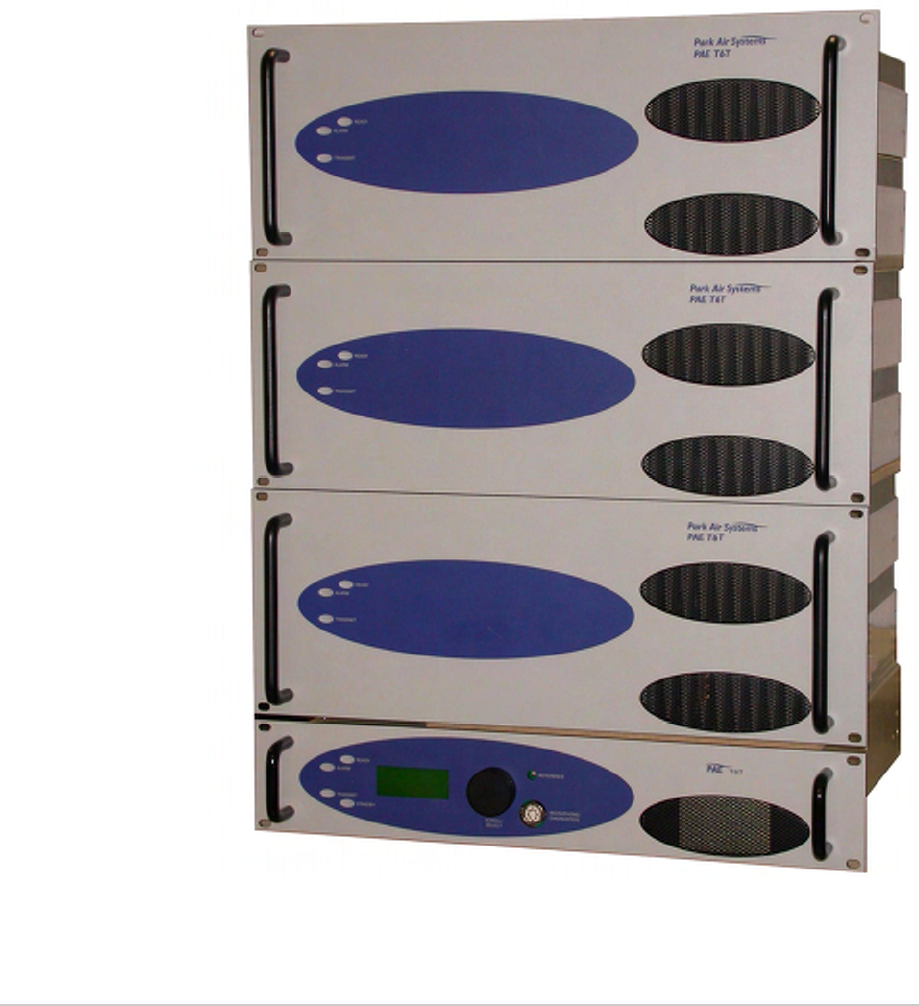
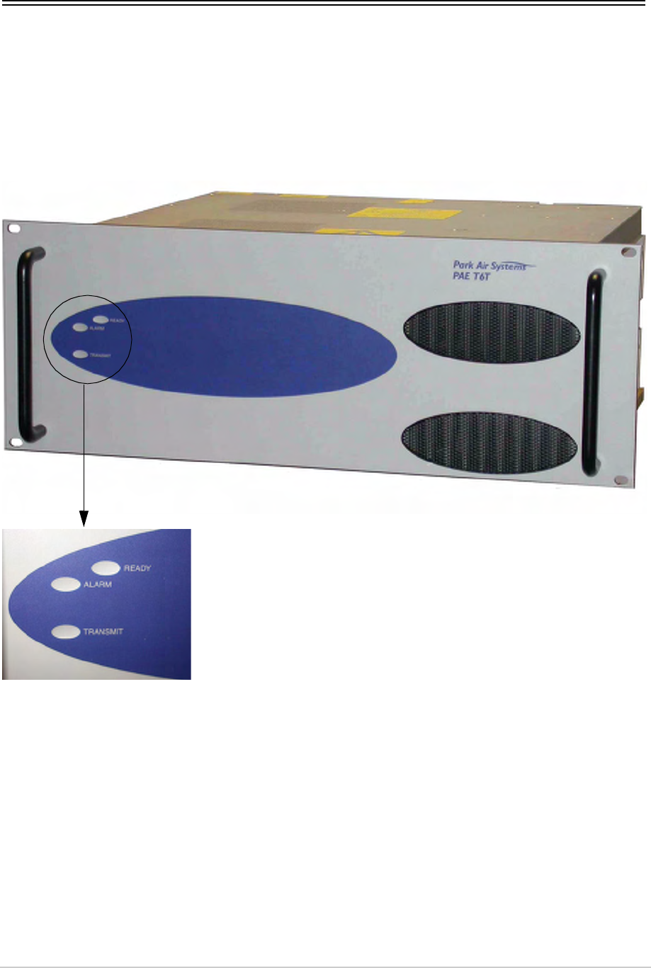
The transmitter, see Fig 1 and Fig 2, consists of a drive assembly, three 100 watt amplifiers and a
combiner. The transmitter is configured as shown in Fig 3. Should any one of the amplifiers fail, the
transmitter continues to operate at reduced (200 watt) power.
Fig 1 T6T 300 Watt VHF Transmitter
T6T VHF Amplifier
T6T VHF Amplifier
T6T VHF Amplifier
T6T VHF Drive Assembly
T6T 300 Watt VHF Transmitter Page 17 Overview
Fig 2 T6T VHF Combiner
Fig 3 300 Watt Transmitter Arrangement
Drive Assembly
100 W Amplifier
100 W Amplifier
100 W Amplifier
Combiner
T6T 300 Watt VHF Transmitter Page 18 Overview
Models and Part Numbers
Table 1 identifies a T6T 300 watt VHF transmitter.
Fig 4 shows the identification labels attached to each component. Each label identifies the model, part
number, serial number and modification level.
Fig 4 Identification Label Examples
Mechanical Installation
The transmitter, as shown in Fig 1, fits into an industrial standard 19 inch (483 mm) equipment cabinet
and occupies, in total, 14U of cabinet space. Additionally, the combiner must be mounted at the back of
the equipment cabinet directly behind the amplifiers’ cooling fans. A bracket provided (shown fitted in
Fig 2) is used to mount the combiner on a cabinet upright.
Table 1 Model Identification
Description Part Number Frequency Range Channel
Spacing
(AM-Voice)
Special
Applications
T6T 300 watt standard frequency
coverage, high stability, VHF
transmitter
B63300HS 118 to 136.975 MHz 25 kHz or
8.33 kHz
Supports 5-offset
carrier operation
Model:
Part No:
S / No:
Mod Record:
T6T VHF Drive Assembly
24-06633001/3
2L0001
X 6 7 8 9 10 11 12 13
Park Air Systems Ltd England
PAE Model:
Part No:
S / No:
Mod Record:
T6T VHF Amplifier
24-31633001/2
2L0001
X 6 7 8 9 10 11 12 13
Park Air Systems Ltd England
PAE Model:
Part No:
S / No:
Mod Record:
T6T VHF Combiner
24-33633001/2
2L0001
1 2 3 4 5 6 7 8 9 10
Park Air Systems Ltd England
PAE
Drive Assembly Identification Label Amplifier Identification Label Combiner Identification Label
T6T 300 Watt VHF Transmitter Page 19 Overview
Operating Parameters
The transmitter’s operating parameters are set using the drive assembly’s multi-purpose Scroll/Select
switch, or remotely from suitable control equipment. Additionally, the Park Air Virtual Front Panel (VFP)
software can be used to set up the transmitter.
Frequency Selection
The transmitter is a single frequency synthesised radio that can operate with 25 kHz and 8.33 kHz
channel spacing. The radio recognizes frequencies entered in ICAO format and automatically adjusts to
the correct channel spacing. For multichannel operation up to 100 preset frequency channels can be
stored in the radio for immediate recall; any combination of 8.33 kHz and 25 kHz channel spacing can
be stored. Valid operating frequencies can be selected from the radio’s front panel or a compatible
remote control equipment.
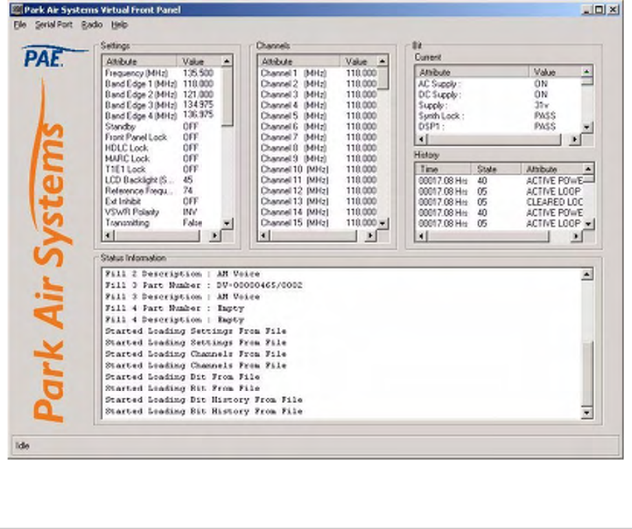
Virtual Front Panel
The VFP software supplied on CD with the radio is compatible with any PC or laptop running Windows
2000™ or Windows XP™. The VFP allows changes to a radio’s settings and channel information, it
displays the current BIT state, displays BIT history, allows security locks to be set, and provides
maintenance facilities. A typical VFP presentation is shown in Fig 5. Using the VFP has several
advantages over setting a radio from the front panel; these are:
❑A profile of the operational settings and channel information can be created, stored on disk, and
then recalled to download into other radios
❑A printout of the radio’s profile can be made from the VFP
❑The front panel controls can be locked. Front Panel Lock is available only when using the VFP.
Fig 5 Typical VFP Presentation
Intentionally Blank
Specification

T6T 300 Watt VHF Transmitter Page 22 Specification
General Specification
The general specification applies to the transmitter irrespective of the selected operating mode.
Variants
Only one variant of the T6T 300 watt transmitter is available as detailed in Table 2.
Number of Channels
The transmitter has a multichannel capability. 100 channels can be stored and recalled.
Frequency Accuracy
The frequency accuracy is better than 0.3 ppm.
Power Requirements
The transmitter operates from an ac mains supply, or a dc input supply. When both supplies are
connected, the dc input acts as an automatic backup for the ac mains.
ac input supply The transmitter operates from a 48 to 62 Hz single-phase ac supply
and automatically adjusts to operate from any supply voltage ranging
from 110 Vac to 230 Vac ±10%. The power consumption figures are
given in Table 3.
dc input supply The transmitter operates from a dc input supply between 21.6 and
32 V (measured at the radio’s input). Current loading is given in
Table 3.
Table 2 300 Watt T6T Transmitter
Description Part Number Frequency Range Special Applications
300 watt, standard frequency coverage,
high stability, VHF transmitter
B63300HS 118 to 136.975 MHz Supports 5-offset carrier
operation
Table 3 Power Consumption
Requirement Normal Operation
ac dc
Maximum 3000 VA 75 A
Typical 2100 VA 60 A
Not Transmitting 350 VA 3.5 A

T6T 300 Watt VHF Transmitter Page 23 Specification
Dimensions and Weight
The transmitter consists of one drive assembly, three amplifiers and a combiner.
Transmitter
The dimensions and weights quoted below are for a complete transmitter (that is a drive assembly plus
three amplifiers):
Width 483 mm (19 inches).
Height 622.3 mm (24.5 inches). The height occupies 14U of equipment
cabinet space.
Depth 430 mm (16.9 inches) measured from front panel to rear panel.
465 mm (18.3 inches) measured from front panel to rear RF
connectors.
Weight 79 kg (174 pounds).
Combiner
The dimensions of the combiner, including connectors, are:
Width 205 mm (8 inches).
Height 180 mm (7 inches).
Depth 85 mm (3.4 inches).
Weight 1 kg (2.2 pounds).
Environmental
Temperature range The transmitter operates to specification across the temperature
range of -20°C to +55°C.
The transmitter can be stored at temperatures ranging from
-30°C to +70°C without causing any damage.
Humidity The transmitter operates to specification at a relative humidity
between 5% and 90% non-condensing.
Altitude The transmitter operates to specification up to 15,000 feet.
Additionally it is capable of storage at altitudes up to 50,000 feet
without damage.
Shock and vibration The transmitter complies with shock and vibration protection
MIL-STD-810E, method 516.4, procedure VI - Bench Handling.
Ventilation The transmitter is cooled by six integral fans that normally run at half
speed. At an RF PA temperature of 45°C this is increased to full speed
and at 40°C it reduces to half speed again.
The transmitter power supply units also use internal fans.
Warm up time The transmitter is fully operational within 20 seconds but can take up
to 10 minutes to achieve frequency accuracy for offset carrier.

T6T 300 Watt VHF Transmitter Page 24 Specification
AM Modes
The transmitter can operate in AM-Voice mode (standard) and AM-MSK mode (optional). The following
specifications apply to both modes unless stated otherwise. ETSI test methods specified in EN 300 676
are used where applicable.
Transmitter RF Characteristics
Output Impedance
50 ohm via an N-type connector.
RF Power Output
The RF carrier output power is adjustable in 6 W steps from 30 W to 300 W. As an option, the maximum
selectable power can be limited. Output power is automatically controlled under the following conditions:
Frequency range Variations in power remain within -0.5 to +1 dB over the operational
frequency range.
Low supply voltage Variations in power remain within ±1 dB for supply voltages between
27 Vdc and 32 Vdc. For voltages less than 27 Vdc the power
progressively reduces by up to 3 dB. When the minimum dc voltage
level is reached, the transmitter dekeys.
High VSWR Loop error can reduce power progressively by up to 3 dB. Variations
in power remain within ±1 dB into a VSWR of up to 2.5:1. At a VSWR
greater than this the output power may be reduced by 10 dB ±1 dB.
High RF PA temperature If the RF PA temperature sensor exceeds 80°C the output power is
reduced by 3 dB ±1 dB. If the RF PA temperature sensor exceeds
90°C the transmitter is de-keyed and automatically re-keyed at 70°C.
Amplifier failure If one of the three amplifiers fails, the transmitter continues to operate
at 66% of the original set power.
Rise time The power rise time from a keying contact to 90% of full power is less
than 50 ms.
Duty Cycle
Both modes 100% continuous operation.
Channel Spacing
AM-Voice mode The transmitter is capable of both 25 kHz channel spacing and
8.33 kHz channel spacing.
AM-MSK mode 25 kHz.
Offset Carrier
AM-Voice mode The transmitter is capable of offsetting the carrier frequency to provide
2, 3, 4 and 5-offset carrier.
AM-MSK mode Offset carrier is not available.
Harmonic Outputs
All harmonic outputs are less than -80 dBc.

T6T 300 Watt VHF Transmitter Page 25 Specification
Spurious Outputs
Both modes The spurious outputs are less than -46 dBm for modulation depths up
to 90%, measured more than 500 kHz from carrier in the frequency
range 9 kHz to 4 GHz. There are no coherent spurious outputs above
the spectral mask at less than 500 kHz.
Intermodulation
Both modes Intermodulation products, caused by an interfering signal with the
same power as the transmitter isolated by 30 dB, are at least -40 dBc
at ≥±150 kHz and -50 dBc at ≥±500 kHz.
Transmitter Modulation Characteristics
Mode
AM-Voice AM-Voice mode uses Double Sideband (DSB) Amplitude Modulation
(AM) full carrier; emission designator 6K80A3EJN for 25 kHz
channels and 5K00A3EJN for 8.33 kHz channels.
AM-MSK AM-MSK mode uses Double Sideband (DSB) Amplitude Modulation
(AM) full carrier; emission designator 13K0A2DJN.
Modulation Depth
Both modes The transmitter modulation can be set to a maximum of 95%.
Hum and Noise
Both modes The hum and noise is more than 45 dB below the signal level for line
input levels <-13 dBm, and more than 50 dB below the signal level for
line input levels ≥-13 dBm, for a carrier modulated by a 1 kHz signal
with a modulation depth of 90%.
Frequency Response
25 kHz channel spacing AM-Voice and AM-MSK: The variation in frequency response with
reference to a 1 kHz signal is within +0.5 dB and -1.5 dB across the
frequency range 300 to 3400 Hz. The response is also less than
-20 dB at 100 Hz and below, and less than -30 dB at 4 kHz and above.
8.33 kHz channel spacing AM-Voice only: The variation in frequency response with reference to
a 1 kHz signal is within +0.5 dB and -1.5 dB across the frequency
range 350 Hz to 2500 Hz. The response is also less than -10 dB at
100 Hz and below, and less than -30 dB at 3200 Hz and above.
Distortion
25 kHz channel spacing The total harmonic distortion is less than 5% due to signals with a
modulation depth of 90%, within the frequency range 300 Hz to
3400 Hz.
8.33 kHz channel spacing AM-Voice only: The total harmonic distortion is less than 5% due to
signals with a modulation depth of 90%, within the frequency range
350 Hz to 2500 Hz.
Under extreme conditions, when the loop error protection circuit is
active, the distortion is maintained at less than 10%.

T6T 300 Watt VHF Transmitter Page 26 Specification
Residual FM
Both modes For a test signal of 1 kHz set at 80% modulation depth applied to the
line input of the transmitter, the unwanted peak frequency modulation
does not exceed ±500 Hz.
VOGAD
AM-Voice mode The VOGAD has an operational range of 30 dB with the threshold
level set at 10 dB below the average speech line level setting. Within
the VOGAD range the modulation depth remains at the set level
±10%. It has an attack time of less than 20 ms and a decay time of
greater than 2 seconds, both measured with a 10 dB step to 15 dB into
VOGAD.
AM-MSK mode The VOGAD is disabled.
Mute
AM-Voice mode The mute level is set at 15 dB below the average speech line level
setting. The mute can be disabled.
AM-MSK mode The mute is disabled.
Differential Group Delay
AM-MSK mode There is less than 60 µs differential group delay for signals in the
range 1200 to 2400 Hz.
Transmitter Control
Audio Inputs
Audio can be connected to the transmitter via the front panel microphone connector or via the 600 ohm
balanced line inputs. Line level setting from -30 to +10 dBm.
PTT Time Out
The time out period is adjustable from 2 to 510 seconds in 2 second steps or it can be disabled.

T6T 300 Watt VHF Transmitter Page 27 Specification
Mode 2
Mode 2 parameters are identical to AM-Voice mode with the following exceptions.
RF Power Rise Time
The transmitter produces more than 90% of full power output within the first 2 symbols of the power
stabilization segment, which is the first segment of the training sequence and consists of 4 symbols each
representing 000.
RF Power Decay Time
The output power decays by more than 20 dB within 2.5 symbols of the middle of the final symbol.
Channel Spacing
25 kHz channel spacing only.
Transmitter Modulation Characteristics
Mode 2 uses Carrier Sense Multiple Access (CSMA) differentially encoded 8-phase shift keying
(D8PSK), using a raised cosine filter with α=0.6 (nominal value), emission designator 14K0G1DE.
Information is differentially encoded with 3 bits per symbol transmitted as changes in phase rather than
absolute phase. The data stream is divided into groups of 3 consecutive data bits, least significant bit
first. Zeros are padded to the end of transmissions if needed for the final channel symbol.
Modulation Rate
The symbol rate is 10,500 symbols/second (±0.005%), resulting in a nominal bit rate of 31,500 bits/s.
RMS Phase Error
The RMS phase error is less than 3°. The error vector magnitude is less than 6%.
Phase Acceleration
The total frequency change during the transmission of the unique word is less than 10 Hz. After this, the
phase acceleration is less than 500 Hz/s.
Transmitter Control
All control information and data for transmission is transferred via the HDLC connector. Control
information to an associated receiver is passed via the T1/E1 connector. Data from the receiver is also
passed back via the T1/E1 connector and then transferred to the Mode 2 computer via the HDLC
connector. This is illustrated in the Installation topic of this CD.
Time Out
The transmitter automatically dekeys if a transmission exceeds 10 seconds. No fault is flagged and the
transmitter keys again for the next transmission.

T6T 300 Watt VHF Transmitter Page 28 Specification
Mode 3
Mode 3 parameters are identical to AM-Voice mode with the following exceptions.
RF Power Rise Time
The transmitter produces more than 90% of full power output within the first 2 symbols of the power
stabilization segment, which is the first segment of the training sequence and consists of 4 symbols each
representing 000.
RF Power Decay Time
The output power decays by more than 20 dB within 2.5 symbols of the middle of the final symbol.
Channel Spacing
25 kHz channel spacing only.
Transmitter Modulation Characteristics
Mode 3 uses Time Division Multiple Access (TDMA) differentially encoded 8-phase shift keying (D8PSK),
using a raised cosine filter with α=0.6 (nominal value), emission designator 14K0G7WET. Information is
differentially encoded with 3 bits per symbol transmitted as changes in phase rather than absolute phase.
The data stream is divided into groups of 3 consecutive data bits, least significant bit first. Zeros are
padded to the end of transmissions if needed for the final channel symbol.
Modulation Rate
The symbol rate is 10,500 symbols/second (±0.005%), resulting in a nominal bit rate of 31,500 bits/s.
RMS Phase Error
The RMS phase error is less than 3°. The error vector magnitude is less than 6%.
Phase Acceleration
The total frequency change during the transmission of the unique word is less than 10 Hz. After this, the
phase acceleration is less than 500 Hz/s.
Transmitter Control
All control information and data for transmission is transferred via the T1/E1 connector. This is illustrated
in the Installation topic of this CD.
Operation

T6T 300 Watt VHF Transmitter Page 30 Operation
Overview
This topic describes the transmitter’s controls and indicators and details how to adjust the operational
settings.
The transmitter comprises a drive assembly, three amplifiers and a combiner. All operational settings are
made at the drive assembly’s front panel.
T6T 300 Watt VHF Transmitter Page 31 Operation
T6T VHF Amplifier
There are no operating controls fitted to the amplifier. All operational settings are made at the drive
assembly.
The amplifier has three front panel indicators as detailed in Fig 6 and a rear panel Supply switch. Should
an amplifier fail, shown by the Alarm indicator being lit, the transmitter continues to operate at reduced
power (200 watts).
Fig 6 T6T VHF Amplifier Front Panel Indicators
Ready. A green indicator that lights when the amplifier is ready for
use and no BIT faults have been detected.
Alarm. A red indicator that lights when a BIT fault has been
detected.
Transmit. An amber indicator that lights when the transmit circuit is
keyed and the amplifier is producing output power.
T6T 300 Watt VHF Transmitter Page 32 Operation
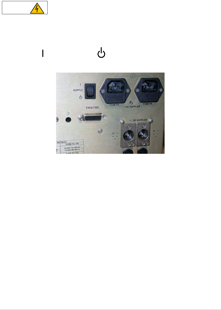
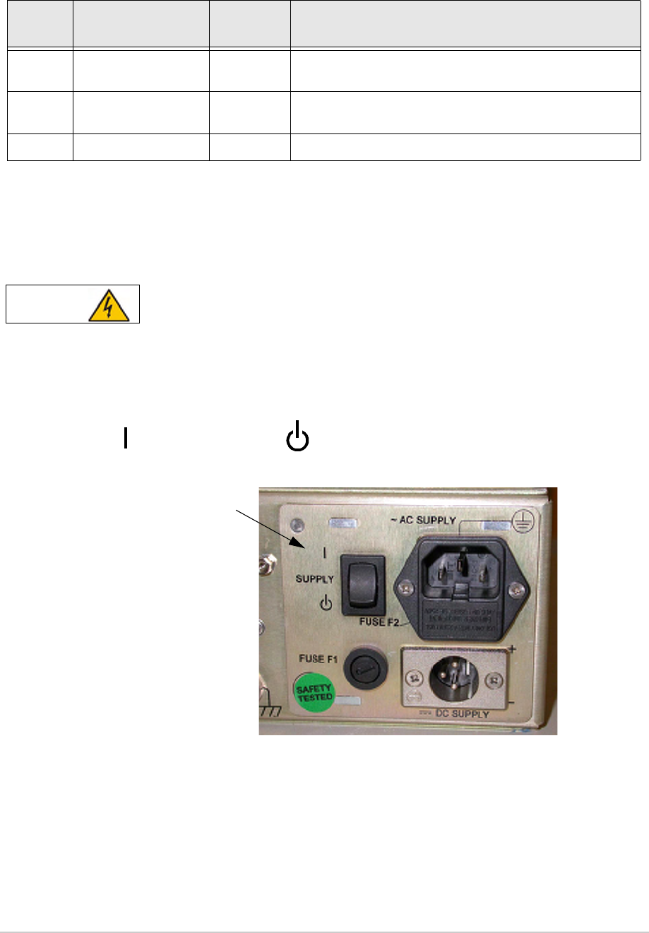
Rear Panel Supply Switch
The rear panel Supply switch (Fig 7) is a 2-way rocker switch used to select between power on, and
standby.
When the Supply switch is set to the Standby position, dangerous voltage is still present in
the internal power supply circuitry. To ensure safe working, the amplifier must be isolated
from the ac and dc input supplies.
Fig 7 Rear Panel Supply Switch
WARNING Dangerous Voltage
= Standby= On
T6T 300 Watt VHF Transmitter Page 33 Operation
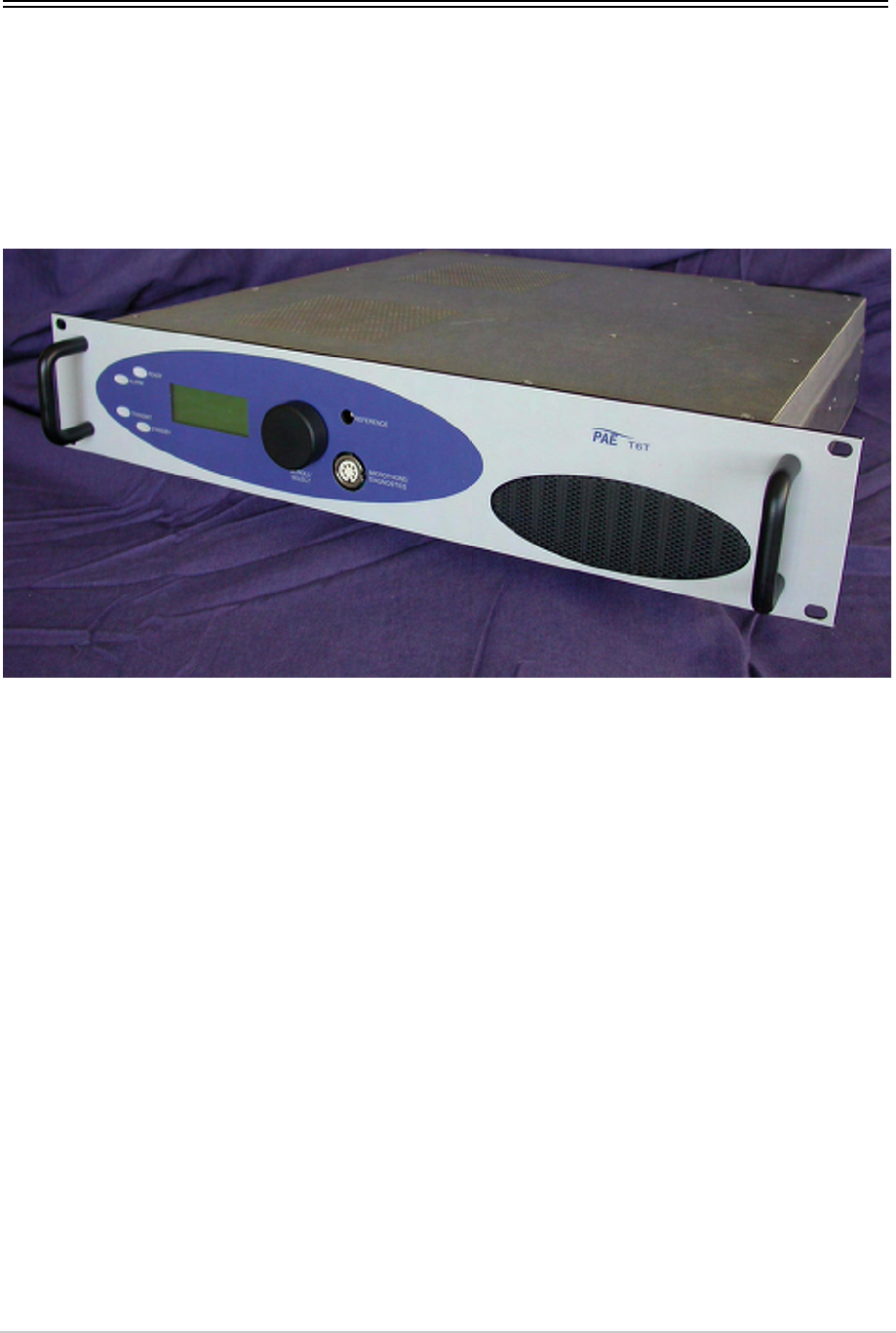
Drive Assembly
The transmitter’s operational settings are made from the drive assembly’s front panel (Fig 8). The
following pages describe the controls and detail how to set up the transmitter to suit the operational
requirement.
No attempt to set up the transmitter must be made until all procedures detailed in the Installation topic
have been completed.
Fig 8 T6T Drive Assembly

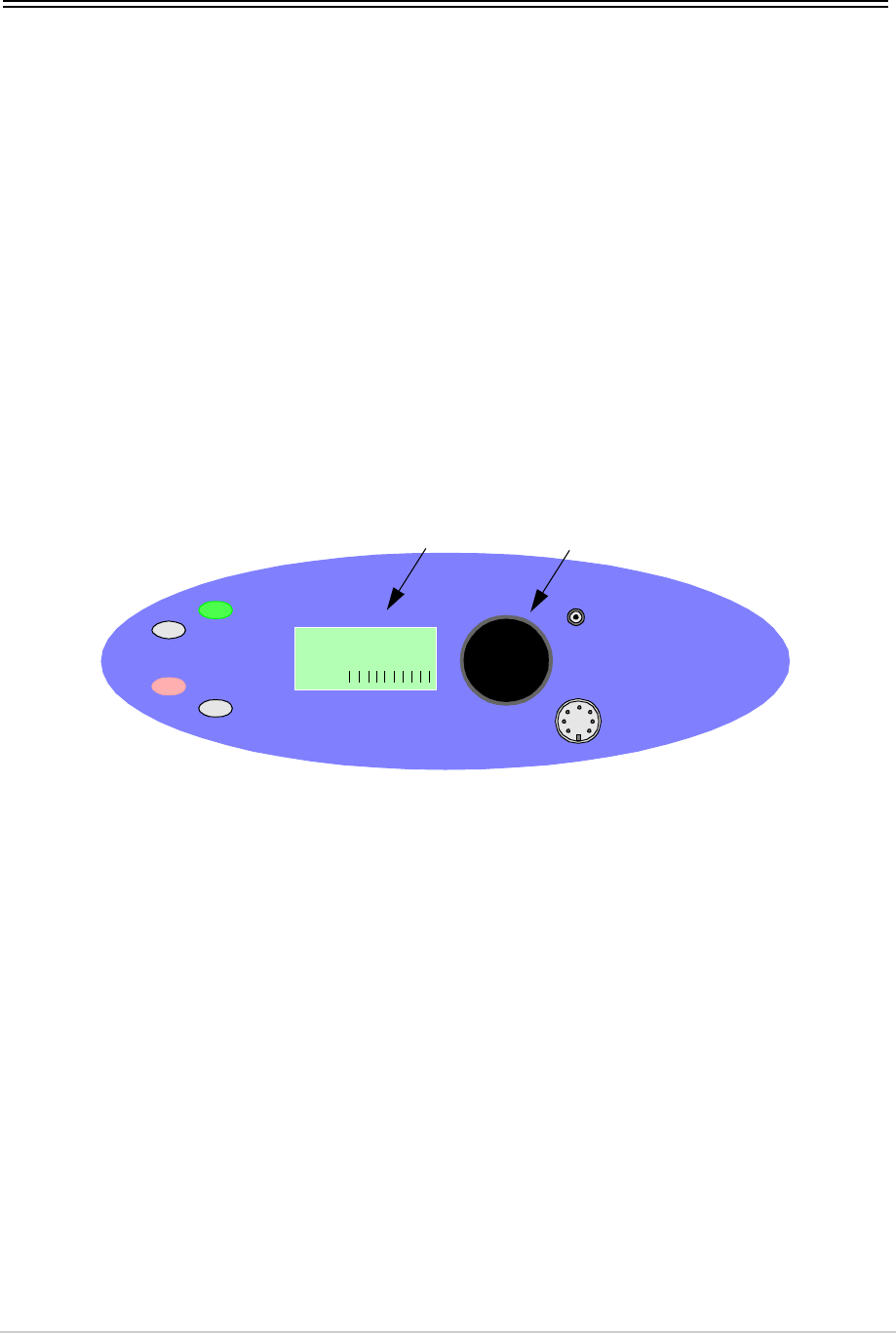
T6T 300 Watt VHF Transmitter Page 34 Operation
Front Panel Controls and Indicators
The drive assembly front panel controls and indicators are shown in Fig 9.
Fig 9 Front Panel Controls and Indicators
Scroll/Select Switch and LCD
The Scroll/Select switch is used in conjunction with the Liquid Crystal Display (LCD) to select most of the
transmitter's operational settings. During normal operation, the LCD shows the operating frequency, the
channel number (if the channel store facility is used), the offset carrier (if used), and displays a graphical
representation of instantaneous peak power.
The example LCD screen above shows the transmitter operating on 118.000 MHz; the frequency has
been preset as channel 100 and offset at +7.3 kHz.
Ready Indicator
A green indicator that lights when the transmitter is ready for use and no BIT faults have been detected.
Transmit Indicator
An amber indicator that lights when the transmit circuit is keyed and producing output power.
Alarm Indicator
A red indicator that either flashes, or lights, when a BIT fault has been detected. BIT indications are
classified as either Alarms or Alerts.
If an ‘alert’ condition is detected, the Alarm indicator flashes, the Ready indicator remains lit, and the
transmitter remains operational. A BIT ‘alert’ is indicated if:
❑The transmitter RF output power has reduced from its setting by more than 1 dB but not more than
3 dB
❑The supply volts falls below a pre-defined level.
Any other BIT condition results in an alarm. When detected, the Alarm indicator lights and the Ready
indicator becomes unlit; the transmitter cannot be used.
READY
ALARM
TRANSMIT
STANDBY SCROLL/
SELECT
MICROPHONE/
DIAGNOSTICS
REFERENCE
F r e q 1 1 8 .0 0 0 M H z
C h 1 0 0 + 7 . 3 k H z
P w r
Scroll/Select SwitchLCD
M o d e A M V o i c e 1
T6T 300 Watt VHF Transmitter Page 35 Operation
Standby Indicator
A red indicator that lights when the transmitter is in standby mode. When in standby mode, most of the
radio's circuits are inactive, the front panel LCD is blanked, and the transmitter cannot be keyed.
Standby mode is selected and deselected using the front panel Scroll/Select switch and LCD, by initiating
an instruction through a MARC system, through a T6 controller or through the VFP. For details of front
panel selection and deselection see page 46.
Reference Connector
An SMB jack socket that allows a frequency counter to monitor the transmitter's reference frequency.
This connector is used only for maintenance purposes. The instructions for checking and adjusting the
reference frequency are given in the Maintenance topic.
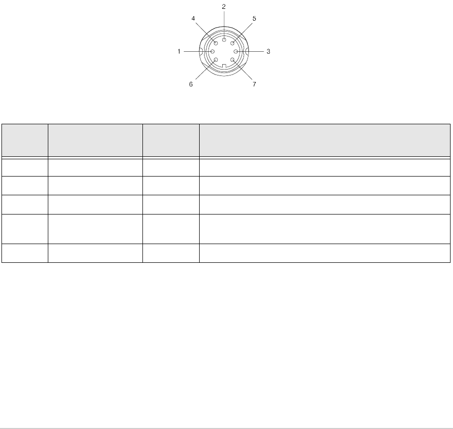
Microphone/Diagnostics Connector
A dual purpose connector that allows either a microphone, or a PC, to be connected to the transmitter.
The connector is a 7-pin self-locking DIN socket; the pin-out is shown in Table 4.
A microphone is fitted to this connector to enable the transmitter to be operated in AM local mode. The
connections are detailed in Table 4. A PC can also be connected to allow the VFP to be displayed. Using
the VFP is detailed in the Maintenance topic. The PC connections at the transmitter are shown in Table 5.
Table 4 Microphone/Diagnostics Connector - Audio Connections
Pin
Number Signal Input or
Output Description
1 Microphone ground - 0 V.
3 Microphone PTT Input 0 V to PTT.
5 Sidetone Output 0 to 3 V pk-pk.
6 Microphone input Input 2 to 35 mV rms on Passive setting and 8 to 140 mV rms on
Active setting to remain in VOGAD range.
7 Ground - 0 V.
Viewed from front
T6T 300 Watt VHF Transmitter Page 36 Operation
Rear Panel Supply Switch
The rear panel Supply switch (Fig 10) is a 2-way rocker switch used to select between power on, and
standby.
When the Supply switch is set to the Standby position, dangerous voltage is still present in
the internal power supply circuitry. To ensure safe working, the drive assembly must be
isolated from the ac and dc input supplies.
Fig 10 Drive Assembly Supply Switch
Table 5 Microphone/Diagnostics Connector - PC Connections
Pin
Number Signal Input or
Output Description
2 Transmit data Output RS232, 115200 baud, 8 data bits, 1 stop bit, no parity, no
handshaking.
4 Receive data Input RS232, 115200 baud, 8 data bits, 1 stop bit, no parity, no
handshaking.
7 Ground - 0 V.
WARNING Dangerous Voltage
= Standby= On
Supply Switch
T6T 300 Watt VHF Transmitter Page 37 Operation
Setting Up and Operation
Setting up the transmitter involves using the front panel Scroll/Select switch to specify the operating
parameters.
Operating parameters can also be set using the Virtual Front Panel (VFP), through a Multi-Access
Remote Control (MARC) system, or from an associated T6 controller. VFP operation is described on this
CD under Maintenance; MARC and T6 controller functionality is described in separate documentation.
Table 12 on page 63 details the functions and parameters that can be set from all sources.
No attempt to set up the transmitter should be made until the installation procedures, given in the
Installation topic, are completed.
Normal Operation
During normal operation, the LCD displays the Main screen. This screen shows the operating frequency,
the channel number (if the channel store facility is used), the offset carrier (if used), and displays a
graphical representation of output power when the transmitter is keyed. If the transmitter has been set to
Standby mode, which is shown by the front panel Standby indicator being lit, the LCD is blanked.
Using the Scroll/Select Switch
The Scroll/Select switch (referred to throughout this topic as the ‘Switch’) is used to leave the Main
screen and display the Control screen (see page 40). Further use of the Switch displays various selection
menus and allows the required parameters to be set. The switch has three actions: it can be turned
clockwise, anti-clockwise, or momentarily pushed in.
READY
ALARM
TRANSMIT
STANDBY SCROLL/
SELECT
MICROPHONE/
DIAGNOSTICS
REFERENCE
F r e q 1 1 8 .0 0 0 M H z
C h 1 0 0 + 7 . 3 k H z
P w r
Scroll/Select SwitchLCD
M o d e A M V o i c e 1

T6T 300 Watt VHF Transmitter Page 38 Operation
Screen Protocol
The following protocol is applicable to all screens described in this document.
Main screen During normal operation, the Main screen (an example of which is shown below
whilst the transmitter is transmitting) is displayed.
Switch Refers to the front panel Scroll/Select switch. The switch is turned clockwise to scroll
through fields from left to right, and from top to bottom. The switch is turned
anti-clockwise to scroll through fields from right to left, and from bottom to top. The
switch is pressed to make a selection.
Time out If during any setting up procedure the Scroll/Select switch is not operated for
30 seconds, the display returns to the Main screen. If editing any parameter has not
been completed, the transmitter stays on the original setting.
>> Indicates more fields are available other than those currently displayed. To access
those fields, turn the switch clockwise through the last displayed field.
<< Indicates more fields are available other than those currently displayed. To access
those fields, turn the switch anti-clockwise through the first displayed field.
Back When Back is selected, you are returned to the previous menu.
Exit When Exit is selected, you are returned to the Main screen.
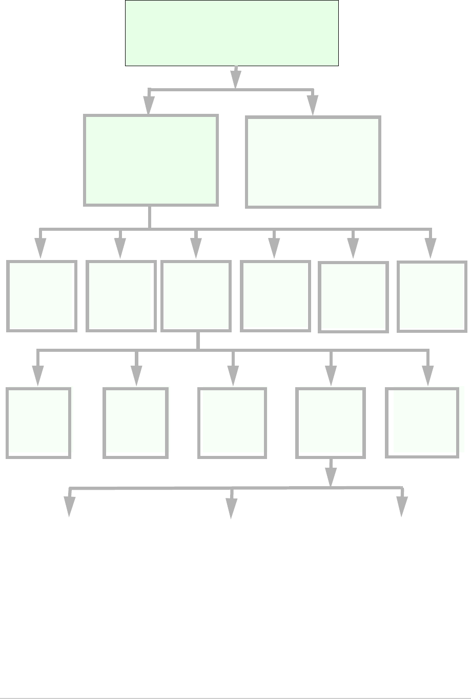
Menu System
The front panel control of the radio is implemented through a hierarchical menu system as shown on the
following page.
F r e q 1 1 8 . 0 0 0 M H z
C h 1 0 0 + 7 . 3 k H z
M o d e A M V o i c e
Pwr IIIIIIIIII
T6T 300 Watt VHF Transmitter Page 39 Operation
Menu System
F r e q 1 1 8 . 0 0 0 M H z
Ch100
M o d e A M V o i c e
Pwr IIIIIIIIII
Settings
Set the
transmitter
operational
settings
BIT
Initiate a BIT
test and view
results
Standby
Enter or exit
standby mode
Ref Freq
Adjust the
transmitter
reference
frequency
Band Edges
Set up the
transmitter
band edges
Polarities
Set the active
polarity for
certain hardwire
connections
Backlight
Adjust the
LCD’s
backlight
AM-Voice Mode
Settings
(see page 49)
AM-MSK Mode
Settings
(see page 51)
Digital Modes
(see page 52)
Mode and
Mode
Settings
Select mode
Menu Lock Screen
Main Screen
(Example)
Displayed during normal
transmitter operation
Frequency
Set the
transmitter
operating
frequency
Channel
Set or recall up
to 100 preset
frequency
channels
Control Screen
Configure the transmitter
operating parameters, access
the BIT facility or view the
software configuration
S/W Config
View the
transmitter
software
configuration

T6T 300 Watt VHF Transmitter Page 40 Operation
Menu Lock Screen
A security facility available only from the VFP allows the drive assembly front panel to be ‘locked’. When
this facility is active, no operational settings can be made from the front panel until an ‘unlock’ command
is sent from the VFP.
The following screen is displayed when ‘lock’ is active, and the front panel switch is pressed.
To exit the system lock screen:
❑Select OK, then press the switch. You are returned to the Main screen
or,
❑Wait for the 30 second time out to expire. You are returned to the Main screen.
Control Screen
The Control screen is entered from the Main screen by pressing the switch. The following screen is
displayed:
S E C U R I T Y M E S S A G E
F r o n t P a n e l
L o c k e d
O K
F r e q u e n c y
C h a n n e l
S e t t i n g s
E x i t > >
B I T
S / W C o n f i g
S t a n d b y
E x i t < <
Change the transmitter operating frequency.
Store or recall preset channel frequencies.
Select operating mode and mode settings.
Initiate a BIT test and view results.
View software configuration.
Enter or exit standby mode.

T6T 300 Watt VHF Transmitter Page 41 Operation
Notes for Setting Up the Transmitter
The following notes should be read before setting up the transmitter. They advise on the special
frequency display when using 8.33 kHz channel spacing, and give guidance on the optimum line level
settings. Note that for operation in the United States of America, this equipment is certified only for
operation using 25 kHz channel spacing.
Front Panel Display for 25 kHz and 8.33 kHz Channel Spacing
When setting the operating frequency of the transmitter and 8.33 kHz channel spacing is required, the
displayed frequency differs from the actual channel frequency. Table 6 shows the pattern used for
25 kHz and 8.33 kHz spaced channel frequencies from 118.000 MHz to 118.141 MHz. The pattern is the
same for any frequency within the transmitter's frequency range. The display conforms to ICAO
convention for 8.33 kHz operation.
Table 6 25 kHz and 8.33 kHz Channel Spacing Displays
Actual Frequency
(to 4 decimal places) Channel Spacing Displayed Frequency
at Drive Assembly's Front Panel
118.0000 MHz
118.0000 MHz
118.0083 MHz
118.0166 MHz
118.0250 MHz
118.0250 MHz
118.0333 MHz
118.0416 MHz
118.0500 MHz
118.0500 MHz
118.0583 MHz
118.0666 MHz
118.0750 MHz
118.0750 MHz
118.0833 MHz
118.0916 MHz
118.1000 MHz
118.1000 MHz
118.1083 MHz
118.1166 MHz
118.1250 MHz
118.1250 MHz
118.1333 MHz
118.1416 MHz
25 kHz
8.33 kHz
8.33 kHz
8.33 kHz
25 kHz
8.33 kHz
8.33 kHz
8.33 kHz
25 kHz
8.33 kHz
8.33 kHz
8.33 kHz
25 kHz
8.33 kHz
8.33 kHz
8.33 kHz
25 kHz
8.33 kHz
8.33 kHz
8.33 kHz
25 kHz
8.33 kHz
8.33 kHz
8.33 kHz
118.000 MHz
118.005 MHz
118.010 MHz
118.015 MHz
118.025 MHz
118.030 MHz
118.035 MHz
118.040 MHz
118.050 MHz
118.055 MHz
118.060 MHz
118.065 MHz
118.075 MHz
118.080 MHz
118.085 MHz
118.090 MHz
118.100 MHz
118.105 MHz
118.110 MHz
118.115 MHz
118.125 MHz
118.130 MHz
118.135 MHz
118.140 MHz

T6T 300 Watt VHF Transmitter Page 42 Operation
Line Level Setting
The input line level setting displayed on the front panel is equivalent to the average speech level with a
peak-to-average ratio of 13 dB. This corresponds to the level specified for the lines.
When testing the transmitter using a sine wave, the line input level should be set to 10 dB above the line
level setting. The VOGAD and mute thresholds are preset at 10 dB and 15 dB respectively below the line
level setting.
Table 7 shows the relationship between the input line level, VOGAD threshold and mute threshold.
Offset Carrier Operation
This transmitter can be set to operate using a 2, 3, 4 or 5-offset carrier system as follows:
❑With 2-offset carrier working, the carriers are spaced at ±5 kHz
❑With 3-offset carrier working, the carriers are spaced at zero and ±7.3 kHz
❑With 4-offset carrier working, the carriers are spaced at ±2.5 kHz and ±7.5 kHz
❑With 5-offset carrier working, the carriers are spaced at zero, ±4 kHz and ±8 kHz. [5-offset carrier
is available only on HS transmitter variants.]
If using a 2, 3 or 4-offset carrier system, the appropriate offset is selected from the AM-Voice mode
settings screen. After selection, no further action is required.
If using a 5-offset carrier system, the appropriate offset (-4 kHz, +4 kHz, -8 kHz or +8 kHz) is selected
from the AM-Voice mode settings screen. After selection, the procedure titled ‘Setting a 5-Offset Carrier
Frequency’ must be completed; this procedure is found in the Maintenance topic.
Table 7 Relationship Between Line Level, VOGAD Threshold and Mute Threshold
Line Level Setting
(dBm) Average Speech
Level (dBm) Sine Wave Level
(dBm) VOGAD Threshold
(dBm) Mute Threshold
(dBm)
+10 +10 +20 0 -5
+5 +5 +15 -5 -10
00+10-10-15
-5 -5 +5 -15 -20
-10 -10 0 -20 -25
-15 -15 -5 -25 -30
-20 -20 -10 -30 -35
-25 -25 -15 -35 -40
-30 -30 -20 -40 -45

T6T 300 Watt VHF Transmitter Page 43 Operation
Changing the Transmitter’s Operating Frequency
The transmitter’s frequency can be changed in two ways: either from the frequency screen, or by
recalling a preset channel. This procedure details the use of the Frequency screen.
F r e q 1 1 8 . 0 0 0 M H z
C a n c e l O K
(1) From the Control screen, select
frequency to display the Frequency
screen.
(2) Turn the switch to highlight the digit to
be changed, then press the switch.
(3) Turn the switch until the required digit
is shown, then press the switch.
(4) Repeat until the required frequency is
shown, then highlight OK and press the
switch.
(5) Only frequencies that fall between the
band edge settings (see page 61) can
be selected.

T6T 300 Watt VHF Transmitter Page 44 Operation
To Store and Recall Frequency Channels
Up to 100 frequency channels can be stored in the transmitter.
C h 1 0 0
F r e q 1 2 1 . 5 0 0 M H z
R e c a l l
B a c k E x i t
C h 1 0 0
F r e q 1 1 8 . 0 0 0 M H z
S t o r e
B a c k E x i t
C h 1 0 0
F r e q 1 1 8 . 0 0 0 M H z
I n v a l i d f o r M o d e
B a c k E x i t
C h 1 0 0
F r e q 1 1 8 . 0 0 0 M H z
O u t s i d e B a n d E d g e
B a c k E x i t
To Store a Channel Frequency:
(1) From the Control screen, select
Channel to display the Channel
screen. Highlight Channel, press the
switch and then turn it until the required
channel number is displayed; press the
switch.
(2) Highlight the MHz frequency value
(see Example 2) press the switch and
then turn it until the required MHz value
is shown. Press the switch.
(3) Highlight the kHz frequency value (see
Example 3), press the switch and then
turn it until the required kHz value is
shown. Press the switch.
(4) Highlight Store and press the switch.
The new frequency is now stored in the
selected channel number.
To Recall a Stored Frequency Channel:
(1) From the Control screen, select
Channel to display the Channel
screen.
(2) To make the transmitter operate on
any preset channel frequency,
highlight Channel and press the switch.
Turn the switch until the required
channel number/frequency is
displayed, then press the switch.
(3) Turn the switch to highlight Recall, then
press the switch. Exit the screen. The
transmitter now operates on the
recalled channel frequency.
Notes:
If a frequency outside the band edge limits is
entered, a message (see Example 3) is
displayed.
If a frequency not valid for the mode of
operation is entered, a message (see
Example 4) is displayed.
Channel Screen - Example 1
Channel Screen - Example 2
Channel Screen - Example 3
Channel Screen - Example 4

T6T 300 Watt VHF Transmitter Page 45 Operation
To Initiate a BIT Test
Use the following procedure to initiate an interruptive BIT test from the drive assembly front panel. A BIT
test cannot be initiated while the transmitter is keyed. After a BIT test has been run, the BIT screen is
displayed (see AM-Voice and AM-MSK BIT Screen on page 57). An interruptive BIT test cannot be
initiated in Mode 2 or Mode 3.
(1) From the Main screen, press the switch to display the Control screen. Turn the switch until BIT
is highlighted. Press the switch.
(2) Ensure the BIT menu is displayed. Turn the switch until BIT Initiate is highlighted. Press the
switch.
(3) During the test, which takes approximately two seconds, the Testing screen is displayed.
B I T I n i t i a t e
E T I 0 0 0 0 0 : 0 0 h r s
A C S u p p l y O N
E x i t > >
T e s t i n g
P l e a s e W a i t
During an interruptive BIT test, the transmitter radiates modulated carrier waves at the set power.
Users should therefore obtain the necessary authority before initiating a test.
If the test is to be carried out with the antenna disconnected, ensure a load is fitted to the
transmitter's antenna connector.
In order to test the line input stages, an internally generated 1 kHz tone is injected into the line input
circuit. Any other audio present on the line input will cause the test to be inaccurate. Therefore the
transmitter MUST NOT be keyed during the test.
B I T
S / W C o n f i g
St andby
E x i t < <

T6T 300 Watt VHF Transmitter Page 46 Operation
(4) On completion, and if the interruptive test was initiated from the front panel, one of the following
screens will be shown.
(5) Selecting OK takes the user back to the BIT screen. The user can then scroll through the screen
to check out transmitter parameters for failure.
Standby Mode
Standby mode is a power saving feature that can be used for non-operational transmitters. When in
standby mode, most of the transmitter's circuits are inactive, the LCD is blanked, and the transmitter
cannot be keyed. To put the transmitter into standby mode, use the following procedure.
When the transmitter is in Standby mode, the red front panel Standby indicator is lit.
To Enter Standby Mode
To Exit Standby Mode
T e s t S t a t u s
P A S S
O K
T e s t S t a t u s
F A I L
O K
E n t e r S t a n d b y ?
Y e s N o
(1) From the Control screen select
Standby.
(2) At the Standby screen, select Yes.
(3) Check that the LCD blanks and the
front panel Standby indicator is lit.
E x i t S t a n d b y ?
Y e s N o
(1) Press the Switch.
(2) Select Yes.
(3) Check that the Main screen is
displayed and that the front panel
Standby indicator is unlit.

T6T 300 Watt VHF Transmitter Page 47 Operation
Settings
Operational settings for the transmitter are configured at the front panel, through the VFP, or through an
associated MARC system (or compatible control system). Some settings can also be made remotely via
a T6 controller. The Settings screen is entered from the Control screen.
The settings that can be selected at the front panel Settings screen are:
❑Mode: either AM-Voice, AM-MSK, Mode 2 or Mode 3
❑Mode settings - allows the selected mode parameters to be set
❑Polarities
❑Band edges
❑Reference frequency
❑Backlight.
Note that the mode selection, reference frequency and backlight are set from this screen. When mode
settings, polarities and band edges are selected the user is taken to other screens.
General and mode specific settings, showing default values, are referenced in Table 8 on the following
page. Click on any required parameter by page number for further references.
M o d e A M V o i c e
M o d e S e t t i n g s
P o l a r i t i e s
E x i t > >
B a n d E d g e s
R e f F r e q 5 0 . 0 %
B a c k l i g h t 0 3 0 s
E x i t < < > >
B a c k
E x i t
Select AM-Voice, AM-MSK, Mode 2 or Mode 3.
Select for the mode specific Settings menu.
Select for the Polarities menu.
Select for band edge settings screen.
Align the transmitter reference frequency (Note 1).
Adjust the LCD’s backlight time out (Note 2).
Notes:
(1) Setting the transmitter reference frequency is a maintenance operation. The current value
should not be reset unless the correct test equipment is connected. See the Maintenance topic.
(2) The LCD backlight can be set for permanently on, off, or timed to stay on for a period between
15 and 120 seconds.

T6T 300 Watt VHF Transmitter Page 48 Operation
Table 8 Operational Settings from the Front Panel
Parameter Mode Adjustment Range Factory Default Setting Further
Reference
Menu lock screen All Locked or unlocked Unlocked page 40
Enter standby
mode All Yes or No - page 46
Exit standby mode All Yes or No - page 46
Set mode of
operation
All AM-Voice, AM-MSK,
Mode 2 or Mode 3
AM-Voice page 47
Set polarities AM-Voice,
AM-MSK
STD or INV STD page 53
Band edges All 118.000 to 136.975 MHz 118.000 and 136.975 MHz page 61
LCD backlight All 15 to 120 s, On or Off 30 s page 47
RF power All 30 to 300 W (6 W steps) 300 W page 49 and
page 51
Audio line in level AM-Voice,
AM-MSK
-30 to +10 dBm -13 dBm page 49 and
page 51
Inhibit AM-Voice,
AM-MSK
On or Off Off page 49 and
page 51
PTT (key) AM-Voice,
AM-MSK
On (key) or Off (de-key) Off page 49 and
page 51
Tx time out AM-Voice,
AM-MSK
2 to 510 s or Off 180 s page 49 and
page 51
Modulation depth AM-Voice,
AM-MSK
5 to 95% 85% page 49 and
page 51
Mute AM-Voice On or Off On page 49
VOGAD AM-Voice On or Off On page 49
Antenna C/O delay AM-Voice
AM-MSK
On or Off
On or Off
On
Off
page 49
page 51
Offset AM-Voice 0, ±2.5, ±4, ±5, ±7.3, ±7.5
or ±8 kHz
0 (No offset) page 50
Step AM-Voice 8.33 kHz, 25 kHz or both 25 kHz page 50
Mic AM-Voice Active or Passive Passive page 50
Key priority AM-Voice,
AM-MSK
Local-Remote or
Remote-Local
Local-Remote page 50 and
page 51
Local PTT AM-Voice,
AM-MSK
Enabled or Disabled Enabled page 50 and
page 51
Remote PTT AM-Voice,
AM-MSK
Enabled or Disabled Enabled page 50 and
page 51
Remote phantom
PTT
AM-Voice,
AM-MSK
Enabled or Disabled Enabled page 50 and
page 51

T6T 300 Watt VHF Transmitter Page 49 Operation
AM-Voice Settings Procedure
During this procedure, the following parameters, applicable to AM-Voice operation, can be set:
❑RF power output
❑Audio line input level
❑Inhibit (on or off)
❑PTT on (key) or off (de-key)
❑Transmitter time out
❑Modulation depth
❑Mute (on or off)
❑VOGAD (on or off)
❑Antenna change-over delay (on or off)
❑Offset
❑Step
❑Mic (active or passive)
❑Key priority (local or remote)
❑Enable or disable local PTT
❑Enable or disable remote PTT
❑Enable or disable remote phantom PTT.
AM-Voice Mode Settings Screen
The AM-Voice mode setting screen is accessed from the Settings screen. Use the Scroll/Select switch
to select the parameter, then enter the required setting(s). Notes regarding optimum line levels are given
on page 42.
P o w e r 3 0 0 W
L i n e I n - 1 3 d B m
I n h i b i t O F F
E x i t > >
P T T O F F
T X T i m e o u t 1 8 0 s
M o d D e p t h 8 5 %
E x i t < < > >
M u t e O N
V O G A D O N
A n t C / O D e l O N
E x i t < < > >
Adjustments
RF power between 30 W and 300 W.
Audio line in level between -30 to +10 dBm.
On or Off.
On (key) or Off (de-key).
2 to 510 s or Off.
5 to 95%.
On or Off.
On or Off.
On or Off.

T6T 300 Watt VHF Transmitter Page 50 Operation
O f f s e t 0 . 0 k H z
S t e p 2 5 k H z
M i c P A S S I V E
E x i t < < > >
K e y P r i o r i t y L - R
L o c a l P T T E N
R e m o t e P T T E N
E x i t < < > >
R e m P h a n P T T E N
B a c k
E x i t < <
Adjustments
See Offset Carrier Operation on page 42.
25 kHz, 8.33 kHz or both.
Active or Passive.
Local-remote or Remote-local.
Enabled or Disabled.
Enabled or Disabled.
Enabled or Disabled.
Return to Settings screen.

T6T 300 Watt VHF Transmitter Page 51 Operation
AM-MSK Mode Settings Procedure
During this procedure, the following parameters, applicable to AM-MSK operation, can be set:
❑RF power output
❑Audio line input level
❑Inhibit (on or off)
❑PTT on (key) or off (de-key)
❑Transmitter time out
❑Modulation depth
❑Antenna change-over delay (on or off)
❑Key priority (local or remote)
❑Enable or disable local PTT
❑Enable or disable remote PTT
❑Enable or disable remote phantom PTT.
AM-MSK Mode Settings Screen
The AM-MSK mode setting screen is accessed from the Settings screen. Use the Scroll/Select switch to
select the parameter, then enter the required setting(s). Notes regarding optimum line levels are given
on page 42.
P o w e r 3 0 0 W
L i n e I n - 1 3 d B m
I n h i b i t O F F
E x i t > >
P T T O F F
T X T i m e o u t 1 8 0 s
M o d D e p t h 8 5 %
E x i t < < > >
A n t C / O D e l O N
K e y P r i o r i t y L - R
L o c a l P T T E N
E x i t < < > >
R e m o t e P T T E N
R e m P h a n P T T E N
B a c k
E x i t < <
Adjustments
RF power between 30 W and 300 W.
Audio line in level between -30 to +10 dBm.
On or Off.
On (key) or Off (de-key).
2 to 510 s or Off.
5 to 95%.
On or Off.
Local-remote or Remote-local.
Enabled or Disabled.
Enabled or Disabled.
Enabled or Disabled.
Return to Settings screen.

T6T 300 Watt VHF Transmitter Page 52 Operation
Mode 2 Settings Screen
This is an advisory screen. Pressing OK returns the user to the Main screen.
Mode 3 Settings Screen
This is an advisory screen. Pressing OK returns the user to the Main screen.
Mode2 par amet er s
a r e s e t v i a t h e
H L D C i n t e r f a c e
O K
M o d e 3 p a r a m e t e r s
a r e s e t v i a t h e
T 1 / E 1 i n t e r f a c e
O K

T6T 300 Watt VHF Transmitter Page 53 Operation
Polarities Screen AM-Voice and AM-MSK
A number of remote indication and control signals can be hardwire connected to the transmitter. These
signals, which can have their polarities set to standard (STD) or inverted (INV), are listed in Table 9.
The Polarities screen is accessed from the Settings screen.
AM-Voice and AM-MSK Polarity Settings
Each of ten polarity settings applicable to AM-Voice and AM-MSK can be set to the default STD
(standard) or INV (inverted) setting. The signal connections are shown in Table 9 along with the
conditions when STD or INV is selected. The settings for the PTT Reference voltage are also given.
R e a d y O u t S T D
E - B I T I n S T D
I n h i b i t I n S T D
E x i t > >
B I T S t a r t I n S T D
P T T R e f + 1 4 V
P T T I n S T D
E x i t > >
P h a n P T T I n S T D
P T T O u t S T D
F a s t P T T O u t S T D
E x i t < < > >
E x t V S W R I n S T D
A n t C / O O u t S T D
B a c k
E x i t < <

T6T 300 Watt VHF Transmitter Page 54 Operation
Table 9 AM-Voice and AM-MSK Polarity Settings
Signal Connector Polarity set to STD Polarity set to INV
Ready Out Facilities, pin 13 An open collector grounded
output when the radio is ready
to transmit and no BIT faults
are detected.
An open collector high
impedance output when the
radio is ready to transmit and
no BIT faults are detected.
E-BIT In Facilities, pin 2 TTL input. 0 V indicates an
external fault.
TTL input. 5 V indicates an
external fault.
Inhibit In Facilities, pin 10 TTL input. 0 V inhibits
transmitter operation.
TTL input. 5 V inhibits
transmitter operation.
BIT Start In Facilities, pin 11 TTL input. 0 V initiates an
interruptive BIT test.
TTL input. 5 V initiates an
interruptive BIT test.
PTT In MARC, pin 4
MARC Audio, pin 6
Active when input differs from
reference by more than 10 V.
Inactive when input differs from
reference by less than 1 V.
Maximum input level ±60 V
with respect to reference. Input
will draw no more than 6 mA,
requires at least 1 mA to
operate.
Active when input differs from
reference by less than 1 V.
Inactive when input differs from
reference by more than 10 V.
Maximum input level ±60 V
with respect to reference. Input
will draw no more than 6 mA,
requires at least 1 mA to
operate.
Phantom PTT In
(Phan PTT In)
MARC or
MARC Audio, pin 2
Active when input differs from
reference by more than 10 V.
Inactive when input differs from
reference by less than 1 V.
Maximum input level ±60 V
with respect to reference. Input
will draw no more than 6 mA,
requires at least 1 mA to
operate.
Active when input differs from
reference by less than 1 V.
Inactive when input differs from
reference by more than 10 V.
Maximum input level +60 V
with respect to reference. Input
will draw no more than 6 mA,
requires at least 1 mA to
operate.
PTT Out Facilities, pin 3 Grounding solid state relay.
+60 to -60 V, ac or dc, 100 mA
max, n/o. Activated 20 ms
(±1 ms) before the start of the
power ramp up to allow for the
antenna relay to pull-in time.
Grounding solid state relay.
+60 to -60 V, ac or dc, 100 mA
max, n/c. Activated 20 ms
(±1 ms) before the start of the
power ramp up to allow for the
antenna relay to pull-in time.
External VSWR
Input
(Ext VSWR In)
Facilities, pin 4 TTL input. 0 V active. TTL input. 5 V active.
Antenna
Change-over
(Ant C/O Out)
Facilities, pin 5
(Common, pin 6) Solid state relay. +60 to -60 V,
ac or dc, 100 mA max, n/o.
Activated 35 ms (±1 ms) before
the start of the power ramp up
to allow for the antenna relay
pull-in time.
Solid state relay. +60 to -60 V,
ac or dc, 100 mA max, n/c.
Activated 35 ms (±1 ms) before
the start of the power ramp up
to allow for the antenna relay
pull-in time.
Continued ...

T6T 300 Watt VHF Transmitter Page 55 Operation
Fast PTT Output
(antenna
change-over)
MARC Audio, pin 3 Open collector NPN transistor
grounding output, 200 mA max,
n/o.
Open collector NPN transistor
grounding output, 200 mA max,
n/c.
PTT Ref - PTT Ref can be set to +14 V,
0 V or -14 V. Maximum input
level ±60 V with respect to PTT
reference. Input will draw no
more than 6 mA, and requires
at least 1 mA to operate.
When the input PTT signal and
the PTT reference differ by
more than 10 V the radio keys.
When the input PTT signal and
the PTT reference are within
1 V, the radio dekeys.
Other conditions are
indeterminable.
PTT Ref can be set to +14 V,
0 V or -14 V. Maximum input
level ±60 V with respect to PTT
reference. Input will draw no
more than 6 mA, and requires
at least 1 mA to operate.
When the input PTT signal and
the PTT reference differ by
more than 10 V the radio
dekeys.
When the input PTT signal and
the PTT reference are within
1 V, the radio keys.
Other conditions are
indeterminable.
Table 9 AM-Voice and AM-MSK Polarity Settings (Continued)
Signal Connector Polarity set to STD Polarity set to INV

T6T 300 Watt VHF Transmitter Page 56 Operation
Mode 2 and Mode 3 Polarity Settings
Table 10 Mode 2 and Mode 3 Polarity Settings
Signal Connector Polarity set to STD Polarity set to INV
Ready Out Facilities, pin 13 An open collector grounded
output when the radio is ready
to transmit and no BIT faults
are detected.
An open collector high
impedance output when the radio
is ready to transmit and no BIT
faults are detected.
E-BIT In Facilities, pin 2 TTL input. 0 V indicates an
external fault. TTL input. 5 V indicates an
external fault.
External VSWR
Input
Facilities, pin 4 TTL input. 0 V active. TTL input. 5 V active.
R e a d y O u t S T D
E - B I T I n S T D
E x t V S W R I n S T D
E x i t > >
B a c k
E x i t
< <
Each of the three polarity settings applicable to
Mode 2 and Mode 3 can be set to the default STD
(standard) or INV (inverted) setting.
The signal connections are detailed in Table 10
along with the conditions when STD or INV is
selected.

T6T 300 Watt VHF Transmitter Page 57 Operation
AM-Voice and AM-MSK BIT Screen
The AM-Voice and AM-MSK BIT screen is accessed from the Control screen.
B I T I n i t i a t e
E T I 0 0 0 0 0 : 0 0 h r s
A C S u p p l y O N
E x i t > >
D C S u p p l y O N
Suppl y 28V
S y n t h L o c k P A S S
E x i t < < > >
P A T e m p 5 0 d e g C
P A C o o l i n g P A S S
B a s e b a n d P A S S
E x i t < < > >
R F D r i v e P A S S
P A O u t p u t P A S S
P A L o o p P A S S
E x i t < < > >
M o d D e p t h P A S S
R F F i l t e r s P A S S
VSWR PASS
E x i t < < > >
L o o p E r r o r P A S S
A u d i o I n P A S S
DSP1 PASS
E x i t < < > >
Select to initiate BIT test.
Shows elapsed time 0:00 to 99999:59 (Hrs:Min).
Shows state of ac supply (On or Off).
PA temperature -20°C to +150°C.
Pass or Fail.
Pass, Fail or Not Tested.
Pass, Fail or Not Tested.
Pass, Fail or Not Tested.
Pass, Fail or Not Tested.
Shows state of dc supply (On or Off).
dc supply 0 to 40 V, <21.6 V Alert, <19 V Alarm.
Pass or Fail (Out-of-Lock).
Pass, Fail or Not Tested.
Pass, Fail or Not Tested.
Pass, Fail or Not Tested.
Pass or Fail.
Pass, Fail or Not Tested.
Pass or Fail.

T6T 300 Watt VHF Transmitter Page 58 Operation
DSP2 PASS
X i l i n x 1 P A S S
X i l i n x 2 P A S S
E x i t < < > >
E E P R O M P A S S
S t a r t U p P A S S
C a l i b r a t i o n P A S S
E x i t < < > >
U n k e y e d P w r P A S S
E - B I T P A S S
M A R C A C T I V E
E x i t < < > >
H D L C I N A C T I V E
T 1 / E 1 I N A C T I V E
B a c k
E x i t < <
Pass or Fail.
Pass or Fail.
Pass or Fail.
Pass or Fail.
Pass or Fail.
Active or Inactive.
Pass or Fail.
Pass or Fail.
Pass or Fail.
Active or Inactive.
Active or Inactive.

T6T 300 Watt VHF Transmitter Page 59 Operation
Mode 2 and Mode 3 BIT Screen
The Mode 2 and Mode 3 BIT screen is accessed from the Control screen.
E T I 0 0 0 0 0 : 0 0 h r s
A C S u p p l y O N
D C S u p p l y O N
E x i t > >
S u p p l y 2 8 V
S y n t h L o c k P A S S
P A T e m p 5 0 d e g C
E x i t < < > >
P A C o o l i n g P A S S
VSWR PASS
L o o p E r r o r P A S S
E x i t < < > >
D S P 1 P A S S
D S P 2 P A S S
X i l i n x 1 P A S S
E x i t < < > >
X i l i n x 2 P A S S
E E P R O M P A S S
S t a r t U p P A S S
E x i t < < > >
C a l i b r a t i o n P A S S
E - B I T P A S S
M A R C A C T I V E
E x i t < < > >
Shows elapsed time 0:00 to 99999:59 (Hrs:Min).
Shows state of ac supply (On or Off).
Shows state of dc supply (On or Off).
Shows value of dc supply.
Synth lock (Pass or Fail).
Indicates the PA temperature.
Pass or Fail.
Pass or Fail.
Pass or Fail.
Pass or Fail.
Pass or Fail.
Pass or Fail.
Pass or Fail.
Pass, Fail or Not Tested.
Pass or Fail.
Pass or Fail.
Pass or Fail.
Active or Inactive.
H D L C I N A C T I V E
T 1 / E 1 I N A C T I V E
B a c k
E x i t < <
Active or Inactive.
Active or Inactive.

T6T 300 Watt VHF Transmitter Page 60 Operation
Software Configuration Screens
Software configuration screens are as follows:
T 6 V H F 1 0 0 W T X
1 1 8 - 1 3 6 . 9 7 5 M H z
H i g h S t a b i l i t y
E x i t > >
B o o t S o f t w a r e
6 5 - x x x x x x x x / v v
E x i t < < > >
B a s e S o f t w a r e
6 5 - x x x x x x x x / v v
E x i t < < > >
M o d e S o f t w a r e
6 5 - x x x x x x x x / v v
E x i t < < > >
F i l l 1 S o f t w a r e
6 5 - x x x x x x x x / v v
[ D e s c r i p t i o n ]
E x i t < < > >
The first screen defines the radio.
65-xxxxxxxx represents the software part
number and /v v represents its version.
65-xxxxxxxx represents the software part
number and /v v represents its version.
Current mode running. 65-xxxxxxxx
represents the software part number and /v v
represents its version.
65-xxxxxxxx represents the software part
number and /v v represents its version.
The transmitter has four software fills. Fills 2, 3
and 4 screens are the same format as this
example shown for Fill 1.

T6T 300 Watt VHF Transmitter Page 61 Operation
Band Edges
The frequency range of the T6T 300 watt transmitter is 118 to 136.975 MHz. If required, transmission
can be limited to either one or two smaller parts of the frequency band by setting the band edges, BE1
to BE4. Transmission is possible between BE1 and BE2 frequencies, and between BE3 and BE4
frequencies.
Table 11 Band Edge Settings
BE1 BE2 BE3 BE4
B63300HS set so that the full frequency range can be
transmitted. 118.000 136.975 118.000 136.975
Example: Transmitter set to transmit only those frequencies
in the range 120 to 130 MHz. 120.000 130.000 120.000 130.000
Example: Transmitter set to transmit only those frequencies
in the ranges 120 to 125 MHz and 130 to 135 MHz. 120.000 125.000 130.000 135.000
B E 1 1 1 8 . 0 0 0 M H z
B E 2 1 3 6 . 9 7 5 M H z
B E 3 1 1 8 . 0 0 0 M H z
E x i t > >
B E 4 1 3 6 . 9 7 5 M H z
E x i t < <
The Band Edge screen is accessed from the
Control screen.
Band edge frequencies can be set only in
increments of 25 kHz.
If the transmitter is required to operate over the
full range, the band edge parameters must be set
to the lowest and highest values in the range (see
Table 11).

T6T 300 Watt VHF Transmitter Page 62 Operation
BIT Status Warning Screens
The following shows some example BIT screens. These screens alternate with the Main screen when an
alert or alarm condition is present. Only the parameters causing the alert or alarm are displayed, and if
both an alert and alarm condition exists simultaneously only the alarm information is displayed. If multiple
parameters are signalling an alert or alarm condition, multiple screens are used to display the status
alternating with the Main screen.
A L E R T
S u p p l y 2 1 V
A L E R T
R F P o w e r R e d u c e d
L o o p E r r o r
Suppl y 21V
A L E R T
R F P o w e r R e d u c e d
P A T e m p 8 5 d e g C
A L A R M
R F P o w e r R e d u c e d
V S W R F A I L
A L A R M
R F P o w e r R e m o v e d
L o o p E r r o r F A I L
Suppl y 18V
A L A R M
R F P o w e r R e m o v e d
P A T e m p 9 5 d e g C
Alert:
There is no RF power reduction. The Alarm
indicator is flashing.
Alert:
The RF output power is reduced between 1 and
3 dB. The Alarm indicator is flashing.
Alert:
The RF output power is reduced between 1 and
3 dB. The Alarm indicator is flashing
Alarm:
The RF output power is reduced by more than
3 dB. The Alarm indicator is lit.
Alarm:
The RF output power is shut down. The Alarm
indicator is lit.
Alarm:
The RF output power is shut down. The Alarm
indicator is lit.

T6T 300 Watt VHF Transmitter Page 63 Operation
Table 12 Functions and Parameters
Function Front
Panel VFP MARC T6
Controller T1/E1 HDLC Default Setting
FREQUENCY
Change frequency ✔✔✔ ✔ ✔✔ 118.000 MHz
FREQUENCY CHANNELS
Store/Recall preset
frequency channels ✔✔✔ ✔ ✗✗ -
SETTINGS
Set modulation
mode ✔✔✔ ✔ ✔✔ AM-Voice
Radio Settings (AM Modes)
Set RF output
power ✔✔✔ ✔ ✔✔ 300 W
Set audio input line
level ✔✔✔ ✗ ✔✗ -13 dBm
Set inhibit on or off ✔✔✔ ✗ ✗✗ Off
PTT test facility
on (key), off (de-
key)
✔✔
View
state ✗✔✗ Off
Set Tx time out ✔✔✔ ✗ ✔✗ 180 s
Set modulation
depth ✔✔✔ ✔ ✔✗ 85%
Set mute on or off
(AM-Voice only) ✔✔✔ ✗ ✗✗ On
Set VOGAD on
or off
(AM-Voice only)
✔✔✔ ✗ ✗✗ On
Set antenna C/O
delay on or off ✔✔✔ ✗ ✗✗ AM-Voice - On
AM-MSK - Off
Set frequency offset
(AM-Voice only) ✔✔✔ ✗ ✗✗ 0 (No offset)
Set frequency step
size
(AM-Voice only)
✔✔ ✗ ✗ ✗✗ 25 kHz
Continued ...

T6T 300 Watt VHF Transmitter Page 64 Operation
Set microphone
type
(active or passive)
(AM-Voice only)
✔✔ ✗ ✗ ✗✗ Passive
Set keying priority
(local or remote) ✔✔ ✗ ✗ ✗✗ Local-Remote
Enable or disable
local PTT ✔✔ ✗ ✗ ✗✗ Enabled
Enable or disable
remote PTT ✔✔ ✗ ✗ ✗✗ Enabled
Enable or disable
remote phantom
PTT
✔✔ ✗ ✗ ✗✗ Enabled
Radio Settings (Digital Modes)
MAC TM1 (inter
access delay) ✗✔✗ ✗ ✗✔ 2.5 ms
MAC TM2 (channel
busy) ✗✔✗ ✗ ✗✔ 60 s
MAC p
(persistance) ✗✔✗ ✗ ✗✔ 13/256
MAC M1 (maximum
number of access
attempts)
✗✔✗ ✗ ✗✔
135
Scramble vector ✗✔✗ ✗ ✗✔ 4D4B
19787
Tx enable ✗✔✗ ✗ ✗✔ On
Polarities
Ready out ✔✔
View
state ✗✗✗ STD
Set PTT input
polarity
(AM modes only)
✔✔
View
state ✗✗✗ STD
Set phantom PTT
input polarity
(AM modes only)
✔✔
View
state ✗✗✗ STD
Continued ...
Table 12 Functions and Parameters (Continued)
Function Front
Panel VFP MARC T6
Controller T1/E1 HDLC Default Setting

T6T 300 Watt VHF Transmitter Page 65 Operation
Set PTT reference
voltage
(AM modes only)
✔✔
View
state ✗✗✗ +14 V
Set PTT output
polarity
(AM modes only)
✔✔
View
state ✗✗✗ STD
Set fast PTT
antenna change-
over output polarity
(AM modes only)
✔✔
View
state ✗✗✗ STD
Set antenna
change-over output
polarity
(AM modes only)
✔✔
View
state ✗✗✗ STD
Set external VSWR
input polarity
(All modes)
✔✔
View
state ✗✗✗ STD
Set inhibit input
polarity
(AM modes only)
✔✔
View
state ✗✗✗ STD
BIT interruptive test
input polarity
(AM modes only)
✔✔
View
state ✗✗✗ STD (active low)
E-BIT input polarity
(All modes) ✔✔
View
state ✗✗✗ STD (active low)
Band Edges
Set band edges ✔✔ ✗ ✗ ✗✗118.000 and 136.975 MHz
Reference Frequency
Adjust transmitter’s
reference frequency ✔✔ ✗ ✗ ✗✗ -
LCD Backlight
Adjust LCD
backlight ✔✔ ✗ ✗ ✗✗ 30 s
BIT
Initiate BIT
interruptive test ✔✔✔ ✔ ✗✗ -
Continued ...
Table 12 Functions and Parameters (Continued)
Function Front
Panel VFP MARC T6
Controller T1/E1 HDLC Default Setting

T6T 300 Watt VHF Transmitter Page 66 Operation
STANDBY
Enter and exit
standby facility ✔✔✔ ✔ ✗✗ Not in Standby
SOFTWARE CONFIGURATION
View the
transmitter’s
software
configuration
✔✔ ✗ ✗ ✔✔ -
LOCK FACILITIES
Front panel lock ✗✔✗ ✗ ✗✗ Off
MARC lock ✗✔✗ ✗ ✗✗ Off
T1/E1 lock ✗✔✗ ✗ ✗✗ Off
HDLC lock ✗✔✗ ✗ ✗✗ Off
Table 12 Functions and Parameters (Continued)
Function Front
Panel VFP MARC T6
Controller T1/E1 HDLC Default Setting
Installation
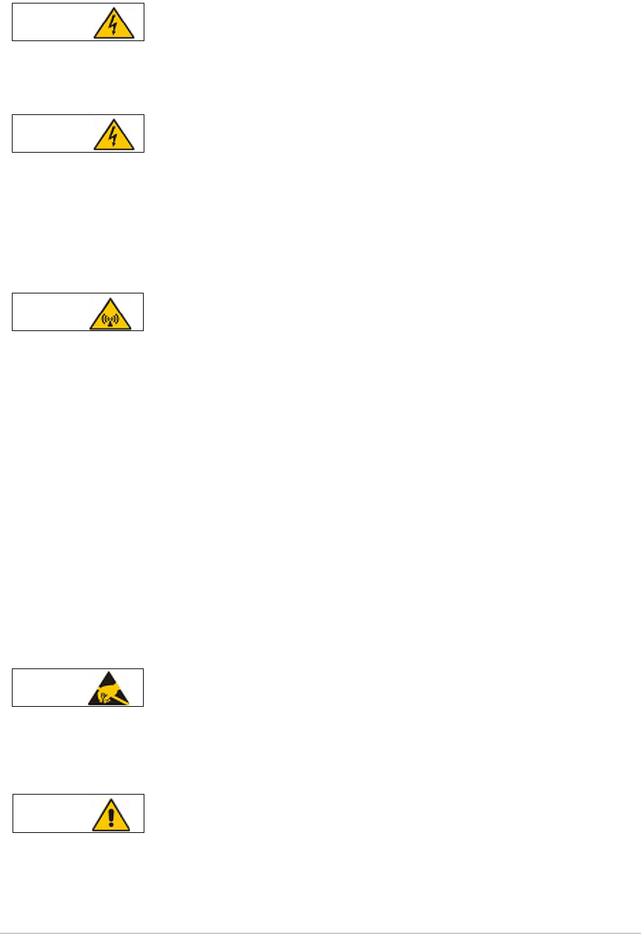
T6T 300 Watt VHF Transmitter Page 68 Installation
Warnings and Cautions
The instructions given in this topic involve connecting dangerous voltage to the transmitter
and should be carried out only by suitably qualified personnel.
The equipment is permanently connected to the mains supply when the mains connectors
are attached. Switching the rear panel Supply switch to off does not isolate all internal
circuits from the mains supply. For this reason, a mains isolating switch should be fitted
close to, and easily accessible from, the transmitter's position. The isolation switch should
isolate both live and neutral supplies to the IEC connectors fitted to the drive assembly and
amplifiers, be clearly labelled, and adequately rated to protect the equipment.
The antenna used with the transmitter must be installed such that the resultant radiated field
strength is below 10 W/m² in areas normally accessible to personnel.
The RF field strength from the antenna can be predicted from the equation S=1.4PG/4πR2
[Where S = power density; P = power input to antenna; G = antenna gain; R = distance
to centre of radiation and 1.4 = multiplication factor for average power based on a
modulation index of 90%.]
Based on this formula for a 300 watt transmitter and using a 0 dBi antenna, the predicted safe
distance from the centre of radiation would be approximately 1.8 m for a field strength of 10 W/m2
(1 mW/cm2).
This meets the requirements of Health Canada Safety Code 6 for RF and microwave exposed
workers. For persons not classed as RF and microwave workers and including the general public
the limit is 2 W/m2 (0.2 mW/cm2) which increases the minimum safe distance to 4.1 m.
Further information on calculating the field strengths and power levels can be found in Health
Canada Safety Code 6 'Limits of Human Exposure to Radiofrequency Electromagnetic Fields in the
Frequency Range 3 kHz to 300 GHz', and also in FCC document OET Bulletin 65.
The T6T transmitter's circuitry contains Electrostatic Sensitive Devices (ESDs). Personnel
must be aware of the precautions necessary to prevent damage to such devices. During
installation all precautions necessary to prevent ESD damage must be taken.
Changes or modifications made to this equipment that are not expressly approved by
Park Air, or parties authorized by Park Air, could void the user’s authority to operate the
equipment.
WARNING Dangerous Voltage
WARNING Dangerous Voltage
WARNING Antenna Radiation
Caution ESDs
Caution Unauthorized Modifications

T6T 300 Watt VHF Transmitter Page 69 Installation
Introduction
The procedures necessary to install a transmitter are listed in Table 13. Installation is in two parts: Steps
1 to 9 in Table 13 must be completed irrespective of how the transmitter is to be configured; step 10
provides a selection of different configurations.
.
Table 13 Installation Procedures
Step Procedure Reference
1 Read and understand the warnings and cautions given on page 68.
2 Perform an initial inspection of the transmitter and fit the correct ac input fuse. page 71
3 Fit the drive assembly and amplifiers into an equipment cabinet. page 72
4 Connect the amplifiers to the drive assembly. page 73
5 Fitting and connecting the combiner. page 74
6 Connect the antenna. page 75
7 Connect the chassis stud to the cabinet or system earth. page 77
8 Connect the dc input supply (if required). page 77
9 Connect the ac input supply (if required). page 78
10 Configuring the transmitter for operational use. page 79

T6T 300 Watt VHF Transmitter Page 70 Installation
Fuses and Connectors
The following list details the equipment supply fuses and connectors. Some of the connectors (depending
on your particular configuration) are required during installation.
Table 14 Fuses and Connectors
Component Type Park Air Part Number
Fuses:
AC input fuses, F3 and F4 for 110-240 V input
AC input fuse, F2 for 110-240 V input
T6.3AH, 250V
T3.15AH, 250V
29L01170108S
29C01100102S
DC input fuses, F1 (drive assembly), F1 and F2 (amplifier) 15A size 0 29-01350201
Connectors:
AC supply connectors IEC 20-02030102
DC supply connectors XLR 3-pin 20-01030106
Antenna connector N-type plug 19-01030301
MARC connector 9-way D-type plug Plug: 20-01090100
Cover: 20-09090101
MARC audio RJ48 plug 20K01080100
MARC data RJ48 plug 20K01080100
Facilities connector 15-way D-type plug Plug: 20-01150100
Cover: 20-09150101
HDLC connector RJ48 plug 20K01080100
T1/E1 connector RJ48 plug 20K01080100
Reference connector SMB connector 19C01050300
Microphone/Diagnostics connector 7-pin DIN plug 20-01070101
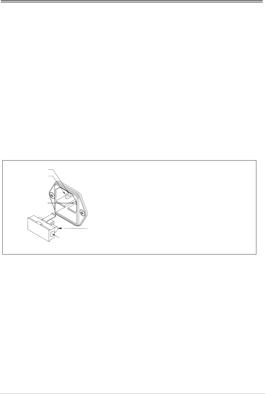
T6T 300 Watt VHF Transmitter Page 71 Installation
Installing the Transmitter
Initial Inspection of the Transmitter
The transmitter comprises:
❑One T6T VHF drive assembly
❑Three T6T VHF amplifiers
❑One T6T VHF combiner
❑One phasing harness.
On receipt of the transmitter, remove all transit packaging and check that there is no damage. If damage
is evident, contact Park Air immediately and retain the original transit packaging.
Fitting the Correct ac Input Fuses
The mains input fuses are an integral part of the rear panel ac connectors. The fuse type must be correct
for the local mains supply as detailed in Fig 11.
❑The drive assembly has one fuse, F2
❑Each amplifier has two fuses, F3 and F4.
Fig 11 ac Input Fuses
FS2
Spare Fuse
Line
Neutral
Earth For a mains input in the range 110 to 240 Vac, fuses F3 and
F4 should be rated T6.3AH, 250V.
For a mains input in the range 110 to 240 Vac, fuse F2
should be rated T3.15AH, 250V.
F3 and F4 (amplifier)
Holder for spare
fuse (not supplied)
F2 (drive assembly)
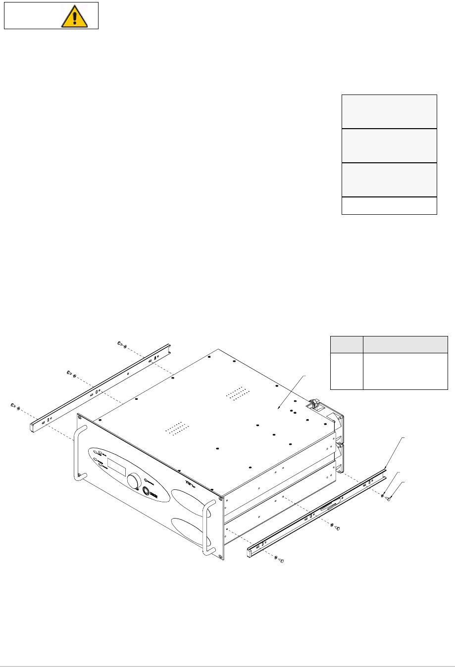
T6T 300 Watt VHF Transmitter Page 72 Installation
Fitting the Drive Assembly and Amplifiers into an Equipment Cabinet
It is essential that the chosen mechanical installation provides adequate support along the
depth (front to rear) of the unit. The transmitter must not be supported by the front panel;
doing so can cause damage.
The drive assembly and amplifiers can be installed on telescopic slides, or on fixed runners, within a
standard 483 mm (19 inch) equipment cabinet. M4 tapped holes, each 10 mm deep (see Fig 12) are
provided on each side of the equipment to accept the slides. Details of suitable telescopic slides and fixed
runners are available from Park Air. Slide fittings (in this case for an amplifier) are shown in Fig 12.
When fitted in the cabinet, the units’ front panels must be secured to the cabinet’s chassis using four
M6 x 16 mm screws and plastic washers.
Fig 12 Slide Fittings
Caution Mechanical Support
Drive Assembly (2 U)
Amplifier 1 (4 U)
Amplifier 2 (4 U)
Amplifier 3 (4 U)
The drive assembly and the three associated amplifiers, which occupy
14 U of cabinet space, should be installed in an equipment cabinet in
the order shown here.
The amplifiers are identical and are designated by the numbers 1, 2 and
3 for connection purposes only.
3
4
2
1
M4 x 8 mm Half Head Bolt
M4 Wavy Washer
Inner Slide
Transmitter
Description
4
3
2
1
Item
Item Description
1
2
3
4
Amplifier
Inner slide
M4 wavy washer
M4 x 8 mm half-head bolt
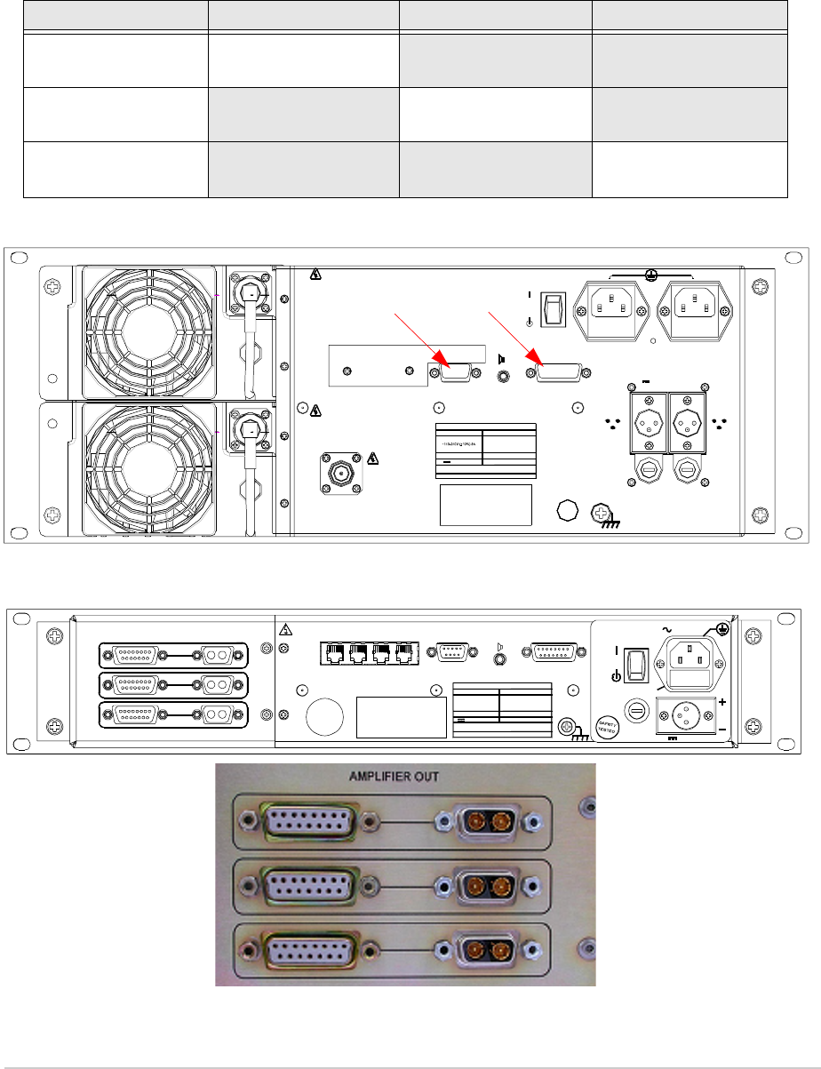
T6T 300 Watt VHF Transmitter Page 73 Installation
Connecting the Amplifiers to the Drive Assembly
Having fitted the drive assembly and amplifiers into a cabinet, the units must be interconnected, as
shown in Fig 17, using the supplied phasing harness, part number 17L13000006. The connections that
must be made are listed in Table 15. Fig 13 shows the amplifier rear panel connectors CN5 and CN8.
Fig 14 shows the drive assembly rear panel and Amplifier Out connectors.
Fig 13 100 Watt Amplifier Rear Panel Showing CN5 and CN8
Fig 14 Drive Assembly Rear Panel Showing Amplifier Out Connectors
Table 15 Amplifier/Drive Assembly Interconnections
Drive Assembly Amplifier 1 Amplifier 2 Amplifier 3
CN1
CN4
CN8
CN5
CN2
CN5
CN8
CN5
CN3
CN6
CN8
CN5
BEFORE
CONNECT
RF VOLT AGES
DANGER HIGH
USE
CONNECT
BEFORE
USE
RF VOLT AGES
DANGER HIGH
SUPPLY
FACILITIES FUSE F3 FUSE F4
~ AC SUPPLIES
DC SUPPLIES
-
+
-
+
FUSE F1 FUSE F2
48-62 Hz
AC SUPPLY
P OW ER 800VA max
RATINGS
21.6-32V 28 A
CONNECTIN G SUPP LIES
DC SUPPLY
DIS CONNECT SUPP LIES WH EN NOT IN USE
SEE INS TA LLATION INST RUCTIONS BEFORE
FUSE F3 / F4
FUSE F1 / F2
110- 120V T 4A 12 5V UL
110-2 40V T 4A 250V IEC
F15A 3 2V
USE
BEFO RE
ANTENNA
CONNECT
ANTENNA
DANGER HIGH
RF V OLTAG ES
CN8 CN5
AMPLIFIER OUT ANTENNA
DANGER HIGH
RF VOLTAGES
CONNECT
ANTENNA
BEFORE
USE
T1/E1 HDLC MARC
DATA MARC
AUDIO MARC FACILITIES
21. 6 - 32V 10A
POWE R 400VA m ax
~ 110 - 240V ( +10%) 4A
SEE INSTALLATION INSTRUCTIONS BEFORE
CONNECTING SUPPLIES
DI SCO NN EC T SU PP LI ES WHE N NOT IN U S E
DC SUPPLY
AC SUPPLY
48 - 62 Hz
FUSE F1
F15A 32V
110V - 120V T 4A 125V UL
110-24 0V T4A 25 0V IEC
RATINGS
FUSE F2
DC SUPPLY
FUSE F2
FUSE F1
SUPPLY
AC SUPPLY
CN6
CN5
CN4
CN3
CN2
CN1
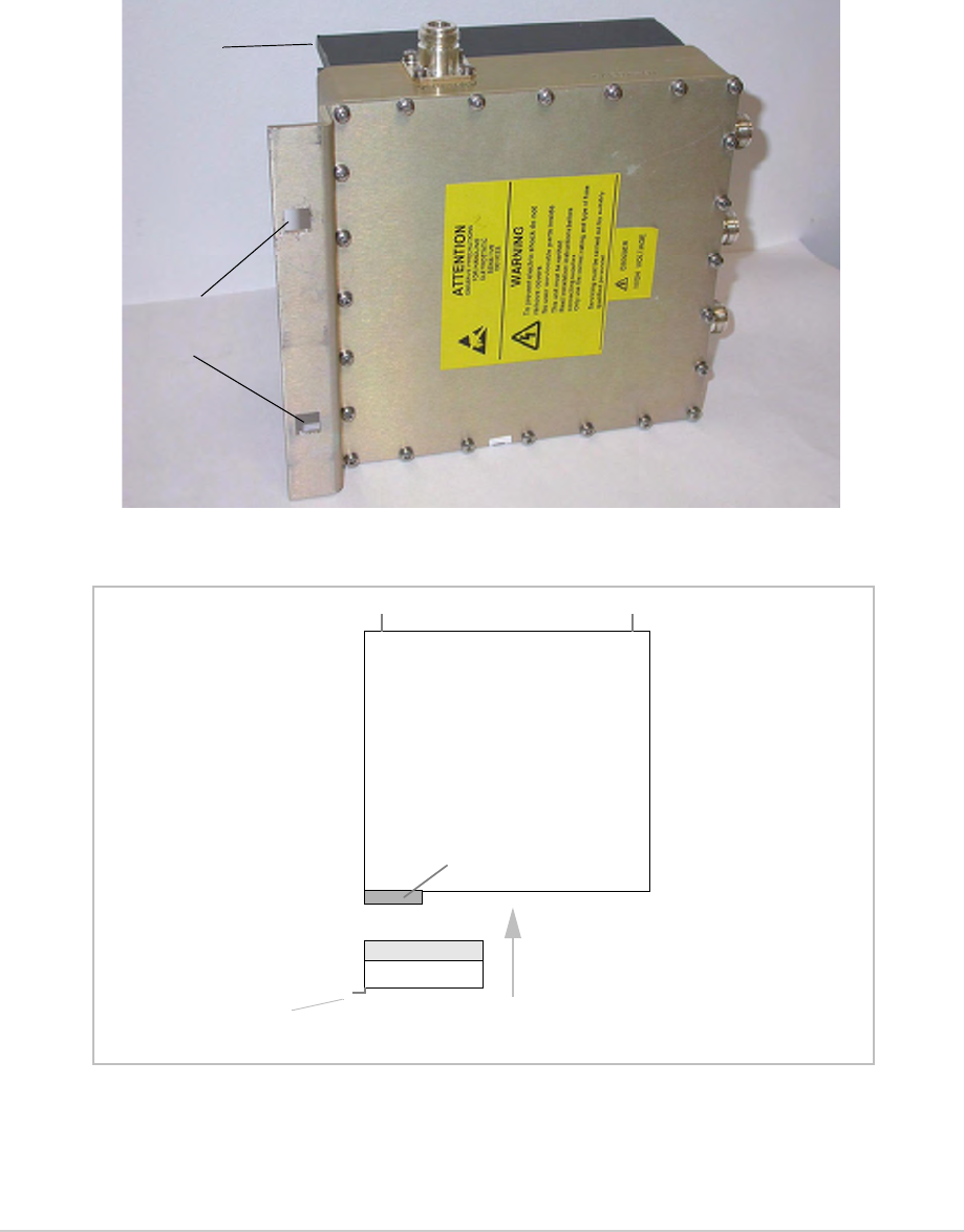
T6T 300 Watt VHF Transmitter Page 74 Installation
Fitting and Connecting the Combiner
Fitting
The combiner, shown in Fig 15, should be mounted at the back of the cabinet directly behind the
amplifiers’ fans and with the heatsink pointing into the cabinet. Cabinet mounting holes are provided in
the combiner’s bracket to allow fixing to a cabinet upright. Fig 16 shows a plan view of the mounting
arrangement.
Fig 15 Combiner
Fig 16 Combiner Mounting Arrangement Plan View
Cabinet
Mounting Holes
Heatsink
Amplifier
Fans
Combiner
Heatsink
Front of Cabinet
Airflow
Bracket fits to upright
at rear of cabinet

T6T 300 Watt VHF Transmitter Page 75 Installation
Connecting
A coaxial cable connects each amplifier to the combiner’s three inputs (marked IN) as shown in Fig 17.
These cables are part of the phasing harness, part number 17L13000006.
The cables used to connect from the amplifiers to the combiner are critical length. Use only
the cables supplied by Park Air.
Connecting the Antenna
The combiner’s antenna connector is an N-type socket suitable for connecting a 50 ohm antenna.
The antenna used with the transmitter must be installed such that the resultant radiated field
strength is below 10 W/m² in areas normally accessible to personnel.
The RF field strength from the antenna can be predicted from the equation S=1.4PG/4πR2
[Where S = power density; P = power input to antenna; G = antenna gain; R = distance
to centre of radiation and 1.4 = multiplication factor for average power based on a
modulation index of 90%.]
Based on this formula for a 300 watt transmitter and using a 0 dBi antenna, the predicted safe
distance from the centre of radiation would be approximately 1.8 m for a field strength of 10 W/m2
(1 mW/cm2).
This meets the requirements of Health Canada Safety Code 6 for RF and microwave exposed
workers. For persons not classed as RF and microwave workers and including the general public
the limit is 2 W/m2 (0.2 mW/cm2) which increases the minimum safe distance to 4.1 m.
Further information on calculating the field strengths and power levels can be found in Health
Canada Safety Code 6 'Limits of Human Exposure to Radiofrequency Electromagnetic Fields in the
Frequency Range 3 kHz to 300 GHz', and also in FCC document OET Bulletin 65.
Caution Critical Length Cables
WARNING Antenna Radiation
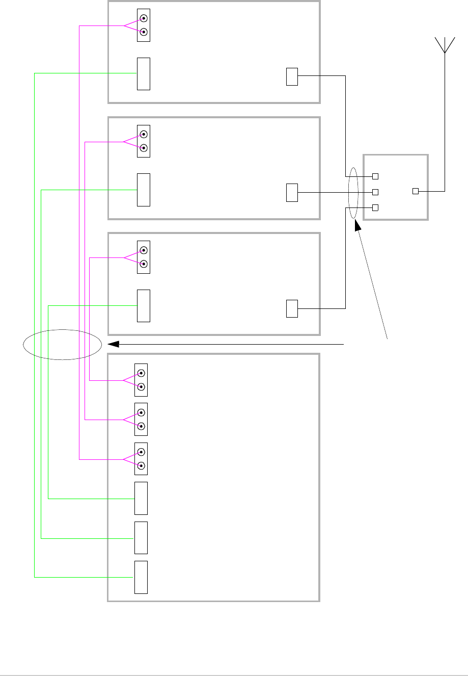
T6T 300 Watt VHF Transmitter Page 76 Installation
Fig 17 300 Watt Transmitter Interconnections
Amplifier 1
CN8
CN5 Antenna
Drive Assembly
Facilities
Amplifier 2
CN8
CN5 Antenna
Facilities
Amplifier 3
CN8
CN5 Antenna
Facilities
CN3
CN2
CN1
CN6
CN5
CN4
Combiner
1
2
3Ant
Antenna
Phasing Harness
(17L13000006)
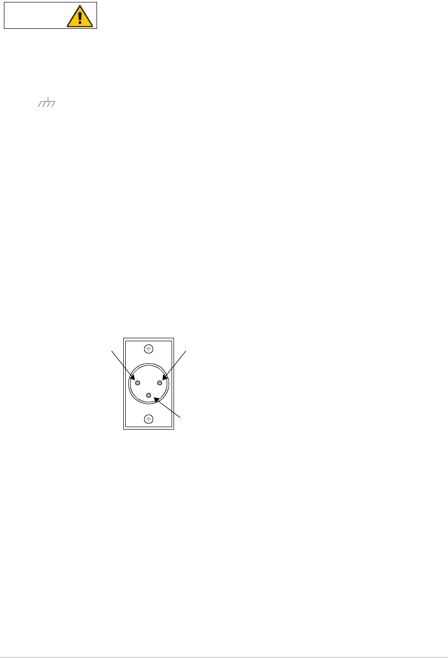
T6T 300 Watt VHF Transmitter Page 77 Installation
Connecting the Chassis Stud
A chassis stud is fitted to each amplifier’s rear panel and to the drive assembly. This stud is
used to connect the equipment to the equipment cabinet, or to the user's system earth point.
The stud must not be used as the safety earth.
In order not to compromise the transmitter’s Electromagnetic Compatibility (EMC) the chassis stud,
marked and fitted to the rear panel must be connected to the equipment cabinet (if a cabinet is being
used) or to the user's system earth point. The connection should be made using a single tri-rated, green-
and-yellow cable having a cross-sectional area of 2.5 mm2. The cable should have CSA and UL1015
approval, and be connected to the chassis stud through an M6 eyelet (for example, Park Air part number
20-08010103).
Failure to comply with this instruction could result in non-compliance with the European
Commission EMC Directive 89/336/EEC.
Connecting the DC Input Supply
The transmitter operates from either an ac, or a dc input supply. When both ac and dc are connected,
operation from the ac supply takes priority; automatic change-over to the dc supply occurs if the ac
supply fails. On restoration of the ac supply, the equipment reverts to ac operation.
Two dc input supply connectors (see Fig 18) are used on each amplifier and one on the drive assembly.
The recommended minimum rating of the dc supply cables is: 2-core having a cross-sectional area of
1.5 mm2 per core. The supply cables should be fitted with XLR 3-pin connectors (Park Air part number
20-01030106).
Fig 18 DC Connectors
WARNING Chassis Earth
Positive Negative
Not used
Pin-out of DC connector looking
into the mating face of the chassis
mounted socket.
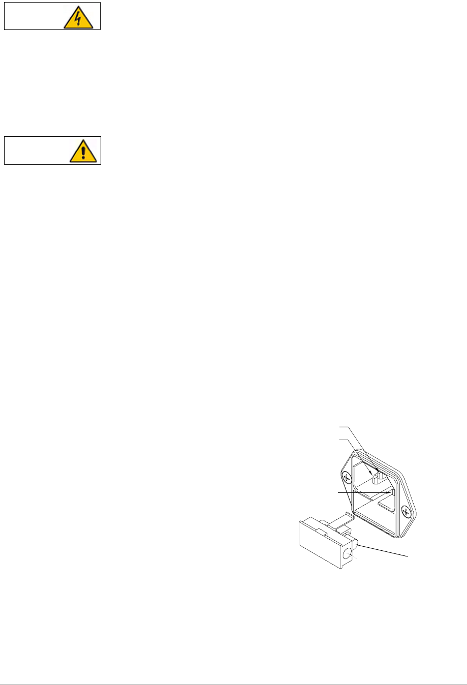
T6T 300 Watt VHF Transmitter Page 78 Installation
Connecting the AC Input Supply
The equipment is permanently connected to the mains supply when the mains connectors
are attached. Switching the rear panel Supply switch to off does not isolate all internal
circuits from the mains supply. For this reason, a mains isolating switch should be fitted
close to, and easily accessible from, the transmitter's position. The isolation switch should
isolate both live and neutral supplies to the IEC connectors fitted to the drive assembly and
amplifiers, be clearly labelled, and adequately rated to protect the equipment.
This equipment must be earthed. The earth terminal of the ac connector should be used as
the safety earth.
Two ac input connectors are fitted to each amplifier rear panel, and one to the drive unit rear panel. The
cables used to connect between the equipment and the ac power source should be 3-core (to IEC 227)
rated 250 Vac at 8 amps, and have a minimum cross-sectional area of 1.0 mm2 per core. Park Air
recommends the use of polyvinyl chloride (PVC) insulated cable. The cable must be fitted with the IEC
approved equipment connector and conform to the following specification:
❑If PVC insulated, be not lighter than ordinary polyvinyl chloride sheathed flexible cord according
to IEC publication 227 (designation H05 VV-F, or H05 VVH2-F)
❑If rubber insulated, be of synthetic rubber and not lighter than ordinary tough rubber-sheathed
flexible cord according to IEC publication 245 titled ‘Rubber Insulated Cables of Rated Voltages
up to and Including 450/750 V (designation H05 RR-F)’.
The T6T 300 W transmitter is a Class 1 equipment. The ac supply cables should have a green-and-
yellow protective earthing conductor electrically connected to the protective earthing terminal of the
equipment connector and the mains plug. Park Air recommends the ac supply cable is colour coded in
accordance with the electrical appliance (colour code) regulations for the UK. That is:
WARNING Dangerous Voltage
WARNING Earth Connection
FS2
Spare
Line
Neutral
Earth
❑The core coloured green-and-yellow must be
connected to the terminal in the plug that is
marked with the letter E or by the earth symbol
or coloured green-and-yellow
❑The core coloured blue must be connected to
the terminal that is marked with the letter N or
coloured black
❑The core coloured brown must be connected to
the terminal that is marked with the letter L or
coloured red.
Fuse