Park Air Systems B63100HS VHF Ground to air transmitter User Manual
Park Air Systems Limited VHF Ground to air transmitter Users Manual
User manual
T6T VHF 100 W Transmitter
User Documentation

Page ii T6T VHF 100 W Transmitter
Handbook Title: T6T VHF 100 W Transmitter User Documentation
Handbook Part Number: 31-3T6T100V
Handbook Version: 2.0
Date of Issue: February 2005
Equipment Modification Level 7
Published By: Park Air Systems
Northfields
Market Deeping
Peterborough PE6 8UE
England
Telephone: From UK, 01778 345434
From outside UK, 44 1778 345434
Fax: From UK, 01778 342877
From outside UK, 44 1778 342877
www.parkairsystems.com
Errata
Any errors found in this handbook are promulgated through the Park Air FTP network. Any
user can access this information by logging on to:
ftp.parkairsystems.com
When logged on, select the public (Pub) folder, then the Handbook Errata Sheets folder,
and then select the required equipment model.
[Adobe Acrobat™ must be loaded on your PC to use this facility]
T6T VHF 100 W Transmitter Page iii
Health and Safety
Warnings
A warning is used to indicate possible danger to personnel. Throughout Park Air handbooks, warnings
are indicated by the following symbols:
Cautions
A caution is used to indicate possible danger to the equipment.
Trademarks
The following tradenames are used in this handbook.
IBM This is a registered trademark of International Business Machines.
Microsoft This is a registered trademark of Microsoft Corporation in the USA and other
countries.
Windows This is a registered trademark of Microsoft Corporation in the USA and other
countries.
Indicates electrical danger to personnel.WARNING
Indicates a hazardous material.
WARNING
Indicates a non-ionizing radiation hazard.
WARNING
Indicates a specified danger to personnel.
WARNING
Indicates the presence of electrostatic sensitive devices (ESSD). Caution
Indicates a specified danger to the equipment. Caution

Page iv T6T VHF 100 W Transmitter
List of Abbreviations
ac alternating current
AGC automatic gain control
AM amplitude modulation
ATC air traffic control
BER bit error rate
BIT built-in test
C celsius
CD compact disk
dB decibel
dc direct current
DSB double sideband
E-BIT external bit signal
ESSD electrostatic sensitive devices
Fig figure
FM frequency modulation
Hz hertz
IF intermediate frequency
kg kilogramme
kHz kilohertz
LCD liquid crystal display
mmetre
mA milliamp
MARC multi-access remote control
mm millimetre
mW milliwatt
MHz megahertz
MSK minimum shift keying
PA power amplifier
PC personal computer
PCB printed circuit board
pk-pk peak-to-peak
ppm parts per million
PSU power supply unit
PTT press to transmit
RF radio frequency
ROM read-only memory
RSE2 remote site equipment
RSSI receiver signal strength indication
Vvolt
VFP virtual front panel
VHF very high frequency
VOGAD voice-operated gain adjusting device
VSWR voltage standing wave ratio
Wwatt
Approvals and Standards T6T VHF 100 Watt Transmitters
Approvals:
The equipment is designed to meet the essential requirements of Directives
1999/5/EC, 89/336EEC as amended by Directive 93/68/EEC, and 72/23/EEC.
Standards:
The following standards are applied:
EMC EN 301 489-1; EN 301 489-22.
Health & Safety, EN 60950, CAN/CSA-C22.2 No. 60950, UL 60950.
Radio EN 300 676, IC RSS141, FCC part 15 and 87.
Telecom CS-03.
FCC Statement:
This device has been tested and found to comply with the limits for a Class B digital
device, pursuant to part 15 of the FCC Rules. These limits are designed to provide
reasonable protection against harmful interference in a residential installation.
This equipment generates, uses and can radiate radio frequency energy and, if not
installed and used in accordance with the instructions, may cause harmful
interference to radio communications. However, there is no guarantee that
interference will not occur in a particular installation.
If this equipment does cause harmful interference to radio or television reception,
which can be determined by turning the equipment off and on, the user is
encouraged to try to correct the interference by one or more of the following
measures:
-Reorient or relocate the receiving antenna.
-Increase the separation between the equipment and the receiver.
-Connect the equipment into an outlet on a circuit different from that to which the
receiver is connected.
-Consult the supplier or an experienced radio/TV technician for help.
Operation on 8.33 kHz channel spacing is restricted to European customers.
This Class B digital apparatus complies with Canadian ICES-003

Page vi T6T VHF 100 W Transmitter
About This Hard Copy
This document, apart from the preface, is a hard copy of the files contained on the CD and comprises
the following parts:
Preface (not on CD)
Introduction
Specification
Operation
Installation
Maintenance.

Back to Transmitter
Main Page
Introduction
This topic gives a brief introduction to the T6T VHF 100 W Multimode Transmitter.
T6T VHF 100 W Transmitter Page 2 Introduction
Back to Transmitter
Main Page
Purpose
The T6T VHF multimode 100 W transmitter is intended for use in fixed ground environments such as
airports and en-route centres. The transmitter operates in voice and ICAO defined data modes at
frequencies between 118 and 136.975 MHz.
Dependent on the software loaded into the radio, the following operating modes can be selected:
❑AM-Voice. All transmitters have this mode
❑AM-MSK (optional)
❑Mode 2 (optional)
❑Mode 3 (optional).
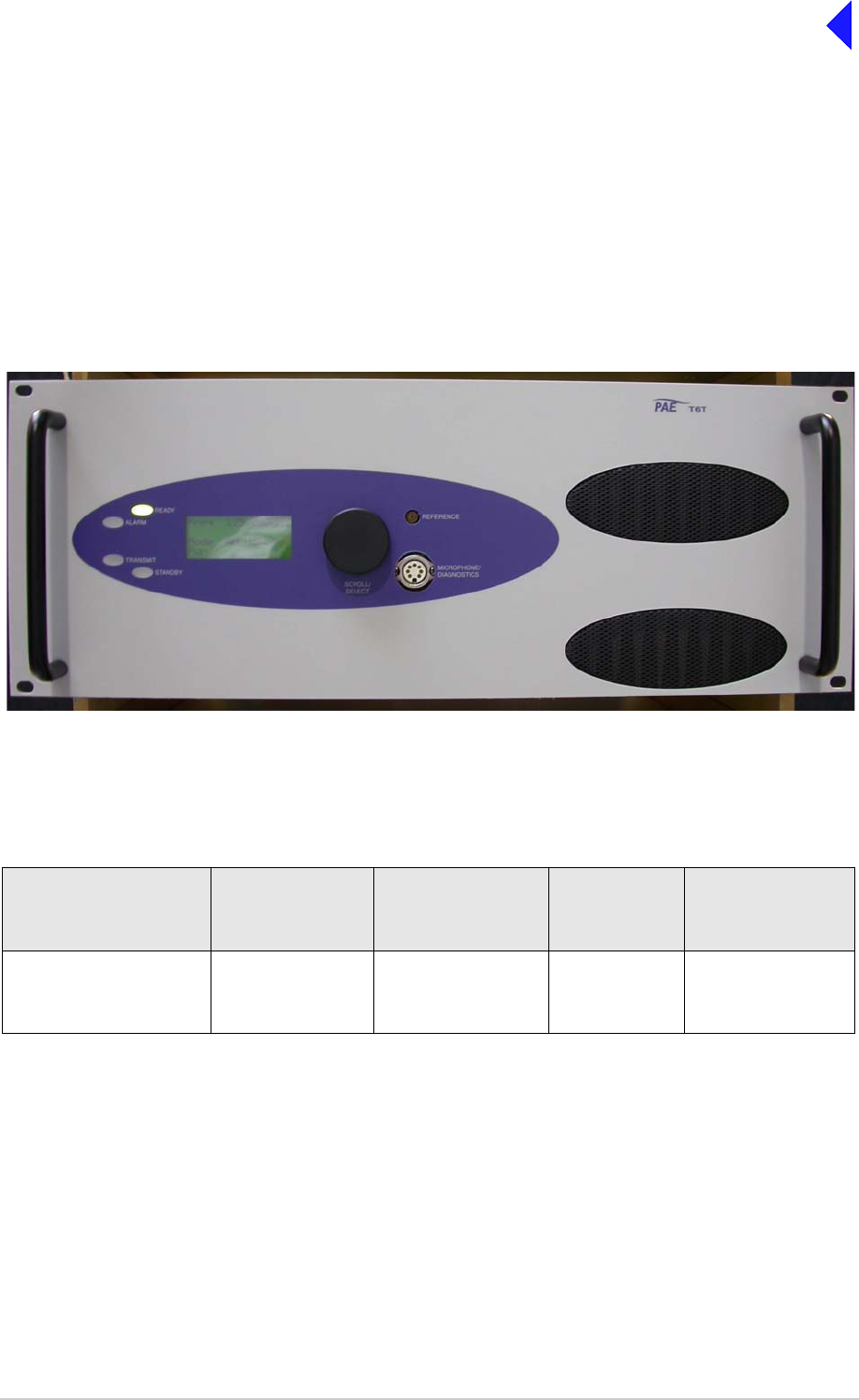
Fig 1 T6T VHF 100 W Transmitter
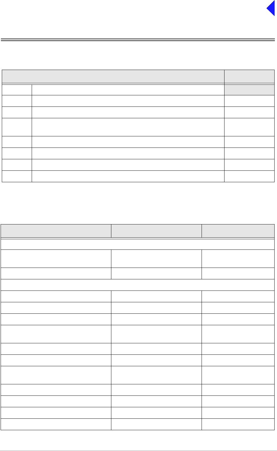
Models and Part Numbers
The following table identifies the T6T VHF 100 W transmitters:
Mechanical Installation
The transmitter fits into an industrial standard 19 inch (483 mm) equipment cabinet and occupies 4U of
space.
Description Part Number Frequency Range Channel
Spacing
(AM-Voice)
Special
Applications
T6T 100 W standard
frequency coverage high
stability transmitter
B63100HS/NB 118 to 136.975 MHz 25 kHz or
8.33 kHz Supports 5-offset
carrier operation
T6T VHF 100 W Transmitter Page 3 Introduction
Back to Transmitter
Main Page
Frequency Selection
T6 radios operate with 8.33 kHz and 25 kHz channel spacing. The radios recognize frequencies entered
in ICAO format and automatically adjust to the correct channel spacing. For multichannel operation up
to 100 preset frequency channels can be stored in the radio for immediate recall; any combination of
8.33 kHz and 25 kHz channel spacing can be stored. Any valid operating frequency can be selected from
the radio’s front panel or a compatible remote control equipment.
Operating Parameters
The transmitter’s operating parameters are set using the front panel multi-purpose Scroll/Select switch,
or by using the Park Air Virtual Front Panel (VFP) software in conjunction with a Personal Computer (PC).
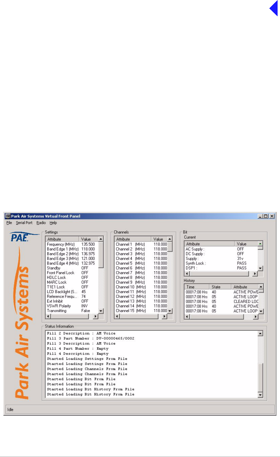
Virtual Front Panel
The Virtual Front Panel (VFP) software supplied on CD with the radio is compatible with any PC or laptop
running Windows 2000™ or Windows XP™. The VFP allows changes to a radio’s settings and channel
information, it displays the current BIT state, displays BIT history, allows security locks to be set, and
provides maintenance facilities. A typical VFP presentation is shown in Fig 2. Using the VFP has several
advantages over setting a radio from the front panel; these are:
❑A profile of the operational settings and channel information can be created, stored on disk, and
then recalled to download into other radios.
❑A print out of the radio’s profile can be made from the VFP.
❑The front panel controls can be locked. Front Panel Lock is available only when using the VFP.
Fig 2 Typical VFP Presentation

Back to Transmitter
Main Page
Intentionally Blank

Back to Transmitter
Main Page
Specification
This section gives the specification applicable to the T6T VHF 100 W Multimode Transmitter
operating in AM modes, Mode 2 and Mode 3.
All radios operate in AM-Voice mode. Additional software must be loaded to allow AM-MSK,
Mode 2 and Mode 3 operation.

T6T VHF 100 W Transmitter Page 2 Specification
Back to Transmitter
Main Page
General Specification
The general specification applies to the T6T 100 watt transmitter irrespective of the selected operating
mode. Separate listings are given for AM modes, Mode 2 and Mode 3. One model of the T6T VHF 100 W
Multimode Transmitter is available as detailed in Table 1.
Frequency accuracy
The frequency accuracy is better than 0.3 ppm.
Number of Channels
The transmitter has a multichannel capability. 100 channels can be stored and recalled.
Power Requirements
The transmitter operates from an ac mains supply, or a dc input supply. When both supplies are
connected, the dc input acts as an automatic backup for the ac mains.
ac input supply The transmitter operates from a 48 to 62 Hz single-phase ac supply
and automatically adjusts to operate from any supply voltage ranging
from 110 Vac to 230 Vac ±10%. The power consumption figures are
given in Table 2.
dc input supply The transmitter operates from a dc input supply between 21.6 and
32 V (measured at the radio’s input). Current loading is given in
Table 2.
Table 1 100 Watt T6 Transmitter
Description Part Number Frequency Range Special Applications
100 watt, high stability, standard
frequency coverage transmitter B63100HS/NB 118 to 136.975 MHz Supports 5-offset carrier
operation
Table 2 Power Consumption
Requirement 100 Watt Transmitter Normal Operation
ac dc
Maximum 1000 VA 24 A
Typical 600 VA 17 A
Not Transmitting 90 VA 1.5 A

T6T VHF 100 W Transmitter Page 3 Specification
Back to Transmitter
Main Page
Dimensions and Weight
The dimensions and weight of the 100 watt transmitter are:
Width 483 mm (19 inches).
Height 177.8 mm (7 inches). The height occupies 4U of equipment cabinet
space.
Depth 430 mm (16.9 inches) measured from front panel to rear panel.
465 mm (18.3 inches) measured from front panel to rear RF
connectors.
Weight 25 kg (55 pounds).
Environmental
Temperature range The transmitter operates to specification across the temperature
range of -20°C to +55°C.
The transmitter can be stored at temperatures ranging from
-30°C to +70°C without causing any damage.
Humidity The transmitter operates to specification at a relative humidity
between 5% and 90% non-condensing.
Altitude The transmitter operates to specification up to 15,000 feet.
Additionally it is capable of storage at altitudes up to 50,000 feet
without damage.
Shock and vibration The transmitter complies with shock and vibration protection
MIL-STD-810E, method 516.4, procedure VI - Bench Handling.
Ventilation The transmitter is cooled by integral fans, which normally runs at half
speed. At an RF PA temperature of 45°C this is increased to full speed
and at 40°C it reduces to half speed again.
The transmitter power supply units also use internal fans.
Warm up time The transmitter is fully operational within 20 seconds but can take up
to 10 minutes to achieve frequency accuracy for offset carrier.

T6T VHF 100 W Transmitter Page 4 Specification
Back to Transmitter
Main Page
AM Modes
The transmitter can operate in AM-Voice mode (standard) and AM-MSK mode (optional). The following
specifications apply to both modes unless stated otherwise.
Transmitter RF Characteristics
RF Power Output
The RF carrier output power is adjustable in 2 W steps from 10 W to 100 W.As an option, the maximum
selectable power can be limited. Output power is automatically controlled under the following conditions:
Frequency range Variations in power remain within 0 to +1 dB over the operational
frequency range.
Low supply voltage Variations in power remain within ±1 dB for supply voltages between
24 Vdc and 32 Vdc.
High VSWR Loop error can reduce power progressively by up to 3 dB. Variations
in power remain within ±1 dB into a VSWR of up to 2.5:1. At a VSWR
greater than this the output power may be reduced by 10 dB ±1 dB.
High RF PA temperature If the RF PA temperature sensor exceeds 80°C the output power is
reduced by 3 dB ±1 dB. If the RF PA temperature sensor exceeds
90°C the transmitter is de-keyed and automatically re-keyed at 70°C.
PA Module Failure If one of the two PA modules fails, the transmitter will continue to
operate at half power, 50 watts.
Duty Cycle
Both modes 100% continuous operation.
Channel Spacing
AM-Voice mode The transmitter is capable of both 25 kHz channel spacing and
8.33 kHz channel spacing.
AM-MSK mode 25 kHz.
Offset Carrier
AM-Voice mode The transmitter is capable of offsetting the carrier frequency to provide
2, 3, 4 and 5-carrier offset.
AM-MSK mode Offset carrier is not available.
Harmonic Outputs
Both modes Second harmonic outputs are less than -36 dBm, third harmonic
outputs are less than -46 dBm and fourth harmonic outputs and above
up to 4 GHz, are less than -56 dBm.

T6T VHF 100 W Transmitter Page 5 Specification
Back to Transmitter
Main Page
Spurious Outputs
Both modes The spurious outputs are less than -46 dBm for modulation depths up
to 90%, measured at greater than 500 kHz from carrier in the
frequency range 9 kHz to 4 GHz. There are no coherent spurious
outputs above the spectral mask at less than 500 kHz.
Intermodulation
Both modes Intermodulation products, caused by an interfering signal with the
same power as the transmitter isolated by 30 dB, are at least -40 dBc
at ≥±150 kHz and -50 dBc at ≥±500 kHz.
Transmitter Modulation Characteristics
The transmitter modulation characteristics are as follows:
Mode
AM-Voice AM-Voice mode uses Double Sideband (DSB) Amplitude Modulation
(AM) full carrier; emission designator 6K80A3EJN for 25 kHz
channels and 5K00A3EJN for 8.33 kHz channels.
AM-MSK AM-MSK mode uses Double Sideband (DSB) Amplitude Modulation
(AM) full carrier; emission designator 13K0A2DJN.
Modulation Depth
Both modes The transmitter is capable of modulation depths up to 95%.
Hum and Noise
Both modes The hum and noise is more than 45 dB below the signal level for line
input levels <-13 dBm, and more than 50 dB below the signal level for
line input levels ≥-13 dBm, for a carrier modulated by a 1 kHz signal
with a modulation depth of 90%.
Frequency Response
25 kHz channel spacing AM-Voice and AM-MSK: The variation in frequency response with
reference to a 1 kHz signal is within +0.5 dB and -1.5 dB across the
frequency range 300 to 3400 Hz. The response is also less than
-20 dB at 100 Hz and below, and less than -30 dB at 4 kHz and above.
8.33 kHz channel spacing AM-Voice only: The variation in frequency response with reference to
a 1 kHz signal is within +0.5 dB and -1.5 dB across the frequency
range 350 Hz to 2500 Hz. The response is also less than -10 dB at
100 Hz and below, and less than -30 dB at 3200 Hz and above.
Distortion
25 kHz channel spacing The total harmonic distortion is less than 5% due to signals with a
modulation depth of 90%, within the frequency range 300 Hz to
3400 Hz.
8.33 kHz channel spacing AM-Voice only: The total harmonic distortion is less than 5% due to
signals with a modulation depth of 90%, within the frequency range
350 Hz to 2500 Hz.

T6T VHF 100 W Transmitter Page 6 Specification
Back to Transmitter
Main Page
Residual FM
Both modes For a test signal of 1 kHz set at 80% modulation depth applied to the
line input of the transmitter, the unwanted peak frequency modulation
does not exceed ±500 Hz.
VOGAD
AM-Voice The VOGAD has an operational range of 30 dB. The VOGAD can be
disabled.
AM-MSK The VOGAD is disabled.
Mute
AM-Voice The mute level is set at 15 dB below the average speech line level
setting. The mute can be disabled.
AM-MSK The mute is disabled.
Differential Group Delay
AM-MSK There is less than 60 µs differential group delay for signals in the
range 1200 to 2400 Hz.
Transmitter Control
Transmitter control characteristics are as follows:
Audio Inputs
Voice can be connected to the transmitter via the front panel microphone connector. Voice can also be
connected via the line inputs. Line level setting from -30 to +10 dBm.
PTT Time Out
The time out period is adjustable from 2 to 510 seconds in 2 second steps or it can be disabled.

T6T VHF 100 W Transmitter Page 7 Specification
Back to Transmitter
Main Page
Mode 2
This section gives the transmitter specification applicable to Mode 2 operation. Mode 2 parameters are
identical to AM-Voice mode parameters with the following exceptions:
RF Power Rise Time
The transmitter produces more than 90% of full power output within the first 2 symbols of the power
stabilization segment, which is the first segment of the training sequence and consists of 4 symbols each
representing 000.
RF Power Decay Time
The output power decays by more than 20 dB within 2.5 symbols of the middle of the final symbol.
Channel Spacing
25 kHz channel spacing only.
Transmitter Modulation Characteristics
Mode 2 uses Carrier Sense Multiple Access (CSMA) differentially encoded 8-phase shift keying
(D8PSK), using a raised cosine filter with α=0.6 (nominal value), emission designator 14K0G1DE.
Information is differentially encoded with 3 bits per symbol transmitted as changes in phase rather than
absolute phase. The data stream is divided into groups of 3 consecutive data bits, least significant bit
first. Zeros are padded to the end of transmissions if needed for the final channel symbol.
Modulation Rate
The symbol rate is 10,500 symbols/second (±0.005%), resulting in a nominal bit rate of 31,500 bits/s.
RMS Phase Error
The RMS phase error is less than 3°. The error vector magnitude is less than 6%.
Phase Acceleration
The total frequency change during the transmission of the unique word is less than 10 Hz. After this, the
phase acceleration is less than 500 Hz/s.

T6T VHF 100 W Transmitter Page 8 Specification
Back to Transmitter
Main Page
Mode 3
This section gives the transmitter specification applicable to Mode 3 operation. Mode 3 parameters are
identical to AM-Voice mode parameters with the following exceptions:
RF Power Rise Time
The transmitter produces more than 90% of full power output within the first 2 symbols of the power
stabilization segment, which is the first segment of the training sequence and consists of 4 symbols each
representing 000.
RF Power Decay Time
The output power decays by more than 20 dB within 2.5 symbols of the middle of the final symbol.
Channel Spacing
25 kHz channel spacing only.
Transmitter Modulation Characteristics
Mode 3 uses Time Division Multiple Access (TDMA) differentially encoded 8-phase shift keying (D8PSK),
using a raised cosine filter with α=0.6 (nominal value), emission designator 14K0G7WET. Information is
differentially encoded with 3 bits per symbol transmitted as changes in phase rather than absolute phase.
The data stream is divided into groups of 3 consecutive data bits, least significant bit first. Zeros are
padded to the end of transmissions if needed for the final channel symbol.
Modulation Rate
The symbol rate is 10,500 symbols/second (±0.005%), resulting in a nominal bit rate of 31,500 bits/s.
RMS Phase Error
The RMS phase error is less than 3°. The error vector magnitude is less than 6%.
Phase Acceleration
The total frequency change during the transmission of the unique word is less than 10 Hz. After this, the
phase acceleration is less than 500 Hz/s.

Back to Transmitter
Main Page
Operation
This topic describes the transmitter’s operating controls and indicators.
It also details how to set up the transmitter’s operating parameters.

T6T VHF 100 W Transmitter Page 2 Operation
Back to Transmitter
Main Page
Controls, Indicators and Front Panel Connectors
This section describes the transmitter’s controls, indicators and front panel connectors.
Front Panel
The transmitter’s front panel is illustrated below.
Scroll/Select Switch and LCD
The Scroll/Select switch is used in conjunction with the LCD to select most of the transmitter's operational
settings. During normal operation, the LCD shows the operating frequency, the channel number (if the
channel store facility is used), the carrier offset (if used), and displays a graphical representation of
instantaneous peak power.
The example LCD screen above shows the transmitter operating on 118.000 MHz; the frequency has
been preset as channel 100 and offset at +7.3 kHz.
Ready Indicator
A green indicator that lights when the transmitter is ready for use and no BIT faults have been detected.
Transmit Indicator
An amber indicator that lights when the transmit circuit is keyed and producing output power.
Alarm Indicator
A red indicator that either flashes, or lights, when a BIT fault has been detected. BIT indications are
classified as either Alarms or Alerts.
If an ‘alert’ condition is detected, the Alarm indicator flashes, the Ready indicator remains lit, and the
transmitter remains operational. A BIT ‘alert’ is indicated if:
❑The transmitter RF output power has reduced from its setting by more than 1 dB but not more than
3 dB.
❑The supply volts falls below a pre-defined level.
Any other BIT condition results in an alarm. When detected, the Alarm indicator lights and the Ready
indicator becomes unlit; the transmitter cannot be used.
READY
ALARM
TRANSMIT
STANDBY SCROLL/
SELECT
MICROPHONE/
DIAGNOSTICS
REFERENCE
F r e q 1 1 8 .0 0 0 M H z
C h 1 0 0 + 7 . 3 k H z
P w r
Scroll/Select SwitchLCD
M o d e A M V o i c e 1
T6T VHF 100 W Transmitter Page 3 Operation
Back to Transmitter
Main Page
Standby Indicator
A red indicator that lights when the transmitter is in standby mode. When in standby mode, most of the
radio's circuits are inactive, the front panel LCD is blanked, and the transmitter cannot be keyed.
Standby mode is selected and deselected using the front panel Scroll/Select switch and LCD, by initiating
an instruction through a MARC system, through a T6 controller or through the VFP. For details of front
panel selection and deselection see page 14.
Reference Connector
An SMB jack socket that allows a frequency counter to monitor the transmitter's reference frequency.
This connector is used only for maintenance purposes. The instructions for checking and adjusting the
reference frequency are given in the Maintenance section.
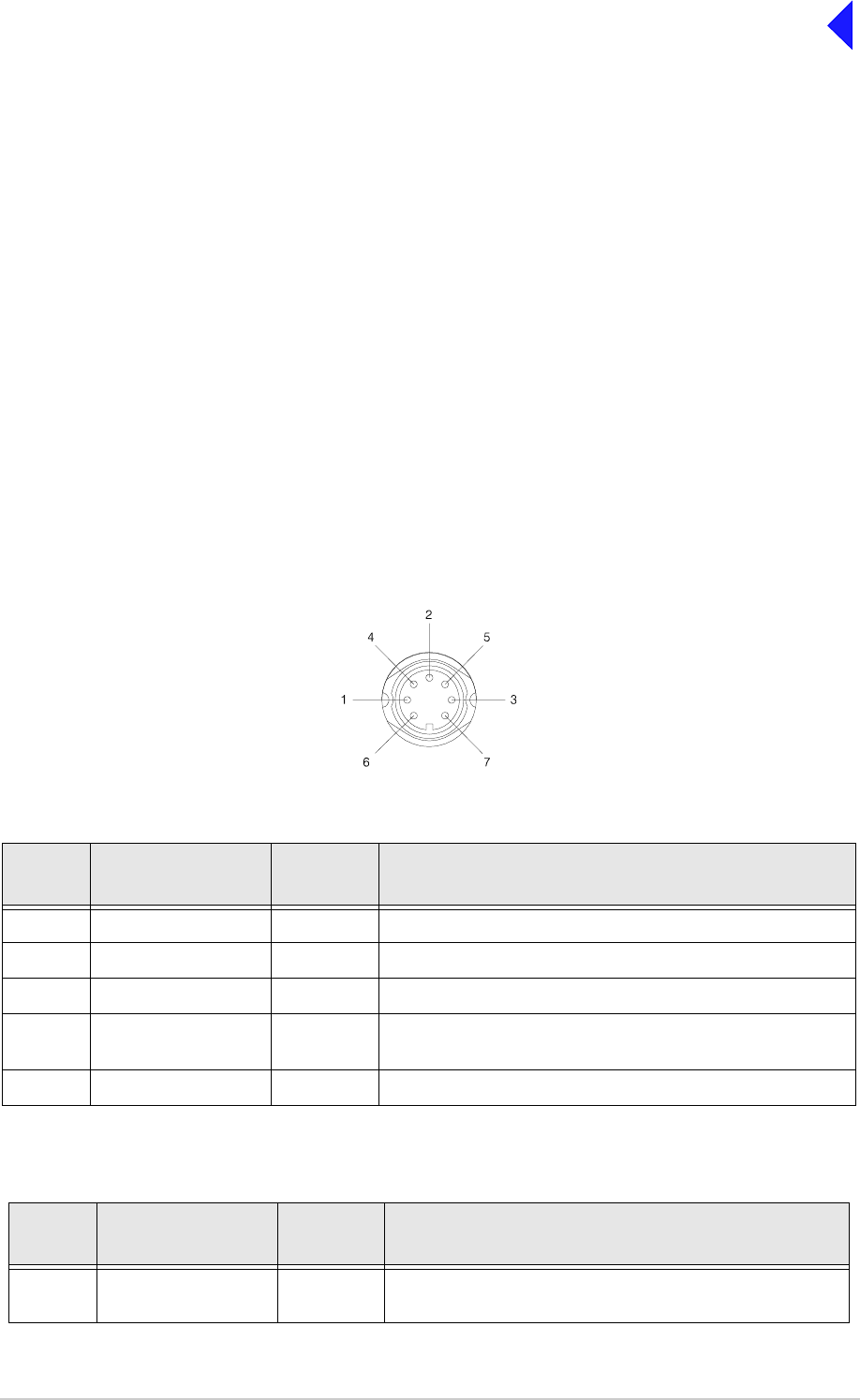
Microphone/Diagnostics Connector
A dual purpose connector that allows either a microphone, or a PC, to be connected to the transmitter.
The connector is a 7-pin self-locking DIN socket; the pin-out is shown in Table 1.
A microphone is fitted to this connector to enable the transmitter to be operated in AM local mode. The
connections are detailed in Table 1. A PC can also be connected to allow the VFP to be displayed. Using
the VFP is detailed in the Maintenance section. The PC connections at the transmitter are shown in
Table 2 on the following page.
Table 1 Microphone/Diagnostics Connector - Audio Connections
Pin
Number Signal Input or
Output Description
1 Microphone ground - 0 V.
3 Microphone PTT Input 0 V to PTT.
5 Sidetone Output 0 to 3 V pk-pk.
6 Microphone input Input 2 to 35 mV rms on Passive setting and 8 to 140 mV rms on
Active setting to remain in VOGAD range.
7Ground - 0V.
Table 2 Microphone/Diagnostics Connector - PC Connections
Pin
Number Signal Input or
Output Description
2 Transmit data Output RS232, 115200 baud, 8 data bits, 1 stop bit, no parity, no
handshaking.
Viewed from front

T6T VHF 100 W Transmitter Page 4 Operation
Back to Transmitter
Main Page
Rear Panel Power Switch
The rear panel power switch is a 2-way rocker switch used to select between power on, and standby.
When the Power switch is set to the Standby position, dangerous voltages are still present
in the transmitter's internal power supply circuitry. To ensure safe working, the transmitter
must be isolated from the ac and dc input supplies.
4 Receive data Input RS232, 115200 baud, 8 data bits, 1 stop bit, no parity, no
handshaking.
7 Ground - 0 V.
Table 2 Microphone/Diagnostics Connector - PC Connections
Pin
Number Signal Input or
Output Description
WARNING Dangerous Voltages
= Standby= On

T6T VHF 100 W Transmitter Page 5 Operation
Back to Transmitter
Main Page
Setting Up and Operation
Introduction
Setting up the transmitter involves using the front panel Scroll/Select switch to specify the operating
parameters.
Operating parameters can also be set using the Virtual Front Panel (VFP), through a Multi-Access
Remote Control (MARC) system, from an associated T6 controller. VFP operation is described on this
disk under Maintenance; MARC and T6 controller functionality is described in separate handbooks.
Table 9 on page 32 details the functions and parameters that can be set from all sources.
No attempt to set up the transmitter should be made until the installation procedures, given in the
Installation topic, are completed.
Normal Operation
During normal operation, the LCD displays the Main screen. This screen shows the operating frequency,
the channel number (if the channel store facility is used), the carrier offset (if used), and displays a
graphical representation of output power when the transmitter is keyed. If the transmitter has been set to
Standby mode, which is shown by the front panel Standby indicator being lit, the LCD is blanked.
Using the Scroll/Select Switch
The Scroll/Select switch (referred to throughout this section as the ‘Switch’) is used to leave the Main
screen and display the Control screen (see page 8). Further use of the Switch displays various selection
menus and allows the required parameters to be set. The switch has three actions: it can be turned
clockwise, anti-clockwise, or momentarily pushed in.
READY
ALARM
TRANSMIT
STANDBY SCROLL/
SELECT
MICROPHONE/
DIAGNOSTICS
REFERENCE
F r e q 1 1 8 .0 0 0 M H z
C h 1 0 0 + 7 . 3 k H z
P w r
Scroll/Select SwitchLCD
M o d e A M V o i c e 1

T6T VHF 100 W Transmitter Page 6 Operation
Back to Transmitter
Main Page
Screen Protocol
The following protocol is applicable to all screens described in this document.
Main Screen During normal operation, the Main screen (an example of which is shown below
whilst the transmitter is transmitting) is displayed.
Switch Refers to the front panel Scroll/Select switch. The switch is turned clockwise to scroll
through fields from left to right, and from top to bottom. The switch is turned
anti-clockwise to scroll through fields from right to left, and from bottom to top. The
switch is pressed to make a selection.
Time out If during any setting up procedure the Scroll/Select switch is not operated for
30 seconds, the display returns to the Main screen. If editing any parameter has not
been completed, the transmitter stays on the original setting.
>> Indicates more fields are available other than those currently displayed. To access
those fields, turn the switch clockwise through the last displayed field.
<< Indicates more fields are available other than those currently displayed. To access
those fields, turn the switch anti-clockwise through the first displayed field.
Back When Back is selected, you are returned to the previous menu.
Exit When Exit is selected, you are returned to the Main screen.
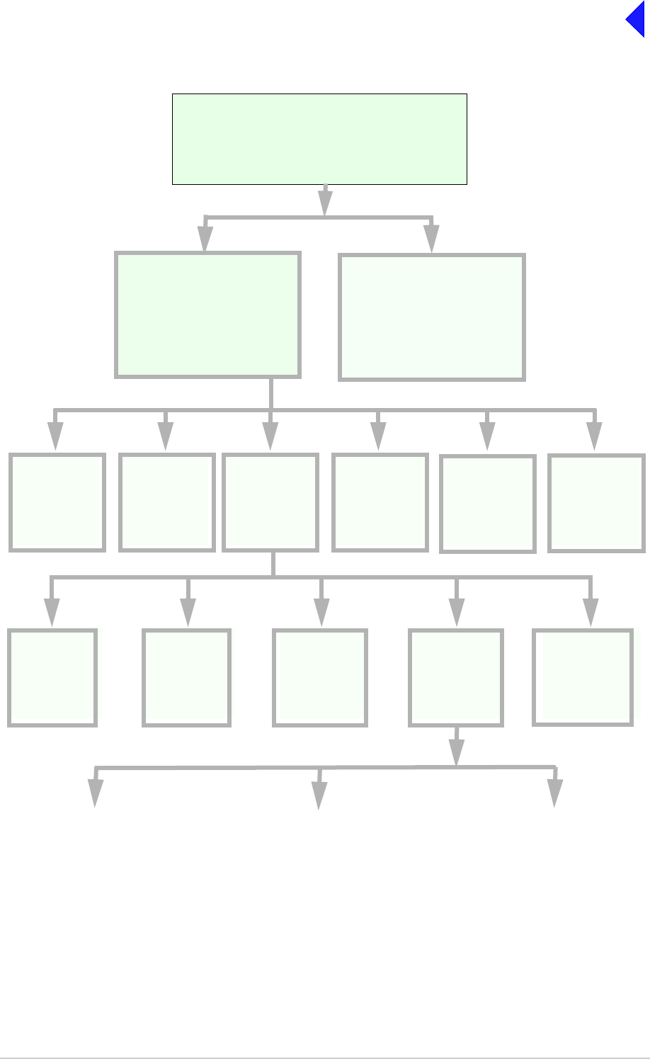
Menu System
The front panel control of the radio is implemented through a hierarchical menu system as shown on the
following page.
F r e q 1 1 8 . 0 0 0 M H z
C h 1 0 0 + 7 . 3 k H z
M o d e A M V o i c e
P w r I I I I I I I I I I
T6T VHF 100 W Transmitter Page 7 Operation
Back to Transmitter
Main Page
Menu System
F r e q 1 1 8 . 0 0 0 M H z
C h 1 0 0
M o d e A M V o i c e
P w r I I I I I I I I I I
Settings
Set the
transmitter
operational
settings
BIT
Initiate a BIT
test and view
results
Standby
Enter or Exit
standby mode
Ref Freq
Adjust the
transmitter
reference
frequency
Band Edges
Set up the
transmitter
band edges
Polarities
Set the active
polarity for
certain hardwire
connections
Backlight
Adjust the
display’s
backlight
AM-Voice Mode
Settings
(see page 17)
AM-MSK Mode
Settings
(see page 19)
Digital Modes
(see page 20)
Mode and
Mode
Settings
Select Mode
Menu Lock Screen
Main Screen
(Example)
Displayed during normal
transmitter operation
Frequency
Set the
transmitter
operating
frequency
Channel
Set or recall up
to 100 preset
frequency
channels
Control Screen
Configure the transmitter
operating parameters, access
the BIT facility or view the
software configuration.
S/W Config
View the
transmitter
software
configuration

T6T VHF 100 W Transmitter Page 8 Operation
Back to Transmitter
Main Page
Menu Lock Screen
A security facility available only from the VFP allows the transmitter front panel to be ‘locked’. When this
facility is active, no operational settings can be made from the front panel until an ‘unlock’ command is
sent from the VFP.
The following screen is displayed when ‘lock’ is active, and the front panel switch is pressed.
To exit the system lock screen:
❑Select OK, then press the switch. You are returned to the Main screen.
or,
❑Wait for the 30 second time out to expire. You are returned to the Main screen.
Control Screen
The Control screen is entered from the Main screen by pressing the switch. The following screen is
displayed:
S E C U R I T Y M E S S A G E
F r o n t P a n e l
L o c k e d
O K
F r e q u e n c y
C h a n n e l
S e t t i n g s
E x i t > >
B I T
S / W C o n f i g
S t a n d b y
E x i t < <
Change the transmitter operating frequency.
Store or recall preset channel frequencies.
Select operating mode and mode settings.
Initiate a BIT test and view results.
View software configuration.
Enter or exit standby mode.

T6T VHF 100 W Transmitter Page 9 Operation
Back to Transmitter
Main Page
Notes for Setting Up the Transmitter
The following notes should be read before setting up the transmitter. They advise on the special
frequency display when using 8.33 kHz channel spacing, and give guidance on the optimum line level
settings. Note that for operation in the United States of America, this equipment is certified only for
operation using 25 kHz channel spacing.
Front Panel Display for 25 kHz and 8.33 kHz Channel Spacing
When setting the operating frequency of the transmitter and 8.33 kHz channel spacing is required, the
displayed frequency differs from the actual channel frequency. Table 3 shows the pattern used for
25 kHz and 8.33 kHz spaced channel frequencies from 118.000 MHz to 118.141 MHz. The pattern is the
same for any frequency within the transmitter's frequency range. The display conforms to ICAO
convention for 8.33 kHz operation.
Table 3 25 kHz and 8.33 kHz Channel Spacing Displays
Actual Frequency
(to 4 decimal places) Channel Spacing Displayed Frequency
at Transmitter's Front Panel
118.0000 MHz
118.0000 MHz
118.0083 MHz
118.0166 MHz
118.0250 MHz
118.0250 MHz
118.0333 MHz
118.0416 MHz
118.0500 MHz
118.0500 MHz
118.0583 MHz
118.0666 MHz
118.0750 MHz
118.0750 MHz
118.0833 MHz
118.0916 MHz
118.1000 MHz
118.1000 MHz
118.1083 MHz
118.1166 MHz
118.1250 MHz
118.1250 MHz
118.1333 MHz
118.1416 MHz
25 kHz
8.33 kHz
8.33 kHz
8.33 kHz
25 kHz
8.33 kHz
8.33 kHz
8.33 kHz
25 kHz
8.33 kHz
8.33 kHz
8.33 kHz
25 kHz
8.33 kHz
8.33 kHz
8.33 kHz
25 kHz
8.33 kHz
8.33 kHz
8.33 kHz
25 kHz
8.33 kHz
8.33 kHz
8.33 kHz
118.000 MHz
118.005 MHz
118.010 MHz
118.015 MHz
118.025 MHz
118.030 MHz
118.035 MHz
118.040 MHz
118.050 MHz
118.055 MHz
118.060 MHz
118.065 MHz
118.075 MHz
118.080 MHz
118.085 MHz
118.090 MHz
118.100 MHz
118.105 MHz
118.110 MHz
118.115 MHz
118.125 MHz
118.130 MHz
118.135 MHz
118.140 MHz

T6T VHF 100 W Transmitter Page 10 Operation
Back to Transmitter
Main Page
Line Level Setting
The input line level setting displayed on the front panel is equivalent to the average speech level with a
peak-to-average ratio of 13 dB. This corresponds to the level specified for the lines.
When testing the transmitter using a sine wave, the line input level should be set to 10 dB above the line
level setting. The VOGAD and mute thresholds are preset at 10 dB and 15 dB respectively below the line
level setting.
Table 4 shows the relationship between the input line level, VOGAD threshold and mute threshold.
Table 4 Relationship Between Line Level, VOGAD Threshold and Mute Threshold
Line Level Setting
(dBm) Average Speech
Level (dBm) Sine Wave Level
(dBm) VOGAD Threshold
(dBm) Mute Threshold
(dBm)
+10 +10 +20 0 -5
+5 +5 +15 -5 -10
00+10-10-15
-5 -5 +5 -15 -20
-10 -10 0 -20 -25
-15 -15 -5 -25 -30
-20 -20 -10 -30 -35
-25 -25 -15 -35 -40
-30 -30 -20 -40 -45

T6T VHF 100 W Transmitter Page 11 Operation
Back to Transmitter
Main Page
Changing the Transmitter Operating Frequency
The transmitter frequency can be changed in two ways: either from the frequency screen, or by recalling
a preset channel. This procedure details the use of the Frequency screen.
F r e q 1 1 8 . 0 0 0 M H z
C a n c e l O K
(1) From the Control screen, select
frequency to display the Frequency
screen.
(2) Turn the switch to highlight the digit to
be changed, then press the switch.
(3) Turn the switch until the required digit
is shown, then press the switch.
(4) Repeat until the required frequency is
shown, then highlight OK and press the
switch.
(5) Only frequencies that fall between the
band edge settings can be selected.

T6T VHF 100 W Transmitter Page 12 Operation
Back to Transmitter
Main Page
To Store and Recall Frequency Channels
Up to 100 frequency channels can be stored in the transmitter.
C h 1 0 0
F r e q 1 2 1 . 5 0 0 M H z
R e c a l l
B a c k E x i t
C h 1 0 0
F r e q 1 1 8 . 0 0 0 M H z
S t o r e
B a c k E x i t
C h 1 0 0
F r e q 1 1 8 . 0 0 0 M H z
I n v a l i d f o r M o d e
B a c k E x i t
C h 1 0 0
F r e q 1 1 8 . 0 0 0 M H z
O u t s i d e B a n d E d g e
B a c k E x i t
To store a Channel Frequency:
(1) From the Control screen, select
Channel to display the Channel
screen. Highlight Channel, press the
switch and then turn it until the required
channel number is displayed; press the
switch.
(2) Highlight the MHz frequency value
(see Example 2) press the switch and
then turn it until the required MHz value
is shown. Press the switch.
(3) Highlight the kHz frequency value (see
Example 3), press the switch and then
turn it until the required kHz value is
shown. Press the switch.
(4) Highlight Store and press the switch.
The new frequency is now stored in the
selected channel number.
To recall a Stored Frequency Channel:
(1) From the Control screen, select
Channel to display the Channel
screen.
(2) To make the transmitter operate on
any preset channel frequency,
highlight Channel and press the switch.
Turn the switch until the required
channel number/frequency is
displayed, then press the switch.
(3) Turn the switch to highlight Recall, then
press the switch. Exit the screen. The
transmitter now operates on the
recalled channel frequency.
Notes:
If a frequency outside the band edge limits is
entered, a message (see Channel Screen -
Example 3) is displayed.
If a frequency not valid for the mode of
operation is entered, a message (see Channel
Screen - Example 4) is displayed.
Channel Screen - Example 1
Channel Screen - Example 2
Channel Screen - Example 3
Channel Screen - Example 4

T6T VHF 100 W Transmitter Page 13 Operation
Back to Transmitter
Main Page
To Initiate a BIT Test
Use the following procedure to initiate an interruptive BIT test from the transmitter front panel. A BIT test
cannot be initiated while the transmitter is keyed. After a BIT test has been run, the BIT screen is
displayed (see AM-Voice and AM-MSK BIT Screen on page 25). An interruptive BIT test cannot be
initiated in Mode 2 or Mode 3.
(1) From the Main screen, press the switch to display the Control screen. Turn the switch until BIT
is highlighted. Press the switch.
(2) Ensure the BIT menu is displayed. Turn the switch until BIT Initiate is highlighted. Press the
switch.
(3) During the test, which takes approximately two seconds, the Testing screen is displayed.
B I T I n i t i a t e
E T I 0 0 0 0 0 : 0 0 h r s
A C S u p p l y O N
E x i t > >
T e s t i n g
P l e a s e W a i t
During an interruptive BIT test, the transmitter radiates modulated carrier waves at the set power.
Users should therefore obtain the necessary authority before initiating a test.
If the test is to be carried out with the antenna disconnected, ensure a load is fitted to the
transmitter's antenna connector.
In order to test the line input stages, an internally generated 1 kHz tone is injected into the line input
circuit. Any other audio present on the line input will cause the test to be inaccurate. Therefore the
transmitter must not be keyed during the test.
B I T
S / W C o n f i g
S t a n d b y
E x i t < <

T6T VHF 100 W Transmitter Page 14 Operation
Back to Transmitter
Main Page
(4) On completion, and if the interruptive test was initiated from the front panel, one of the following
screens will be shown.
(5) Selecting OK takes the user back to the BIT screen.
(6) Selecting OK takes the user back to the BIT screen. The user can then scroll through the screen
to check out transmitter parameters for failure.
Standby Mode
Standby mode is a power saving feature that can be used for non-operational transmitters. When in
standby mode, most of the transmitter's circuits are inactive, the LCD is blanked, and the transmitter
cannot be keyed. To put the transmitter into standby mode, use the following procedure.
When the transmitter is in Standby mode, the red front panel Standby indicator is lit.
To Enter Standby Mode
To Exit Standby Mode
T e s t S t a t u s
P A S S
O K
T e s t S t a t u s
F A I L
O K
E n t e r S t a n d b y ?
Y e s N o
(1) From the Control screen select
Standby.
(2) At the Standby screen, select Yes.
(3) Check that the display blanks and
the front panel Standby indicator is
lit.
E x i t S t a n d b y ?
Y e s N o
(1) Press the Switch.
(2) Select Yes.
(3) Check that the Main screen is
displayed and that the front panel
Standby indicator is unlit.

T6T VHF 100 W Transmitter Page 15 Operation
Back to Transmitter
Main Page
Settings
Operational settings for the T6T 100 W VHF transmitter are configured at the front panel, through the
VFP, and through an associated MARC system (or compatible control system). Some settings can also
be made remotely via a T6 controller. The Settings screen is entered from the Control screen.
The settings that can be selected at the front panel Settings screen are:
❑Mode - either AM-Voice, AM-MSK, Mode 2 or Mode 3
❑Mode settings - allows the selected mode parameters to be set
❑Polarities
❑Band edges
❑Backlight
❑Reference frequency.
Note that the mode selection, reference frequency and backlight are set from this screen. When mode
settings, polarities and band edges are selected the user is taken to other screens.
General and mode specific settings, showing default values, are referenced in Table 5 on the following
page. Click on any required parameter by page number for further references.
M o d e A M V o i c e
M o d e S e t t i n g s
P o l a r i t i e s
E x i t > >
B a n d E d g e s
R e f F r e q 5 0 . 0 %
B a c k l i g h t 0 3 0 s
E x i t < < > >
B a c k
E x i t
Select between AM-Voice, AM-MSK, Mode 2 or Mode 3.
Select to take you to the mode specific Settings menu.
Select to take you to the Polarities menu.
Set the transmitter’s frequency band edges.
Align the transmitter’s reference frequency (Note 1).
Adjust the LCD’s backlight time out (Note 2).
Notes:
1. Setting the transmitter reference frequency is a maintenance operation. The current value
should not be reset unless the correct test equipment is connected. See the Maintenance
section.
2. The LCD backlight can be set for permanently on, off, or timed to stay on for a period between
15 and 120 seconds.

T6T VHF 100 W Transmitter Page 16 Operation
Back to Transmitter
Main Page
Table 5 Operational Settings from the Front Panel
Parameter Mode Adjustment Range Factory Default Setting Further
Reference
Menu lock screen All Locked or unlocked Unlocked page 8
Enter standby
mode All Yes or No - page 14
Exit standby mode All Yes or No - page 14
Set mode of
operation All AM-Voice, AM-MSK, Mode
2 or Mode 3 AM-Voice page 15
Set polarities AM-Voice,
AM-MSK STD or INV STD page 21
Band edges All 118.000 to 136.975 MHz 118.000 and 136.975 MHz page 29
LCD backlight All 15 to 120 s, On or Off 30 s page 15
RF power All 10 to 100 W 100 W page 17
Audio line in level AM-Voice,
AM-MSK -30 to +10 dBm -13 dBm page 17 and
page 19
Inhibit AM-Voice,
AM-MSK On or Off Off page 17 and
page 19
PTT (key) AM-Voice,
AM-MSK On (key), Off (de-key) Off page 17 and
page 19
Tx time out AM-Voice,
AM-MSK 2 to 510 s or Off 180 s page 17 and
page 19
Modulation depth AM-Voice,
AM-MSK 5 to 95% 85% page 17 and
page 19
Mute AM-Voice On or Off On page 17
VOGAD AM-Voice On or Off On page 17
Antenna C/O delay AM-Voice
AM-MSK On or Off On
Off
page 17
page 19
Offset AM-Voice 0, ±2.5, ±4, ±5, ±7.3, ±7.5,
±8 kHz 0 (No offset) page 18
Step AM-Voice 8.33 kHz, 25 kHz or both 25 kHz page 18
Mic AM-Voice Active or Passive Passive page 18
Key priority AM-Voice,
AM-MSK Local-Remote or
Remote-Local Local-Remote page 18 and
page 19
Local PTT AM-Voice,
AM-MSK Enabled or Disabled Enabled page 18 and
page 19
Remote PTT AM-Voice,
AM-MSK Enabled or Disabled Enabled page 18 and
page 19
Remote phantom
PTT AM-Voice,
AM-MSK Enabled or Disabled Enabled page 18 and
page 19

T6T VHF 100 W Transmitter Page 17 Operation
Back to Transmitter
Main Page
AM-Voice Settings Procedure
During this procedure, the following parameters, applicable to AM-Voice operation, can be set:
❑RF power output
❑Audio line input level
❑Inhibit
❑PTT on (key) or off (de-key)
❑Transmitter time out
❑Modulation depth
❑Mute (on or off)
❑VOGAD (on or off)
❑Antenna c/o delay (on or off)
❑Offset
❑Step
❑Mic
❑Key priority (local or remote)
❑Enable or disable local PTT
❑Enable or disable remote PTT
❑Enable or disable remote phantom PTT.
AM-Voice Mode Settings Screen
The AM-Voice mode setting screen is accessed from the Settings screen. Use the Scroll/Select switch
to select the parameter, then enter the required setting(s).
P o w e r 1 0 0 W
L i n e I n - 1 3 d B m
I n h i b i t O F F
E x i t > >
P T T O F F
T X T i m e o u t 1 8 0 s
M o d D e p t h 8 5 %
E x i t < < > >
M u t e O N
V O G A D O N
A n t C / O D e l O N
E x i t < < > >
Adjustments
RF power between 10 W to 100 W.
Audio line in level between -30 to +10 dBm.
On or Off.
On (key), Off (de-key).
2 to 510 s.
5 to 95%.
On or Off.
On or Off.
On or Off.

T6T VHF 100 W Transmitter Page 18 Operation
Back to Transmitter
Main Page
O f f s e t 0 . 0 k H z
S t e p 2 5 k H z
M i c P A S S I V E
E x i t < < > >
K e y P r i o r i t y L - R
L o c a l P T T E N
R e m o t e P T T E N
E x i t < < > >
R e m P h a n P T T E N
B a c k
E x i t < <
Adjustments
0, ±2.5, ±4, ±5, ±7.3, ±7.5, ±8 kHz.
25 kHz, 8.33 kHz or both.
Active or Passive.
Local-remote or Remote-local.
Enabled or Disabled.
Enabled or Disabled.
Enabled or Disabled.
Return to Settings screen.

T6T VHF 100 W Transmitter Page 19 Operation
Back to Transmitter
Main Page
AM-MSK Mode Settings Procedure
During this procedure, the following parameters, applicable to AM-MSK operation, can be set:
❑RF power output
❑Audio line input level
❑Inhibit
❑PTT on (key) or off (de-key)
❑Transmitter time out
❑Modulation depth
❑Antenna c/o delay (on or off)
❑Key priority (local or remote)
❑Enable or disable local PTT
❑Enable or disable remote PTT
❑Enable or disable remote phantom PTT.
AM-MSK Mode Settings Screens
The AM-MSK mode setting screen is accessed from the Settings screen. Use the Scroll/Select switch to
select the parameter, then enter the required setting(s).
P o w e r 1 0 0 W
L i n e I n - 1 3 d B m
I n h i b i t O F F
E x i t > >
P T T O F F
T X T i m e o u t 1 8 0 s
M o d D e p t h 8 5 %
E x i t < < > >
A n t C / O D e l O N
K e y P r i o r i t y L - R
L o c a l P T T E N
E x i t < < > >
R e m o t e P T T E N
R e m P h a n P T T E N
B a c k
E x i t < <
Adjustments
RF power between 10 W to 100 W.
Audio line in level between -30 to +10 dBm.
On or Off.
On (key), Off (de-key).
2 to 510 s.
5 to 95%.
On or Off.
Local-remote or Remote-local.
Enabled or Disabled.
Enabled or Disabled.
Enabled or Disabled.

T6T VHF 100 W Transmitter Page 20 Operation
Back to Transmitter
Main Page
Mode 2 Settings Screen
This is an advisory screen. Pressing OK returns the user to the Main screen.
Mode 3 Settings Screen
This is an advisory screen. Pressing OK returns the user to the Main screen.
M o d e 2 p a r a m e t e r s
a r e s e t v i a t h e
H L D C i n t e r f a c e
O K
M o d e 3 p a r a m e t e r s
a r e s e t v i a t h e
T 1 / E 1 i n t e r f a c e
O K

T6T VHF 100 W Transmitter Page 21 Operation
Back to Transmitter
Main Page
Polarities Screens AM-Voice and AM-MSK
A number of remote indication and control signals can be hardwire connected to the transmitter. These
signals include a transmitter ready indication, a PTT control signal, a phantom PTT control signal, a PTT
out indication, a transmitter inhibit control signal, an E-BIT input, a BIT test initiation control signal, an
external VSWR fault indication and antenna C/O. The following paragraphs detail the signals applicable
to the operational mode of the transmitter.
The Polarities screen is accessed from the Settings screen.
AM-Voice and AM-MSK Polarity Settings
Each of ten polarity settings applicable to AM-Voice and AM-MSK can be set to the default STD
(standard) setting or INV (inverted).
The signal connections are shown in Table 6 along with the conditions when STD or INV is selected.
The settings for the PTT Reference voltage are also shown in Table 6.
R e a d y O u t S T D
E - B I T I n S T D
I n h i b i t I n S T D
E x i t > >
B I T S t a r t I n S T D
P T T R e f + 1 4 V
P T T I n S T D
E x i t > >
P h a n P T T I n S T D
P T T O u t S T D
F a s t P T T O u t S T D
E x i t < < > >
E x t V S W R I n S T D
A n t C / O O u t S T D
B a c k
E x i t < <

T6T VHF 100 W Transmitter Page 22 Operation
Back to Transmitter
Main Page
Table 6 AM-Voice and AM-MSK Polarity Settings
Signal Connector Polarity set to STD Polarity set to INV
Ready Out Facilities, pin 13 An open collector grounded
output when the radio is ready
to transmit and no BIT faults
are detected.
An open collector high
impedance output when the
radio is ready to transmit and
no BIT faults are detected.
E-BIT In Facilities, pin 2 TTL input. 0 V indicates an
external fault. TTL input. 5 V indicates an
external fault.
Inhibit In Facilities, pin 10 TTL input. 0 V inhibits
transmitter operation. TTL input. 5 V inhibits
transmitter operation.
BIT Start In Facilities, pin 11 TTL input. 0 V initiates an
interruptive BIT test. TTL input. 5 V initiates an
interruptive BIT test.
PTT In MARC, pin 4
MARC Audio, pin 6 Active when input differs from
reference by more than 10 V.
Inactive when input differs from
reference by less than 1 V.
Maximum input level ±60 V
with respect to reference. Input
will draw no more than 6 mA,
requires at least 1 mA to
operate.
Active when input differs from
reference by less than 1 V.
Inactive when input differs from
reference by more than 10 V.
Maximum input level ±60 V
with respect to reference. Input
will draw no more than 6 mA,
requires at least 1 mA to
operate.
Phantom PTT In
(Phan PTT In)
MARC or
MARC Audio, pin 2 Active when input differs from
reference by more than 10 V.
Inactive when input differs from
reference by less than 1 V.
Maximum input level ±60 V
with respect to reference. Input
will draw no more than 6 mA,
requires at least 1 mA to
operate.
Active when input differs from
reference by less than 1 V.
Inactive when input differs from
reference by more than 10 V.
Maximum input level +60 V
with respect to reference. Input
will draw no more than 6 mA,
requires at least 1 mA to
operate.
PTT Out Facilities, pin 3 Grounding solid state relay.
+60 to -60 V, ac or dc, 100 mA
max, n/o. Activated 20 ms
(±1 ms) before the start of the
power ramp up to allow for the
antenna relay to pull-in time.
Grounding solid state relay.
+60 to -60 V, ac or dc, 100 mA
max, n/c. Activated 20 ms
(±1 ms) before the start of the
power ramp up to allow for the
antenna relay to pull-in time
External VSWR
Input
(Ext VSWR In)
Facilities, pin 4 TTL input. 0 V active. TTL input. 5 V active.
Antenna
Changeover
(Ant c/o out)
Facilities, pin 5
(Common pin 6) Solid state relay. +60 to -60V,
ac or dc, 100 mA max, n/o.
Activated 35 ms (±1 ms) before
the start of the power ramp up
to allow for the antenna relay
pull-in time.
Solid state relay. +60 to -60V,
ac or dc, 100 mA max, n/c.
Activated 35 ms (±1 ms) before
the start of the power ramp up
to allow for the antenna relay
pull-in time.
Continued >>

T6T VHF 100 W Transmitter Page 23 Operation
Back to Transmitter
Main Page
Fast PTT Output
(antenna
change-over)
MARC Audio, pin 3 Open collector NPN transistor
grounding output, 200 mA max,
n/o.
Open collector NPN transistor
grounding output, 200 mA max,
n/c.
PTT Ref - PTT Ref can be set to +14 V,
0 V or -14 V. PTT. Maximum
input level ±60 V with respect
to PTT reference. Input will
draw no more than 6 mA, and
requires at least 1 mA to
operate.
When the input PTT signal and
the PTT reference differ by
more than 10 V the radio keys.
When the input PTT signal and
the PTT reference are within
1 V, the radio dekeys.
Other conditions are
indeterminable.
PTT Ref can be set to +14 V,
0 V or -14 V. PTT. Maximum
input level ±60 V with respect
to PTT reference. Input will
draw no more than 6 mA, and
requires at least 1 mA to
operate.
When the input PTT signal and
the PTT reference differ by
more than 10 V the radio
dekeys.
When the input PTT signal and
the PTT reference are within
1 V, the radio keys.
Other conditions are
indeterminable.
Table 6 AM-Voice and AM-MSK Polarity Settings (Continued)
Signal Connector Polarity set to STD Polarity set to INV

T6T VHF 100 W Transmitter Page 24 Operation
Back to Transmitter
Main Page
Mode 2 and Mode 3 Polarity Settings
Table 7 Mode 2 and Mode 3 Polarity Settings
Signal Connector Polarity set to STD Polarity set to INV
Ready Out Facilities, pin 13 An open collector grounded
output when the radio is ready
to transmit and no BIT faults
are detected.
An open collector high
impedance output when the radio
is ready to transmit and no BIT
faults are detected.
E-BIT In Facilities, pin 2 TTL input. 0 V indicates an
external fault. TTL input. 5 V indicates an
external fault.
External VSWR
Input Facilities, pin 4 TTL input. 0 V active. TTL input. 5 V active.
R e a d y O u t S T D
E - B I T I n S T D
E x t V S W R I n S T D
E x i t > >
B a c k
E x i t
< <
Each of the three polarity settings applicable to
Mode 2 and Mode 3 can be set to the default STD
(standard) setting or INV (inverted).
The signal connections are detailed in Table 7
along with the conditions when STD or INV is
selected.

T6T VHF 100 W Transmitter Page 25 Operation
Back to Transmitter
Main Page
AM-Voice and AM-MSK BIT Screen
The AM-Voice and AM-MSK BIT screen is accessed from the Control screen.
B I T I n i t i a t e
E T I 0 0 0 0 0 : 0 0 h r s
A C S u p p l y O N
E x i t > >
D C S u p p l y O N
S u p p l y 2 8 V
S y n t h L o c k P A S S
E x i t < < > >
P A T e m p 5 0 d e g C
P A C o o l i n g P A S S
B a s e b a n d P A S S
E x i t < < > >
R F D r i v e P A S S
P A O u t p u t P A S S
P A L o o p P A S S
E x i t < < > >
M o d D e p t h P A S S
R F F i l t e r s P A S S
V S W R P A S S
E x i t < < > >
L o o p E r r o r P A S S
A u d i o I n P A S S
D S P 1 P A S S
E x i t < < > >
Select to initiate BIT test.
Shows elapsed time 0:00 to 99999:59 (Hrs:Min).
Shows state of ac supply (On or Off).
PA temperature -20°C to +150°C.
Pass or Fail.
Pass, Fail or Not Tested.
Pass, Fail or Not Tested.
Pass, Fail or Not Tested.
Pass, Fail or Not Tested.
Shows state of dc supply (On or Off).
dc supply 0 to 40 V, <21.6 V Alert, <19 V Alarm.
Pass or Fail (Out-of-Lock).
Pass, Fail or Not Tested.
Pass, Fail or Not Tested.
Pass, Fail or Not Tested.
Pass or Fail.
Pass, Fail or Not Tested.
Pass or Fail.

T6T VHF 100 W Transmitter Page 26 Operation
Back to Transmitter
Main Page
D S P 2 P A S S
X i l i n x 1 P A S S
X i l i n x 2 P A S S
E x i t < < > >
E E P R O M P A S S
S t a r t U p P A S S
C a l i b r a t i o n P A S S
E x i t < < > >
U n k e y e d P w r P A S S
E - B I T P A S S
M A R C A C T I V E
E x i t < < > >
H D L C I N A C T I V E
T 1 / E 1 I N A C T I V E
B a c k
E x i t < <
Pass or Fail.
Pass or Fail.
Pass or Fail.
Pass or Fail.
Pass or Fail.
Active or Inactive.
Pass or Fail.
Pass or Fail.
Pass or Fail.
Active or Inactive.
Active or Inactive.

T6T VHF 100 W Transmitter Page 27 Operation
Back to Transmitter
Main Page
Mode 2 and Mode 3 BIT Screen
The Mode 2 and Mode 3 BIT screen is accessed from the Control screen.
E T I 0 0 0 0 0 : 0 0 h r s
A C S u p p l y O N
D C S u p p l y O N
E x i t > >
S u p p l y 2 8 V
S y n t h L o c k P A S S
P A T e m p 5 0 d e g C
E x i t < < > >
P A C o o l i n g P A S S
V S W R P A S S
L o o p E r r o r P A S S
E x i t < < > >
D S P 1 P A S S
D S P 2 P A S S
X i l i n x 1 P A S S
E x i t < < > >
X i l i n x 2 P A S S
E E P R O M P A S S
S t a r t U p P A S S
E x i t < < > >
C a l i b r a t i o n P A S S
E - B I T P A S S
M A R C A C T I V E
E x i t < < > >
Shows elapsed time 0:00 to 99999:59 (Hrs:Min).
Shows state of ac supply (On or Off).
Shows state of dc supply (On or Off).
Shows value of dc supply.
Synth lock (Pass or Fail).
Indicates the PA temperature.
Pass or Fail.
Pass or Fail.
Pass or Fail.
Pass or Fail.
Pass or Fail.
Pass or Fail.
Pass or Fail.
Pass, Fail or Not Tested.
Pass or Fail.
Pass or Fail.
Pass or Fail.
Active or Inactive.
H D L C I N A C T I V E
T 1 / E 1 I N A C T I V E
B a c k
E x i t < <
Active or Inactive.
Active or Inactive.

T6T VHF 100 W Transmitter Page 28 Operation
Back to Transmitter
Main Page
Software Configuration Screens
Software configuration screens are as follows:
T 6 V H F 1 0 0 W T X
1 1 8 - 1 3 6 . 9 7 5 M H z
H i g h S t a b i l i t y
E x i t > >
B o o t S o f t w a r e
6 5 - x x x x x x x x / v v
E x i t < < > >
B a s e S o f t w a r e
6 5 - x x x x x x x x / v v
E x i t < < > >
M o d e S o f t w a r e
6 5 - x x x x x x x x / v v
E x i t < < > >
F i l l 1 S o f t w a r e
6 5 - x x x x x x x x / v v
[ D e s c r i p t i o n ]
E x i t < < > >
F i l l 2 S o f t w a r e
6 5 - x x x x x x x x / v v
[ D e s c r i p t i o n ]
E x i t < < > >
The first screen defines the radio.
65-xxxxxxxx represents the software part
number and /v v represents its version.
65-xxxxxxxx represents the software part
number and /v v represents its version.
Current mode running. 65-xxxxxxxx
represents the software part number and /v v
represents its version.
65-xxxxxxxx represents the software part
number and /v v represents its version.
65-xxxxxxxx represents the software part
number and /v v represents its version.

T6T VHF 100 W Transmitter Page 29 Operation
Back to Transmitter
Main Page
F i l l 3 S o f t w a r e
6 5 - x x x x x x x x / v v
[ D e s c r i p t i o n ]
F i l l 4 S o f t w a r e
6 5 - x x x x x x x x / v v
[ D e s c r i p t i o n ]
65-xxxxxxxx represents the software part number
and /v v represents its version.
65-xxxxxxxx represents the software part number
and /v v represents its version.

T6T VHF 100 W Transmitter Page 30 Operation
Back to Transmitter
Main Page
Band Edges
The frequency range of the T6 100 W transmitter is 118 to 136.975 MHz. If required, transmission can
be limited to either one or two smaller parts of the frequency band by setting the band edges, BE1 to
BE4. Transmission is possible between BE1 and BE2 frequencies, and between BE3 and BE4
frequencies.
Table 8 Band Edge Settings
BE1 BE2 BE3 BE4
B63100HS/NB set so that the full frequency range can be
transmitted. 118.000 136.975 118.000 136.975
Example: Transmitter set to transmit only those frequencies
in the range 120 to 130 MHz. 120.000 130.000 120.000 130.000
Example: Transmitter set to transmit only those frequencies
in the ranges 120 to 125 MHz and 130 to 135 MHz. 120.000 125.000 130.000 135.000
B E 1 1 1 8 . 0 0 0 M H z
B E 2 1 3 6 . 9 7 5 M H z
B E 3 1 1 8 . 0 0 0 M H z
E x i t > >
B E 4 1 3 6 . 9 7 5 M H z
E x i t < <
The Band Edge screen is accessed from the
Control screen.
Band edge frequencies can be set only in
increments of 25 kHz.
If the transmitter is required to operate over the
full range, the band edge parameters must be set
to the lowest and highest values in the range (see
Table 8).

T6T VHF 100 W Transmitter Page 31 Operation
Back to Transmitter
Main Page
BIT Status Warning Screens
The following shows some example BIT screens. These screens alternate with the Main screen when an
alert or alarm condition is present. Only the parameters causing the alert or alarm are displayed, and if
both an alert and alarm condition exists simultaneously only the alarm information is displayed. If multiple
parameters are signalling an alert or alarm condition, multiple screens are used to display the status
alternating with the Main screen.
A L E R T
S u p p l y 2 1 V
A L E R T
R F P o w e r R e d u c e d
L o o p E r r o r
S u p p l y 2 1 V
A L E R T
R F P o w e r R e d u c e d
P A T e m p 8 5 d e g C
A L A R M
R F P o w e r R e d u c e d
V S W R F A I L
A L A R M
R F P o w e r R e m o v e d
L o o p E r r o r F A I L
S u p p l y 1 8 V
A L A R M
R F P o w e r R e m o v e d
P A T e m p 9 5 d e g C
Alert:
There is no RF power reduction. The Alarm
indicator is flashing.
Alert:
The RF output power is reduced between 1 and
3 dB. The Alarm indicator is flashing.
Alert:
The RF output power is reduced between 1 and
3 dB. The Alarm indicator flashing
Alarm:
The RF output power reduced by more than 3
dB. The Alarm indicator is lit.
Alarm:
The RF output power is shut down. The Alarm
indicator is lit.
Alarm:
The RF output power is shut down. The Alarm
indicator is lit.

T6T VHF 100 W Transmitter Page 32 Operation
Back to Transmitter
Main Page
Table 9 Functions and Parameters
Function Front
Panel VFP MARC T6
Controller T1/E1 HDLC Default Setting
FREQUENCY
Change frequency 118.000 MHz
FREQUENCY CHANNELS
Store/Recall preset
frequency channels -
SETTINGS
Set modulation
mode AM-Voice
Radio Settings (AM Modes)
Set RF output
power 100 W
Set audio input line
level -13 dBm
Set inhibit on or off Off
PTT test facility
on (key), off (de-
key)
View
state Off
Set Tx time out 180 s
Set modulation
depth 85%
Set mute on or off
(AM-Voice only) On
Set VOGAD on
or off
(AM-Voice only)
On
Set antenna C/O
delay on or off AM-Voice - On
AM-MSK - Off
Set frequency offset
(AM-Voice only) 0 (No offset)
Set frequency step
size
(AM-Voice only)
25 kHz
Continued >>

T6T VHF 100 W Transmitter Page 33 Operation
Back to Transmitter
Main Page
Set microphone
type
(active or passive)
(AM-Voice only)
Passive
Set keying priority
(local or remote) Local-Remote
Enable or disable
local PTT Enabled
Enable or disable
remote PTT Enabled
Enable or disable
remote phantom
PTT
Enabled
Radio Settings (Digital Modes)
MAC TM1 (inter
access delay) 2.5 ms
MAC TM2 (channel
busy) 60 s
MAC p
(persistance) 13/256
MAC M1 (maximum
number of access
attempts)
135
Scramble vector 4D4B
19787
Tx enable On
Polarities
Ready out
View
state STD
Set PTT input
polarity
(AM modes only)
View
state STD
Set phantom PTT
input polarity
(AM modes only)
View
state STD
Continued >>
Table 9 Functions and Parameters (Continued)
Function Front
Panel VFP MARC T6
Controller T1/E1 HDLC Default Setting

T6T VHF 100 W Transmitter Page 34 Operation
Back to Transmitter
Main Page
Set PTT reference
voltage
(AM modes only)
View
state +14 V
Set PTT output
polarity
(AM modes only)
View
state STD
Set fast PTT
antenna change-
over output polarity
(AM modes only)
View
state STD
Set antenna
change-over output
polarity
(AM modes only)
View
state STD
Set external VSWR
input polarity
(All modes)
View
state STD
Set inhibit input
polarity
(AM modes only)
View
state STD
BIT interruptive test
input polarity
(AM modes only)
View
state STD (active low)
E-bit input polarity
(All modes)
View
state STD (active low)
Band Edges
Set band edges
118.000 and 136.975 MHz
Reference Frequency
Adjust transmitter’s
reference frequency -
LCD Backlight
Adjust LCD
backlight 30 s
Continued >>
BIT
Table 9 Functions and Parameters (Continued)
Function Front
Panel VFP MARC T6
Controller T1/E1 HDLC Default Setting

T6T VHF 100 W Transmitter Page 35 Operation
Back to Transmitter
Main Page
Initiate BIT
interruptive test -
STANDBY
Enter and exit
standby facility Not in Standby
SOFTWARE CONFIGURATION
View the
transmitter’s
software
configuration
-
LOCK FACILITIES
Front panel lock Off
MARC lock Off
T1/E1 lock Off
HDLC lock Off
Table 9 Functions and Parameters (Continued)
Function Front
Panel VFP MARC T6
Controller T1/E1 HDLC Default Setting

Back to Transmitter
Main Page
Intentionally Blank

Back to Transmitter
Main Page
Installation
This topic gives the information required to install a T6T VHF 100 W Multimode Transmitter.
T6T VHF 100 W Transmitter Page 2 Installation
Back to Transmitter
Main Page
Warnings and Cautions
The instructions given in this topic involve connecting dangerous voltages to the transmitter
and should be carried out only by suitably qualified personnel.
The equipment is permanently connected to the mains supply when the mains connector is
attached. Switching the rear panel Power switch to off does not isolate all internal circuits
from the mains supply. For this reason, a mains isolating switch should be fitted close to,
and easily accessible from, the transmitter's position. The isolation switch should isolate
both live and neutral supplies, be clearly labelled, and adequately rated to protect the
equipment.
The antenna used with the transmitter must be installed such that the resultant radiated field
strength is below 10 W/m² in areas normally accessible to personnel.
The T6T transmitter's circuitry contains Electrostatic Sensitive Devices (ESSDs). Personnel
must be aware of the precautions necessary to prevent damage to such devices. During
installation all precautions necessary to prevent ESSD damage must be taken.
Changes or modifications made to this equipment that are not expressly approved by
Park Air, or parties authorized by Park Air, could void the user’s authority to operate the
equipment.
WARNING Dangerous Voltages
WARNING Dangerous Voltages
WARNING Antenna Radiation
Caution ESSDs
Caution Unauthorized Modifications
T6T VHF 100 W Transmitter Page 3 Installation
Back to Transmitter
Main Page
Introduction
The procedures necessary to install a transmitter are listed in Table 1.
Fuses and Connectors
The following list details the radio’s supply fuses and connectors. Some of the connectors (depending on
your particular configuration) are required during installation.
Table 1 Installation Procedures
Procedure Reference
1 Read and understand the warnings and cautions given on page 2.
2 Perform an initial inspection of the transmitter and fit the correct ac input fuse. page 9
3 Fit the transmitter into an equipment cabinet. page 9
4 Make external signal connections. See Fig 1 to Fig 5 to determine which
external connections are required for the particular configuration. page 10
5 Connect the chassis stud to the cabinet or system earth. page 22
6 Connect the antenna. page 22
7 Connect the dc input supply (if required). page 22
8 Connect the ac input supply (if required). page 23
Table 2 Fuses and Connectors
Component Type Park Air Part Number
Fuses:
AC input fuses, F3, F4 for 110/120 V input
AC input fuses, F3, F4 for 220/230 V input T4A, 125V, UL
T4A, 250V, IEC 29C11120102S
29E01120108S
DC input fuses, F1, F2 15A size 0 29-01350201
Connectors:
AC supply connectors IEC 20-02030102
DC supply connectors XLR 3-pin 20-01030106
Antenna connector N-type plug 19-01030301
MARC connector 9-way D-type plug Plug: 20-01090100
Cover: 20-09090101
MARC audio RJ48 plug 20K01080100
MARC data RJ48 plug 20K01080100
Facilities connector 15-way D-type plug Plug: 20-01150100
Cover: 20-09150101
HDLC connector RJ48 plug 20K01080100
T1/E1 connector RJ48 plug 20K01080100
Reference connector SMB connector 19C01050300
Microphone/Diagnostics connector 7-pin DIN plug 20-01070101
T6T VHF 100 W Transmitter Page 4 Installation
Back to Transmitter
Main Page
Configuration
Connection of external equipment depends on the configuration required. Possible configurations are:
❑T6T transmitter configured for local operation (see Fig 1).
❑T6T transmitter configured for remote operation (see Fig 2).
❑T6T transmitter configured for use with MARC (see Fig 3).
❑T6T Mode 2 configuration (see Fig 4).
❑T6T Mode 3 configuration. (see Fig 5).
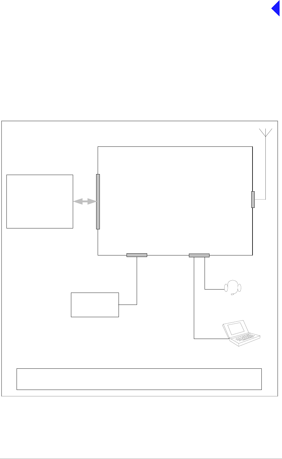
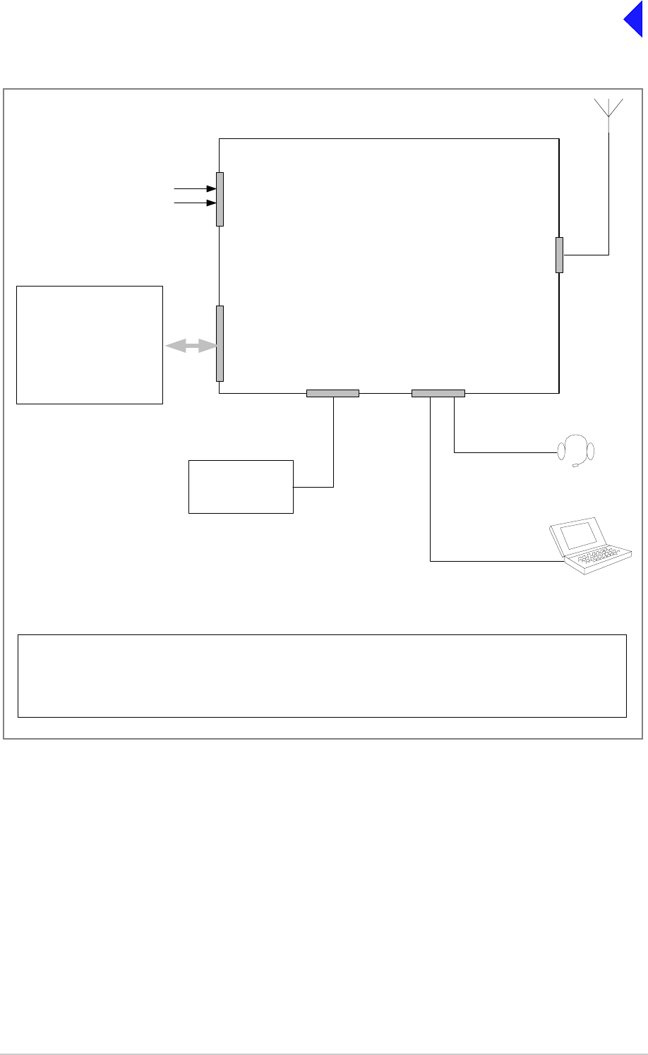
Fig 1 T6T Transmitter Configured for Local Operation
For local operation, the transmitter is operated from the front panel using a microphone/headset.
Any of the optional facilities may be connected.
Antenna
Connector
Reference
Connector Microphone/Diagnostics
Connector
Frequency Counter
required only for
maintenance
Facilities
Connector
T6T Transmitter
E-BIT input
PTT relay output
External VSWR input
dc supply output
Inhibit input
BIT interruptive test input
Antenna change-over output
Ready output
Tape output
Optional Facilities that
can be used if required
Laptop (or PC) required
only for maintenance
Mic/Headset for
local operation
T6T VHF 100 W Transmitter Page 5 Installation
Back to Transmitter
Main Page
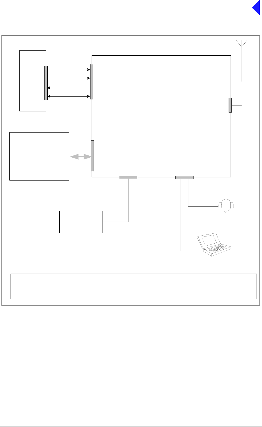
Fig 2 T6T Transmitter Configured for Remote Operation
For remote operation, Audio and PTT signals from the control equipment terminate on the MARC
connector, or alternatively on the MARC Audio connector. If data is required by a compatible data system,
the RS422 data lines terminate on the MARC connector, or alternatively on the MARC Data connector.
Any of the optional facilities may be connected.
Antenna
Connector
Microphone/Diagnostics
Connector
MARC Connector
or,
MARC Audio Connector
Mic/Headset for
engineering use
Laptop (or PC) required
only for maintenance
T6T Transmitter
Optional Facilities that
can be used if required
E-BIT input
PTT relay output
External VSWR input
dc supply output
Inhibit input
BIT interruptive test input
Antenna change-over output
Ready output
Tape output
Reference
Connector
Frequency Counter
required only for
maintenance
Facilities
Connector
Audio
PTT
T6T VHF 100 W Transmitter Page 6 Installation
Back to Transmitter
Main Page
Fig 3 T6T Transmitter Configured for use with MARC
When using a T6T transmitter with a MARC Remote Site Equipment (RSE2) the transmitter MARC
connector is pin-to-pin wired to one of the RSE2 Equipment connectors.
Any of the optional facilities may be connected.
Antenna
Connector
Reference
Connector Microphone/Diagnostics
Connector
T6T Transmitter
Equipment
Connector
RSE2
MARC
Connector
Audio
PTT
RS422 data
dc supply output
E-BIT input
PTT relay output
External VSWR input
Unregulated supply output
Inhibit input
BIT interruptive test input
Antenna change-over output
Ready output
Tape output
Facilities
Connector
Frequency Counter
required only for
maintenance
Mic/Headset for
engineering use
Laptop (or PC) required
only for maintenance
Optional Facilities that
can be used if required
T6T VHF 100 W Transmitter Page 7 Installation
Back to Transmitter
Main Page
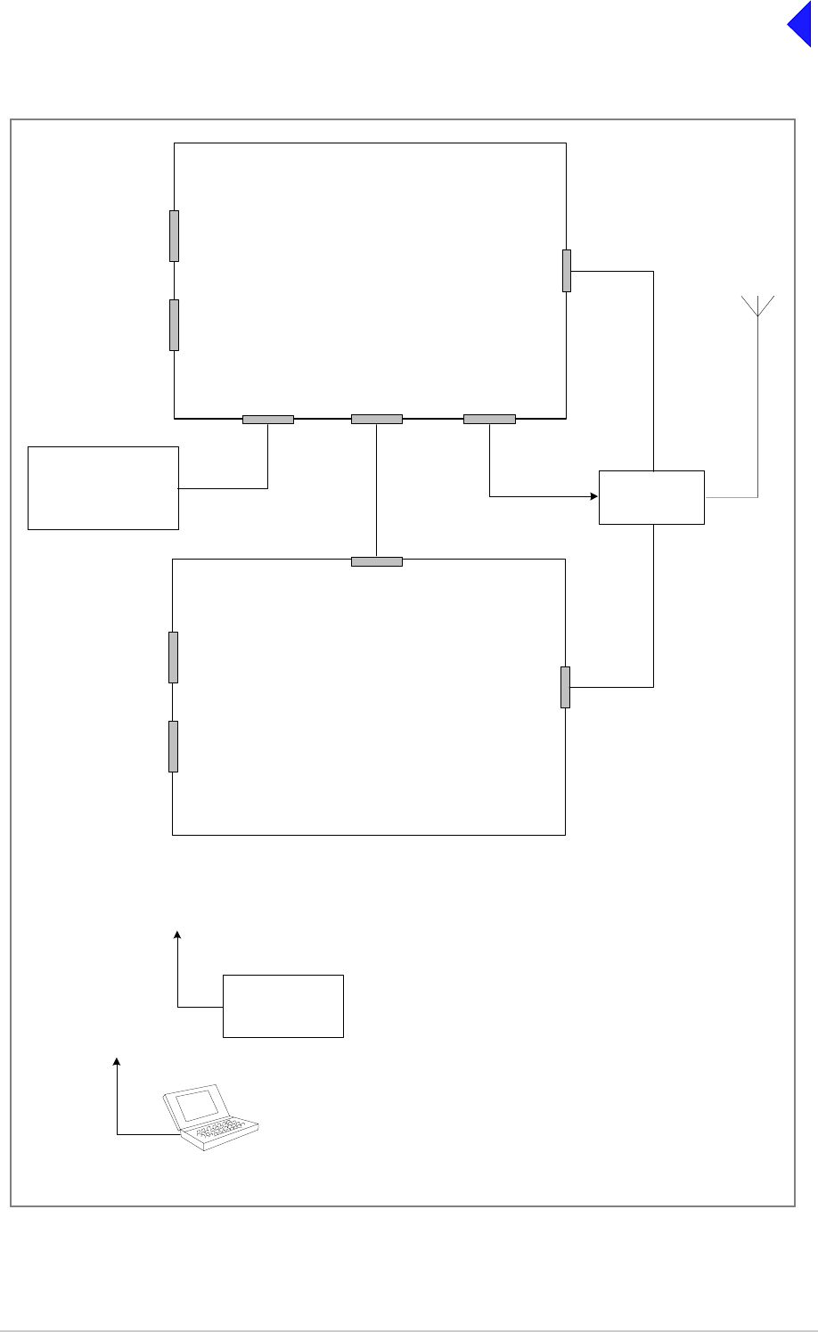
Fig 4 T6T Transmitter Mode 2 Configuration
Antenna
Connector
T6R Receiver
Antenna
Connector
T6T Transmitter
HDLC
Connector T1/E1
Connector Facilities
Connector
Reference
Connector
Microphone/Diagnostics
Connector
Reference
Connector
Headset/Diagnostics
Connector
T1/E1
Connector
Fast Antenna
Change-Over
Switch
Antenna c/o control
Mode 2
Network Computer
Laptop (or PC) required
only for maintenance
Connects to the
Microphone/Diagnostics
connector
Frequency Counter
required only for
maintenance
Connects to the
Reference connector
Control and data
Control and
data. 2 km
maximum
distance
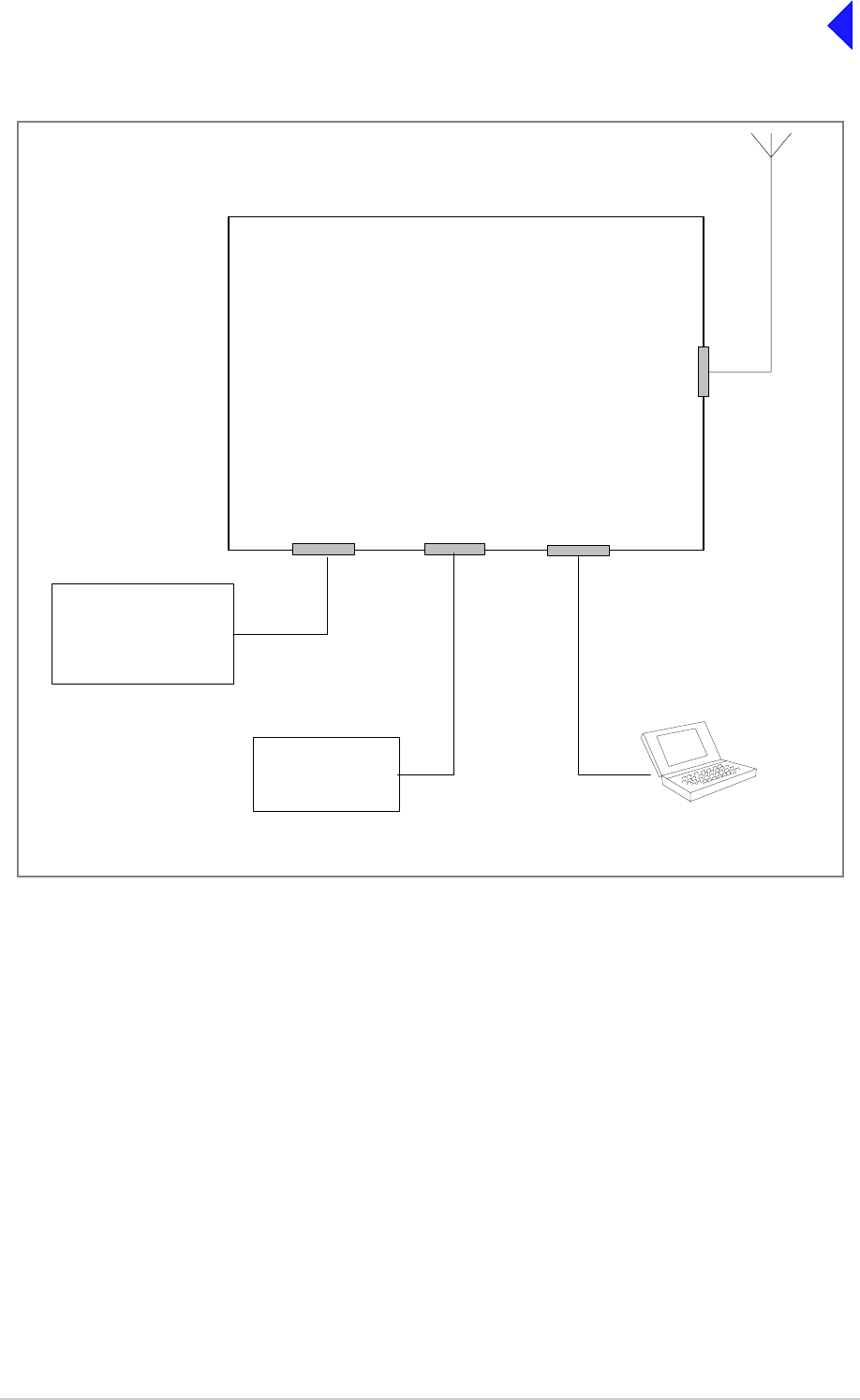
T6T VHF 100 W Transmitter Page 8 Installation
Back to Transmitter
Main Page
Fig 5 T6T Transmitter Mode 3 Configuration
Antenna
Connector
T6T Transmitter
T1/E1
Connector Reference
Connector Microphone/Diagnostics
Connector
Mode 3
Network Computer Control and data
Frequency Counter
required only for
maintenance
Laptop (or PC) required
only for maintenance
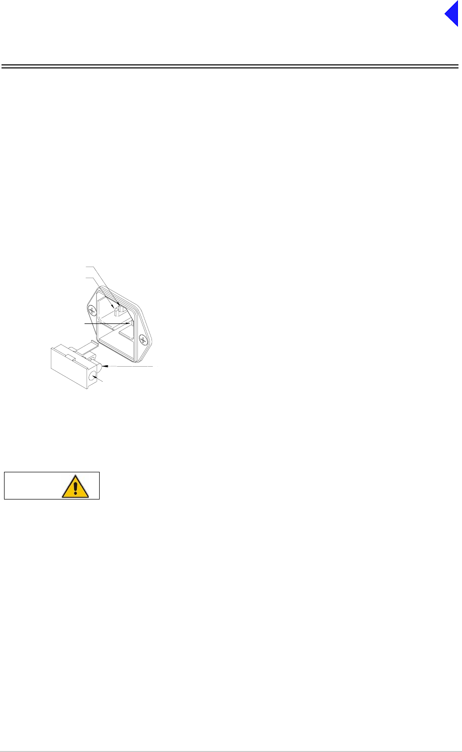
T6T VHF 100 W Transmitter Page 9 Installation
Back to Transmitter
Main Page
Installation Procedures
Initial Inspection of the Transmitter
On receipt of the transmitter, remove all transit packaging and check that there is no damage. If damage
is evident, contact Park Air immediately and retain the original transit packaging. One copy of the T6 User
Documentation CD (part number 31-36T62VCD) is normally supplied with the transmitter. This CD
includes the VFP software.
Fitting the Correct AC Input Fuses
The mains input fuses, F3 and F4, are an integral part of the rear panel ac connectors. The fuse type
must be correct for the local mains supply as detailed below.
Fitting a Radio into an Equipment Cabinet
It is essential that the chosen mechanical installation provides adequate support along the
depth (front to rear) of the unit. The transmitter must not be supported by the front panel;
doing so can cause damage.
The transmitter can be installed on telescopic slides, or on fixed runners, within a standard 483 mm
(19 inch) equipment cabinet. M4 tapped holes, each 10 mm deep (see Fig 6) are provided on each side
of the equipment to accept the slides. Details of suitable telescopic slides and fixed runners are available
from Park Air.
When fitted in the cabinet, the transmitter's front panel must be secured to the cabinet’s chassis using
four M6 x 16 mm screws and plastic washers.
FS2
Spare Fuse
Line
Neutral
Earth
For a mains input in the range 110 to 120 Vac, fuses
F3 and F4 should be rated T4A, 125V, UL.
For a mains input in the range 220 to 230 Vac, fuses
F3 and F4 should be rated T4A, 250V, IEC.
F3 and F4
Holder for spare
fuse (not supplied)
Caution Mechanical Support
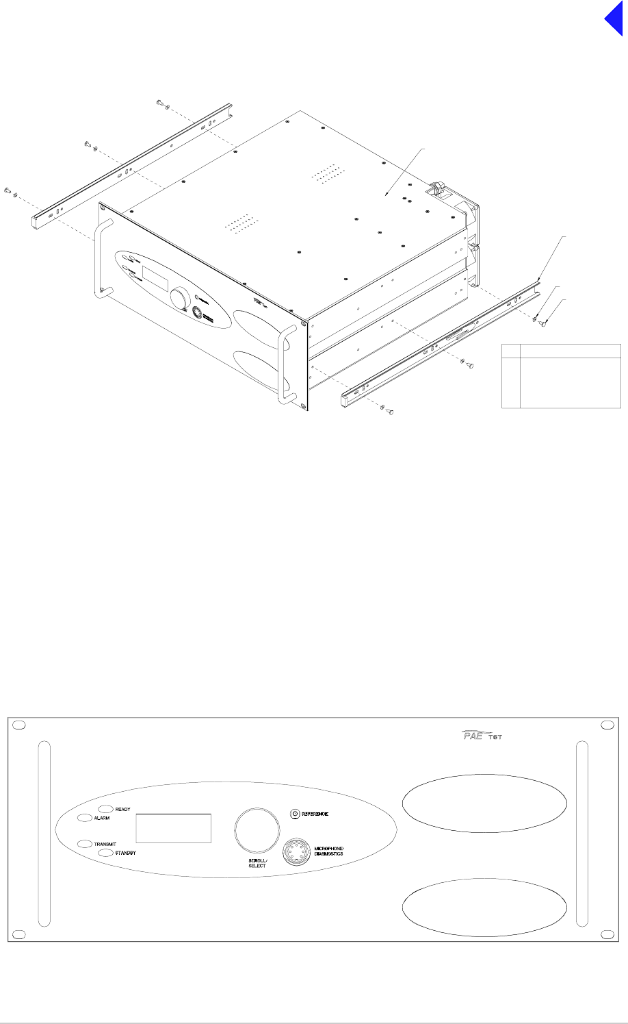
T6T VHF 100 W Transmitter Page 10 Installation
Back to Transmitter
Main Page
Fig 6 Slide Fittings
Make External Signal Connections
Making the external signal connections involves configuring the transmitter to suit its operational mode.
Illustrations showing various configurations are shown in Fig 1 to Fig 5; these figures should be used only
as a guide.
Front Panel Connectors
The front panel has two connectors; Microphone/Diagnostics and Reference connectors. These are
illustrated in Fig 7.
Fig 7 Front Panel
3
4
2
1
M4 x 8 mm Half Head Bolt
M4 Wavy Washer
Inner Slide
Transmitter
Description
4
3
2
1
Item

T6T VHF 100 W Transmitter Page 11 Installation
Back to Transmitter
Main Page
Microphone/Diagnostics Connector
The Microphone/Diagnostics connector is a self-locking 7-way DIN socket used for connecting a
microphone, microphone/headset or PC. The connector pin-out is detailed in Table 3.
Reference Connector
The Reference connector is an SMB plug used to monitor the radio’s reference frequency. It monitors
the frequency at a level of 100 mV (±50 mV) with less than -10 dBc harmonics.
Table 3 Microphone/Diagnostics Connector
Pin Number Signal Characteristic Usage
1 Microphone ground 0 V. Microphone/Headset
2 Transmit data RS232. 115200 baud, 8 data bits, 1 stop bit,
no parity, no handshaking. PC
3 Microphone PTT 0 V to PTT. Microphone/Headset
4 Receive data RS232. 115200 baud, 8 data bits, 1 stop bit,
no parity, no handshaking. PC
5 Sidetone – Microphone/Headset
6 Microphone input To ensure correct VOGAD operation, the
following microphone input levels are
required:
Passive setting: between 2 and 35 mV
Active setting: between 8 and 140 mV.
Microphone/Headset
7Ground 0V. PC
Pin-out of the Microphone/Diagnostics connector looking into
the mating face of the chassis mounted socket.
A suitable free socket is detailed in Table 2 on page 3.
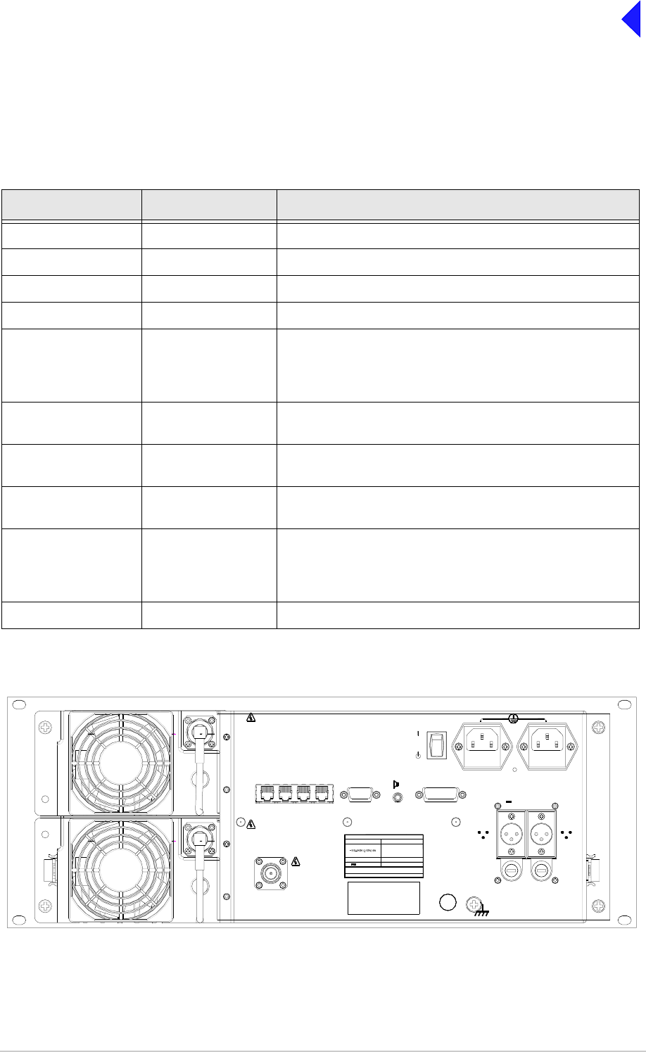
T6T VHF 100 W Transmitter Page 12 Installation
Back to Transmitter
Main Page
Rear Panel Connectors
The rear panel connectors are shown in Fig 8 and listed in Table 4. Select which connectors are going
to be used and then make connections as required.
Fig 8 Rear Panel (Connectors)
Table 4 Rear Panel Connector Usage
Connector Type Usage
AC supply 2 x IEC Terminating the ac input supply.
DC supply 2 x XLR 3-pin Terminating the dc input supply.
Antenna N-type Terminating the antenna feeder coaxial cable.
External speaker 3.5 mm stereo jack Connects an external loudspeaker for monitoring sidetone.
MARC 9-way D-type Used to connect to a MARC remote site equipment.
Used to connect a T6 controller or hub.
Used to terminate remote audio and PTT signals when a
remote site equipment or T6 controller is not used.
MARC audio RJ48 Used as an alternative to the MARC connector for terminating
remote audio and PTT signals.
MARC data RJ48 Used as an alternative to the MARC connector for terminating
data signals to and from a compatible data system.
Facilities 15-way D-type Provides a number of optional facilities that can be used as
required.
T1/E1 RJ48 Used for connecting the radio to a Mode 3 network computer,
connecting a transmitter and receiver together as a Mode 2
base station, or for connecting to a digital voice and data
network.
HLDC RJ48 Used to connect to a Mode 2 network computer.
RF VOLTAGES
DANGE R HIGH
ANTENNA
CONNECT
ANTENNA
BEFORE
USE
F15A 32V
110-240V T4A 250V IEC
110-120V T4A 125V UL
FUSE F1 / F2
FUSE F3 / F4
SEE INSTALLATION INSTRUCT IONS BEFORE
DISCONNECT SUP PLIES WHEN NOT IN USE
DC SUPPLY
CONNECT ING SUPPLIES
21.6-32V 28 A
RATINGS
POWER 800VA max
AC SUPPLY
48-62Hz
FUSE F2
FUSE F1
+
-
+
-
DC SUPPLIES
~ AC SUPPLIES FUSE F4FUSE F3
FACILITIES
SUPPLY
MARC
AUDIO
T1 / E1 HDLC DATA
MARC MARC
DANGER HIGH
RF VOLTAGES
USE
BEFORE
CONNECT
USE
DANGER HIGH
RF VOLTAGES
CONNECT
BEFORE
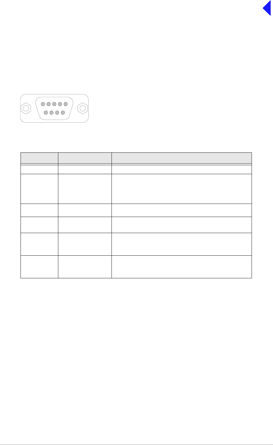
T6T VHF 100 W Transmitter Page 13 Installation
Back to Transmitter
Main Page
MARC Connector
The MARC connector is a 9-way D-type socket used to connect the transmitter to a MARC remote site
equipment, or it can also be used for normal remote operation.
As an alternative to using this connector, the RJ48 style MARC Audio and MARC Data connectors can
be used to provide the same functions.
The MARC connector pin-out is shown below and detailed in Table 5.
Note ...
The line level figures shown for the MARC connector are the limits when testing the transmitter using
a sine wave; the line level will be 10 dB above the line level setting. See the information supplied
under the heading ‘Line Level Setting’ in Operation.
Table 5 MARC Connector
Pin Number Signal Characteristic
1Ground 0V.
2
3Audio line in (+)
Audio line in (-)
Balanced 600 ohm, -20 to +20 dBm.
Phantom keying can be superimposed on the audio
lines. See Fig 10.
4 PTT input Remote PTT signal input. See Fig 9.
5 Output supply This output is between 21.6 and 32 Vdc (nominally
28 V) fused at 500 mA.
6
7
Data in (+)
Data in (-)
RS422 differential asynchronous data at 9600 baud,
8 data bits, 1 stop bit, no parity, no handshaking.
8
9
Data out (+)
Data out (-)
RS422 differential asynchronous data at 9600 baud,
8 data bits, 1 stop bit, no parity, no handshaking.
Pin-out of MARC connector looking into the mating face of the
chassis mounted socket.
A suitable free socket is detailed in Table 2 on page 3.
15
69
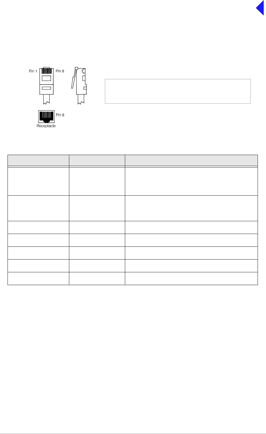
T6T VHF 100 W Transmitter Page 14 Installation
Back to Transmitter
Main Page
MARC Audio Connector
The MARC Audio connector is an 8-way RJ48 socket. It can be used as an alternative to the MARC
connector for audio and PTT connections. The connector pin-out is shown below and detailed in Table 6.
Note ...
The line level figures shown for the MARC Audio connector are the limits when testing the
transmitter using a sine wave; the line level will be 10 dB above the line level setting. See the
information supplied under the heading ‘Line Level Setting’ in Operation.
Table 6 MARC Audio Connector
Pin Number Signal Characteristic
1
2
Audio line in (-)
Audio line in (+)
Balanced 600 ohm, -20 to +20 dBm.
Phantom keying can be superimposed on the audio
lines. See Fig 10.
3 Fast antenna
change-over/PTT
(output)
Open collector NPN transistor grounding output,
200 mA max, configurable n/o or n/c.
4 Not used -
5 Not used -
6 PTT (input) Remote PTT signal input. See Fig 9.
7 Ground 0 V.
8 Not used -
Pin 1
RJ48 Plug
Numbering is shown looking from the top of the connector.
The top is being viewed when the lever is on the bottom.
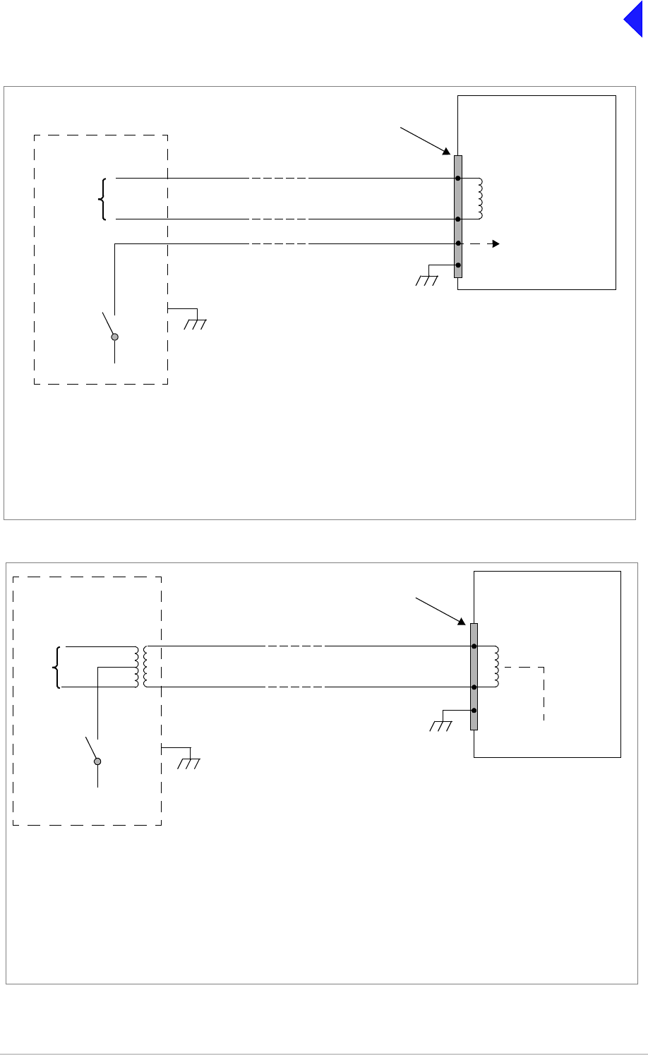
T6T VHF 100 W Transmitter Page 15 Installation
Back to Transmitter
Main Page
Fig 9 Remote Keying
Fig 10 Phantom Keying
T6T Transmitter
MARC Audio Connector
Audio is pins 1 and 2.
Audio line 1
Audio line 2
PTT Reference Voltage
(0 V, +14 V or -14 V)
Set from front panel
PTT
Switch
VPTT
The transmitter reference voltage (0 V, +14 V or -14 V) is selected from the Polarities screen:
❑PTT is active when VPTT differs from the transmitter reference voltage by more than ±10 V.
❑PTT is inactive when VPTT differs from the transmitter reference voltage by less than ±1 V.
❑Maximum value of VPTT is ±60 V with respect to transmitter reference voltage.
Example:
To use 0 V as the keying potential, VPTT = 0 V; set transmitter reference voltage to +14 V; set PTT In to STD.
Cross-Site Lines
Audio
Circuit
PTT input requires at least 1 mA to operate.
Input will draw no more than 6 mA.
PTT is pin 6
MARC Connector
Audio is pins 2 and 3.
PTT is pin 4
MARC or
MARC Audio
Connector
Control
Equipment Ground is pin 7.
Ground is pin 1.
T6T Transmitter
PTT
Switch
Reference Voltage
(0 V, +14 V or -14 V)
Set from front panel
V
PTT
To reduce the number of cross-site lines between the control site and the transmitter, phantom keying may be employed.
This method has the keying potential (VPTT) superimposed on the audio lines instead of using a separate line.
The transmitter reference voltage (0 V, +14 V or -14 V) is selected from the Polarities screen:
❑PTT is active when VPTT differs from the transmitter reference voltage by more than ±10 V.
❑PTT is inactive when VPTT differs from the transmitter reference voltage by less than ±1 V.
❑Maximum value of VPTT is ±60 V with respect to transmitter reference voltage.
Example:
To use 0 V as the keying potential, VPTT = 0 V; set transmitter reference voltage to +14 V; set PTT In to STD.
Audio lines with phantom keying
signal superimposed
PTT input requires at least 1 mA to operate.
Input will draw no more than 6 mA.
MARC Audio Connector
Audio is pins 1 and 2
MARC Connector
Audio is pins 2 and 3
MARC or
MARC Audio
Connector
Audio
Circuit
Control
Equipment
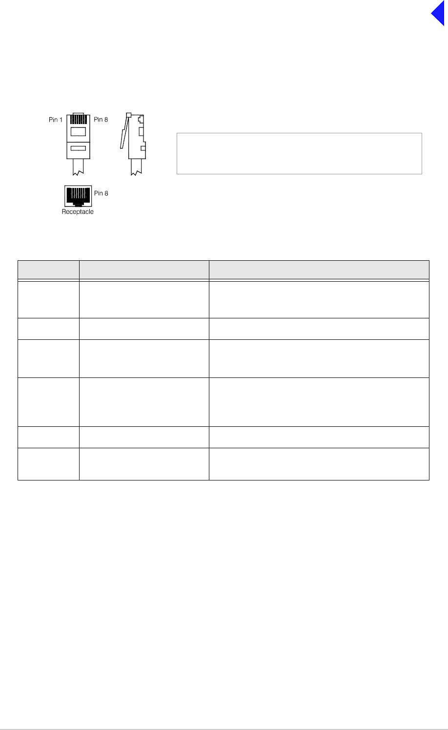
T6T VHF 100 W Transmitter Page 16 Installation
Back to Transmitter
Main Page
MARC Data Connector
The MARC Data connector is an 8-way RJ48 socket. It can be used as an alternative to the MARC
connector for data connections. The connector pin-out is shown below and detailed in Table 7.
Table 7 MARC RJ48 Data Connector
Pin Number Signal Characteristic
1
2
Data in (-)
Data in (+)
RS422 differential asynchronous data, 9600 baud,
8 data bits, 1 stop bit, no parity, no handshaking.
3 Not connected -
4
5
Data out (+)
Data out (-)
RS422 differential asynchronous data, 9600 baud,
8 data bits, 1 stop bit, no parity, no handshaking.
6 Remote supply ON/OFF 0 V to switch off.
Note: Rear panel switch must be in the ON position
for this function to operate.
7Ground 0V.
8 Output supply This output is between 21.6 and 32 Vdc (nominally
28 V) fused at 500 mA.
Pin 1
RJ48 Plug
Numbering is shown looking from the top of the connector.
The top is being viewed when the lever is on the bottom.
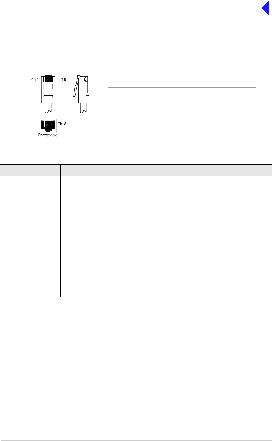
T6T VHF 100 W Transmitter Page 17 Installation
Back to Transmitter
Main Page
T1/E1 Connector
The T1/E1 connector is an 8-way RJ48 socket used for connecting to a Mode 3 network computer or
connecting a transmitter and receiver together when operating as a Mode 2 base station. The connector
pin-out is detailed in Table 8.
Table 8 T1/E1 Connector
Pin Signal Characteristic
1 RRing T1 - Balanced 100 ohm (±10%), 1.544 Mbits per second (±50 ppm), AMI/B8ZS Coding.
E1 - Balanced 120 ohm (±10%), 2.048 Mbits per second (±50 ppm), AMI/HDB3 Coding.
Protected with 28 V differential and common mode clamp and 1.25 A fuse in each line.
2RTip
3 Not connected -
4 TRing T1 - Balanced 100 ohm (±10%), 1.544 Mbits per second (±50 ppm), AMI/B8ZS Coding.
E1 - Balanced 120 ohm (±10%), 2.048 Mbits per second (±50 ppm), AMI/HDB3 Coding.
Protected with 28 V differential and common mode clamp and 1.25 A fuse in each line.
5TTip
6 Not connected -
7 Not connected -
8 Not connected -
Pin 1
RJ48 Plug
Numbering is shown looking from the top of the connector.
The top is being viewed when the lever is on the bottom.
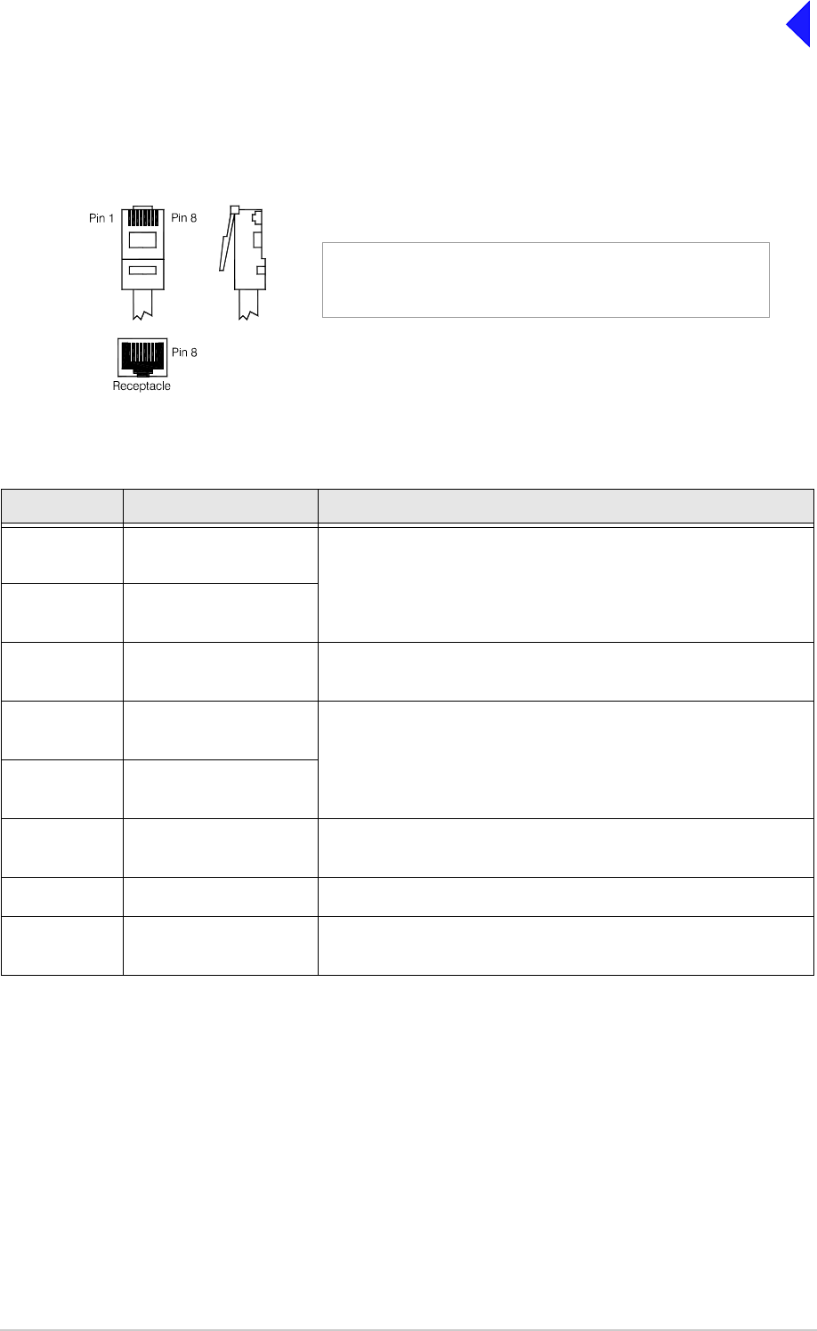
T6T VHF 100 W Transmitter Page 18 Installation
Back to Transmitter
Main Page
HDLC Connector
The HDLC connector is an 8-way RJ48 socket used for connecting to a Mode 2 network computer. The
connector pin-out is detailed in Table 9.
.
Table 9 HDLC Connector
Pin Signal Characteristic
1 HDLC RX A
(input) RS422 differential synchronous data, 128 kbytes per second
(±50 ppm).
2 HDLC RX B
(input)
3 HDLC CL A
(output) RS422 differential synchronous data, 128 kbytes per second
(±50 ppm).
4 HDLC TX B
(output) RS422 differential synchronous data, 128 kbytes per second
(±50 ppm).
5 HDLC TX A
(output)
6 HDLC CL B
(output) Pair to pin 3.
7Ground 0 V.
8 Output supply This output is between 21.6 and 32 Vdc (nominally 28 V) fused at
500 mA.
Pin 1
RJ48 Plug
Numbering is shown looking from the top of the connector.
The top is being viewed when the lever is on the bottom.

T6T VHF 100 W Transmitter Page 19 Installation
Back to Transmitter
Main Page
External Speaker
The External Speaker connector is a 3.5 mm stereo jack used for connecting an external speaker to the
transmitter to provide sidetone. This speaker should be a high impedance active type.
Table 10 External Speaker
Pin Signal Characteristic
Tip Speaker drive (output) 0 to 3 V pk-pk. Connected directly to Ring.
Ring Speaker drive (output) 0 to 3 V pk-pk. Connected directly to Tip.
Sleeve Ground 0 V.

T6T VHF 100 W Transmitter Page 20 Installation
Back to Transmitter
Main Page
Facilities Connector
The Facilities connector is a 15-way D-type filtered socket used for connecting to associated parts of a
system. The connector pin-out is detailed in Table 11.
Table 11 Facilities Connector
Pin Number Signal Characteristic
1Ground 0V.
2 E-BIT (input) An external BIT input that connects from any ancillary equipment
having a compatible BIT alarm output.
When this input is active, the transmitter’s front panel Alarm indicator
flashes and an E-BIT message is displayed on the display. The input is
TTL having a 4.7 kohm pull-up resistor to 5 V. The input is
configurable from the front panel to be active high or low.
3 PTT output Grounding solid state relay. +60 to -60 V, ac or dc, 100 mA max,
configurable n/o or n/c. Activated 35 ms (±1 ms) before the start of the
power ramp up to allow for the antenna relay pull-in time.
4 External VSWR input Used to indicate an external VSWR fault. TTL input with 4.7 kohm pull-
up to 5 V. Configurable active high or low.
5
6
Antenna change-over
(output)
Antenna change-over
common (output)
Solid state relay linked to pin 6. See Fig 11 for further detail.
Solid state relay linked to pin 5.
7 Not used -
8Ground 0 V.
9 Output supply This output is between 21.6 and 32 Vdc (nominally 28 V) fused at
500 mA.
10 Inhibit (input) Active signal prevents the transmitter keying. TTL with 4.7 kohm pull-
up to 5 V. Configurable active high or low.
11 BIT interruptive test
(input) Active signal initiates a BIT test. TTL with 4.7 kohm pull-up to 5 V.
Configurable active high or low. Must be asserted for >300 ms.
12 Not used -
13 Ready (output) An output that is active when the radio is ready to transmit and no
faults are detected. Open collector NPN transistor grounding output,
200 mA max, configurable n/o or n/c.
14 Tape (output) An audio output for connection to a recording system. 0 dBm fixed
output into 600 ohm for 90% modulation depth.
15 Reserved (output) Do not connect to pin 15 unless advised to do so by Park Air.
18
915
Pin-out of Facilities connector looking into the mating face of
the chassis mounted socket.
A suitable free socket is detailed in Table 2 on page 3.
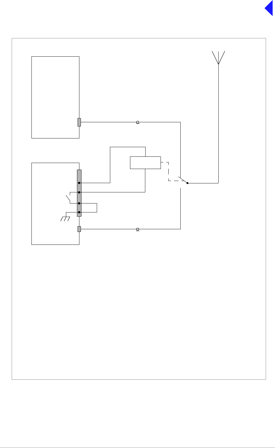
T6T VHF 100 W Transmitter Page 21 Installation
Back to Transmitter
Main Page
Fig 11 Example: Using the Antenna Change-over Output
T6T Transmitter
6
5
Facilities
Connector
Antenna
T6T Transmitter
Facilities
Connector
Antenna
9
28 Vdc (nominal)
Control
(Main)
(Standby)
Antenna
Main/Standby
Transmit Relay
Example
This example shows the Antenna Change-over Output configured to control the antenna switching between main
and standby transmitters. The potential on Facilities connector pin 6 is switched through to pin 5 when the standby
transmitter is keyed; in this example, pin 6 is linked to ground. This energizes the Main/Standby Transmit Relay to
route the standby transmitter to the antenna.
Other Configurations
The antenna change-over output can be configured in other ways to suit the user’s requirement subject to:
❑Pin 6 can be any potential between -60 and +60 Vac, or dc.
❑The maximum current drawn must not exceed 100 mA.
❑The output at pin 5 is configurable normally open or normally closed from the Polarities screen.
❑The internal solid state switch activates 35 ms before the start of the power ramp to allow for the antenna
relay pull-in time.
8
Solid State
Relay
Link

T6T VHF 100 W Transmitter Page 22 Installation
Back to Transmitter
Main Page
Chassis Stud Connection
A chassis stud is fitted to the transmitter's rear panel. This stud is used to connect the
equipment to the equipment cabinet, or to the user's system earth point. The stud must not
be used as the safety earth.
In order not to compromise the transmitter’s Electromagnetic Compatibility (EMC) the chassis stud,
marked and fitted to the rear panel must be connected to the equipment cabinet (if a cabinet is being
used) or to the user's system earth point. The connection should be made using a single tri-rated, green-
and-yellow cable having a cross-sectional area of 2.5 mm2. The cable should have CSA and UL1015
approval, and be connected to the chassis stud through an M6 eyelet (for example, Park Air part number
20-08010103).
Failure to comply with this instruction could result in non-compliance with the European
Commission EMC Directive 89/336/EEC.
Connect the Antenna
The antenna connector is an N-type socket suitable for connecting a 50 ohm antenna.
Connect the DC Input Supply
The transmitter operates from either an ac, or a dc input supply. When both ac and dc are connected,
operation from the ac supply takes priority; automatic change-over to the dc supply occurs if the ac
supply fails. On restoration of the ac supply, the equipment reverts to ac operation.
The dc input supply connectors (see Fig 12) are fitted to the transmitter rear panel. The recommended
minimum rating of the dc supply cables is: 2-core having a cross-sectional area of 1.5 mm2 per core. The
supply cables should be fitted with XLR 3-pin connectors (Park Air part number 20-01030106).
Fig 12 DC Connectors
WARNING Chassis Earth
Positive Negative
Not used
Pin-out of DC connector looking
into the mating face of the chassis
mounted socket.
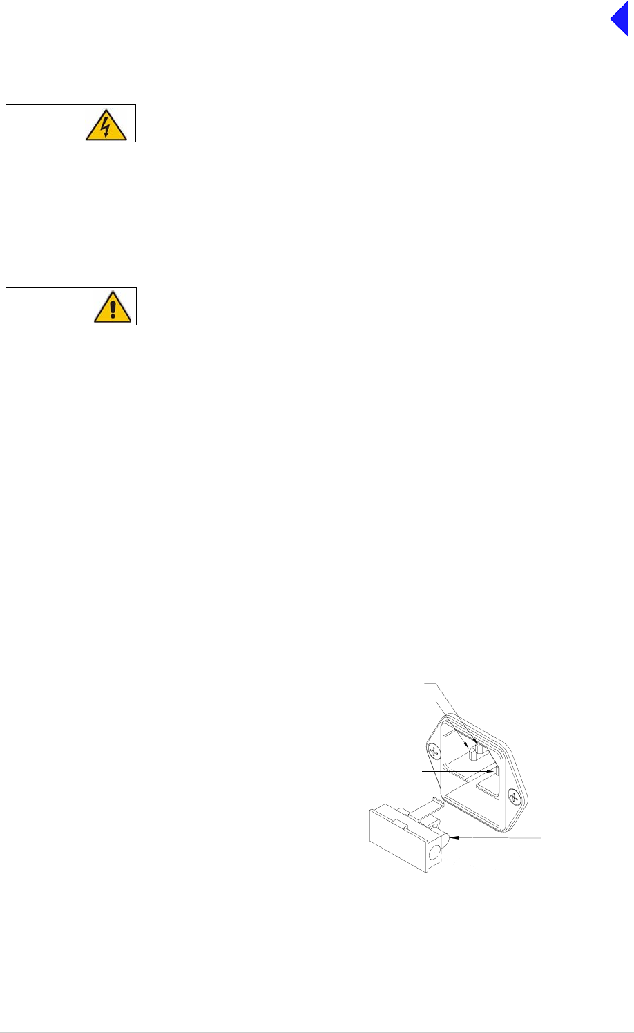
T6T VHF 100 W Transmitter Page 23 Installation
Back to Transmitter
Main Page
Connect the AC Input Supply
The equipment is permanently connected to the mains supply when the mains connector is
attached. Switching the rear panel Power switch to off does not isolate all internal circuits
from the mains supply. For this reason, a mains isolating switch should be fitted close to,
and easily accessible from, the transmitter's position. The isolation switch should isolate
both live and neutral supplies, be clearly labelled, and adequately rated to protect the
equipment.
This equipment must be earthed. The earth terminal of the ac connector should be used as
the safety earth.
Two ac input connectors are fitted to the transmitter rear panel. The cables used to connect between the
equipment and the ac power source should be 3-core (to IEC 227) rated 250 Vac at 8 amps, and have a
minimum cross-sectional area of 1.0 mm2 per core. Park Air recommends the use of polyvinyl chloride
(PVC) insulated cable. The cable must be fitted with the IEC approved equipment connector and conform
to the following specification:
❑If PVC insulated, be not lighter than ordinary polyvinyl chloride sheathed flexible cord according
to IEC publication 227 (designation H05 VV-F, or H05 VVH2-F).
❑If rubber insulated, be of synthetic rubber and not lighter than ordinary tough rubber-sheathed
flexible cord according to IEC publication 245 titled ‘Rubber Insulated Cables of Rated Voltages
up to and Including 450/750 V (designation H05 RR-F)’.
The T6T 100 W transmitter is a Class 1 equipment. The ac supply cables should have a green-and-
yellow protective earthing conductor electrically connected to the protective earthing terminal of the
equipment connector and the mains plug. Park Air recommends the ac supply cable is colour coded in
accordance with the electrical appliance (colour code) regulations for the UK. That is:
WARNING Dangerous Voltages
WARNING Earth Connection
FS2
Spare Fuse
Line
Neutral
Earth
❑The core coloured green-and-yellow must be
connected to the terminal in the plug that is
marked with the letter E or by the earth symbol
or coloured green-and-yellow.
❑The core coloured blue must be connected to
the terminal that is marked with the letter N or
coloured black.
❑The core coloured brown must be connected to
the terminal that is marked with the letter L or
coloured red. F3 and F4
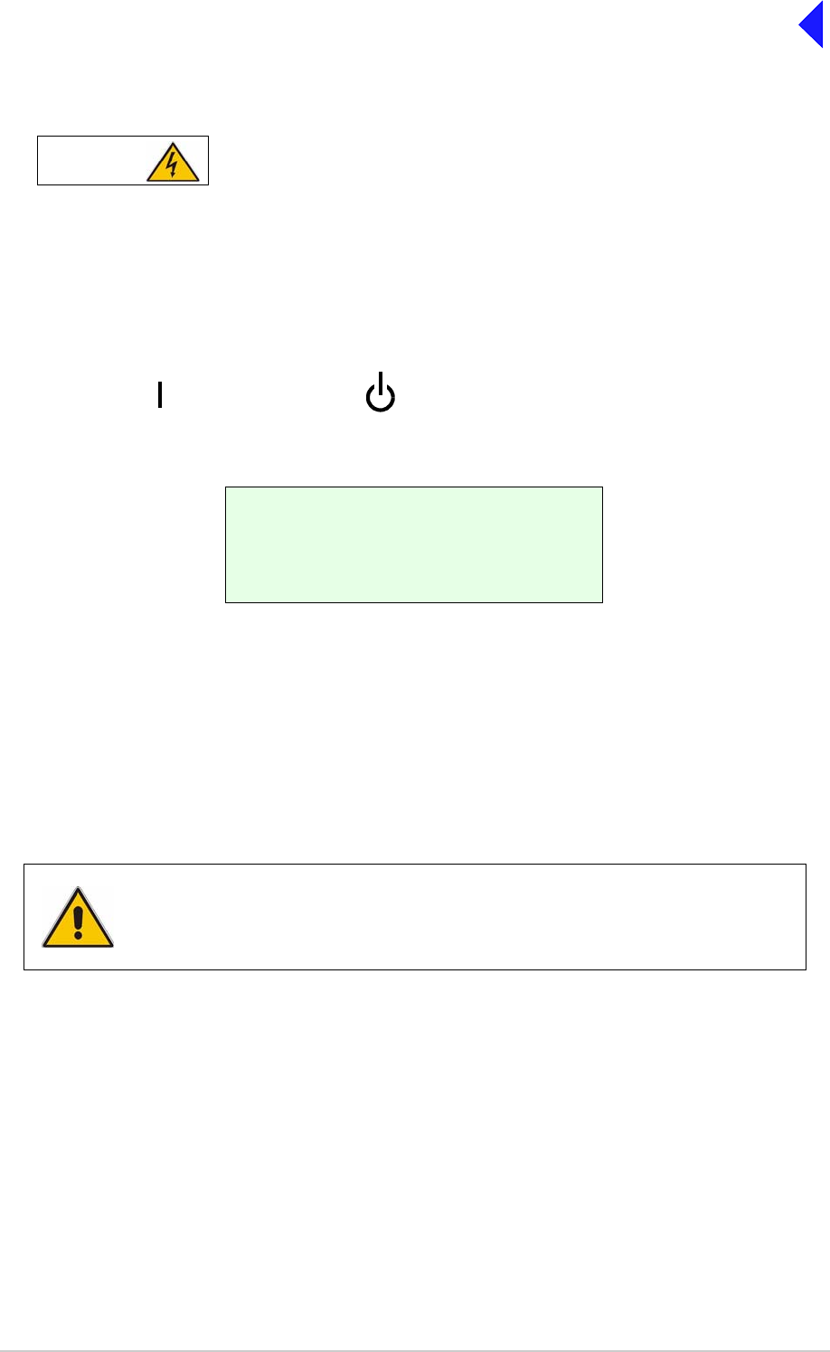
T6T VHF 100 W Transmitter Page 24 Installation
Back to Transmitter
Main Page
Switching On
When the Power switch is set to the Standby position, dangerous voltages are still present
in the transmitter's internal power supply circuitry. To ensure safe working, the transmitter
must be isolated from the ac and dc input supplies.
When installation is complete, the transmitter should be switched on at the rear panel 2-way rocker
Power switch. The Power switch is used to switch on, and switch off, power to the transmitter's circuitry
but does not remove power from the radio.
Under normal circumstances this screen is displayed for a few seconds when the radio is switched on.
The bottom row begins empty and dots are added as the initialisation progresses. When the initialisation
is complete the Main Screen is displayed.
Setting Up
When installation has been successfully completed the transmitter must be set up using the front panel
controls or the VFP.
Setting up is detailed in the Operation section of this documentation.
T 6 D i g i t a l R a d i o
( c ) 2 0 0 3 P a r k A i r
I n i t i a l i s i n g . . . .
. . . . . . . . . . . . . . .
WARNING Dangerous Voltages
= Standby= On
When setting up the transmitter, pay particular attention to the Polarities of any
functions that have been hardwired during installation. For example, the polarity of
the PTT input and the polarity and configuration of the Antenna Change-over
output. Failure to select the correct settings will result in incorrect operation.

Back to Transmitter
Main Page
Maintenance
This topic gives scheduled maintenance procedures, details module replacement, and
describes how to use the Virtual Front Panel (VFP).

T6T VHF 100 W Transmitter Page 2 Maintenance
Back to Transmitter
Main Page
Introduction
This section gives the scheduled and unscheduled maintenance procedures for the T6T 100 W
transmitter and shows how to use the Virtual Front Panel (VFP).
Configuration
T6 radios are configured in respect of hardware and software.
Hardware Configuration
The radio’s hardware configuration is identified by the
modification level. A modification label is fitted to the radio’s
rear panel showing the model of radio, the radio’s part number
and the radio’s serial number.
The modification (Mod) record shows the configuration status.
In the example shown, the radio is at Mod strike 8.
Modification Label
Software Configuration
A white label fitted to the top
cover lists the radio’s software
configuration.
In this example there are three
fills: AM-Voice, Mode 2 and
Mode 3.
Software Configuration Label
Replacement Modules
To ensure compatibility when replacing a radio or a module, the configuration should be the same (see
the previous headings: Hardware and Software Configuration).
Spare modules received from Park Air are supplied with a Spares Instruction that details the
configuration of the module and any special instructions. If in any doubt regarding the suitability of spare
modules contact Park Air Customer Support.
Scheduled Maintenance A scheduled maintenance procedure is given on page 3. Park Air
recommends that this task be completed every twelve months.
Unscheduled Maintenance Normally, the T6 transmitter is considered a Line Replaceable Unit
(LRU) and should be replaced with a serviceable spare if a fault
occurs. The faulty transmitter should then be returned to Park Air
for repair.
In certain circumstances, Park Air Customer Support may suggest
that the user change one of the transmitter modules. Dismantling
and assembly instructions are therefore given under the heading
Unscheduled Maintenance starting on page 7.
Using the VFP Operating parameters can be set from the transmitter front panel,
or by using the VFP. Some additional functions are available from
the VFP. See page 22.
T6T100
B63100HS/NB
2K1234
Software Configuration
Part Order No. B63100HS/NB
Software Mode Part No.
Fill 1 AM_VOICE 65-00000465
Fill 2 2 65-00000466
Fill 3 3 65-00000467
Fill 4
2K1234

T6T VHF 100 W Transmitter Page 3 Maintenance
Back to Transmitter
Main Page
Scheduled Maintenance
Park Air recommends that scheduled maintenance is carried out at twelve-monthly intervals. Scheduled
maintenance comprises the following checks:
Cleaning and Checking Security of Connectors
Remove all dust and dirt from the equipment exterior using a lint-free cloth and camel hair brush. Check
all external connections are secure and free from damage.
Setting the Transmitter Internal Reference Frequency
To set the transmitter internal reference frequency, use the following procedure. Note that references to
the switch in the procedure mean the Scroll/Select switch.
(6) Turn the switch clockwise until Exit is highlighted, then press the switch. You are returned to the
Main screen.
(7) Disconnect the frequency counter.
Number Check Tools/Test Equipment Required
1 Ensure the equipment is clean and that external
connectors are securely fitted. Camel hair brush/clean lint-free
cloths
2 Check and reset (if required) the transmitter’s
internal frequency reference. VHF frequency counter
3 Perform a BIT interruptive test.
4 Perform an ac and dc change-over check (if both
supplies are connected).
Control Screen
Settings Screen
F r e q u e n c y
C h a n n e l
S e t t i n g s
E x i t
B a n d E d g e s
R e f F r e q 5 0 . 0 %
B a c k l i g h t 0 3 0 s
E x i t < < > >
(1) Ensure the transmitter does not have
an offset.
(2) Connect a frequency counter to the
front panel Reference connector.
(3) From the Main screen, press the switch
to display the Control screen. Turn the
switch until Settings is highlighted.
Press the switch.
(4) Ensure the Settings screen is
displayed. Turn the switch until Ref
Freq is highlighted, then press the
switch.
(5) With Ref Freq selected turn the switch
clockwise or anti-clockwise until the
frequency counter reads
20.950000 MHz ±10 Hz, then press the
switch.

T6T VHF 100 W Transmitter Page 4 Maintenance
Back to Transmitter
Main Page
(8) If not using 5-carrier offset, refer to AM-Voice Mode Settings Screen in the Operation section of
this document and set to the required offset.
(9) If 5-carrier offset is required, restore the carrier offset using the following routine:
❑Connect a 50 ohm frequency counter, through a 60 dB attenuator, to the transmitter rear
panel Antenna connector (see Fig 5 for location of the Antenna connector)
❑Refer to AM-Voice Mode Settings Screen in the Operation section of this document and set
the desired 5-carrier offset
❑Refer to Changing the Transmitter Operating Frequency in the Operation section and set the
transmitter to the nearest 25 kHz channel frequency. For example, if the required frequency
is 124.504 (+4 kHz offset), set the transmitter to 124.500 MHz
❑Key the transmitter and adjust the reference frequency, using the front panel Scroll/Select
switch, until the frequency counter displays the required operating frequency. For example
124.504 MHz
❑When the frequency counter displays the exact operating frequency, press the Scroll/Select
switch and stop keying the transmitter
❑Disconnect the test equipment and reconnect the antenna.

T6T VHF 100 W Transmitter Page 5 Maintenance
Back to Transmitter
Main Page
To Initiate a BIT Test
An interruptive BIT test cannot be initiated in Mode 2 or Mode 3.
(1) From the Main screen, press the switch to
display the Control screen. Turn the switch
until BIT is highlighted. Press the switch.
(2) Ensure the BIT menu is displayed. Turn
the switch until BIT Initiate is highlighted.
Press the switch.
(3) During the test, which takes approximately
two seconds, the Testing screen is
displayed.
(4) After the test, either a Pass or Fail screen
is displayed. Selecting OK takes the user
back to the BIT screen.
(5) If fail is displayed, scroll through the screen
to check the cause of the failure.
During an interruptive BIT test, the transmitter radiates modulated carrier waves at the set power.
Users should therefore obtain the necessary authority before initiating a test.
If the test is to be carried out with the antenna disconnected, ensure a load is fitted to the
transmitter’s Antenna connector.
In order to test the line input stages, an internally generated 1 kHz tone is injected into the line input
circuit. Any other audio present on the line input will cause the test to be inaccurate. Therefore the
transmitter MUST NOT be keyed during the test.
B I T
S / W C o n f i g
S t a n d b y
E x i t < <
B I T I n i t i a t e
E T I 0 0 0 0 0 : 0 0 h r s
A C S u p p l y O N
E x i t > >
T e s t i n g
P l e a s e W a i t
T e s t S t a t u s
P A S S
O K
T e s t S t a t u s
F A I L
O K

T6T VHF 100 W Transmitter Page 6 Maintenance
Back to Transmitter
Main Page
AC and DC Change-over Check
If both ac and dc input supplies are connected to the transmitter, carry out the following check:
(1) Confirm that both ac and dc supplies are connected to the transmitter. Ensure that the rear panel
Power switch is set to the I (on) position.
(2) Confirm that the front panel Ready indicator is lit, the LCD is illuminated, and the transmitter is
operational.
(3) Switch off the ac supply from its source.
(4) Check that the transmitter continues to operate correctly from the dc supply. If accessed, the
front panel BIT screen will show AC Supply as off, and DC Supply as on. The value of the dc
supply is also shown.
T6T VHF 100 W Transmitter Page 7 Maintenance
Back to Transmitter
Main Page
Unscheduled Maintenance
The instructions given in this section involve connecting dangerous voltages to the
transmitter. Maintenance should be carried out only by suitably qualified personnel.
When an ac supply is connected, dangerous voltages are present within the transmitter. Care
must be taken by personnel to avoid accidental contact with exposed circuitry during
maintenance or alignment procedures.
When the Power switch is set to the Standby position, dangerous voltages are still present
in the transmitter's internal power supply circuitry. To ensure safe working, the ac and dc
input supplies must be disconnected from the transmitter.
The antenna used with the transmitter must be installed such that the resultant radiated field
strength is below 10 W/m² in areas normally accessible to personnel.
The T6 transmitter circuitry contains Electrostatic Sensitive Devices (ESSDs). Personnel
must be aware of the precautions necessary to prevent damage to such devices.
Changes or modifications made to this equipment that are not expressly approved by
Park Air, or parties authorized by Park Air, could void the user’s authority to operate the
equipment.
When carrying out repairs to the PA module, care must be taken not to damage the gasket.
If the strips become damaged, they must be replaced. Failure to comply with this instruction
may compromise the transmitter Electromagnetic Compatibility (EMC) and breach European
Commission regulations.
When screws are inserted into the transmitter PA casting care must be taken not to exceed
a torque of 6 Ibs/inch when tightening. This applies when replacing the top and bottom
covers and during the refitting of the PA modules.
WARNING Dangerous Voltages
WARNING Antenna Radiation
Caution ESSDs
Caution Unauthorized Modifications
Caution Repairs
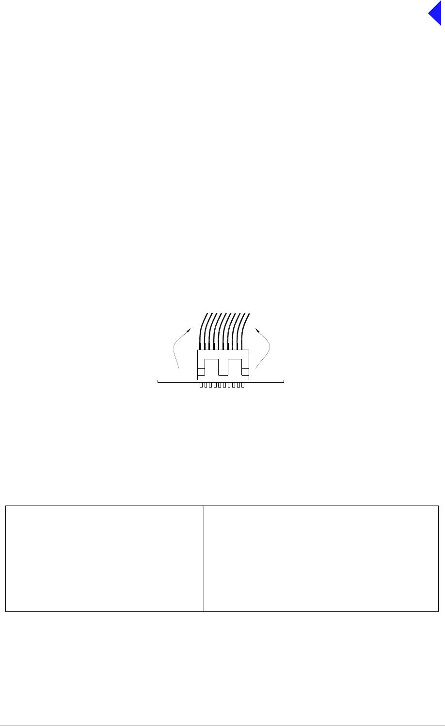
T6T VHF 100 W Transmitter Page 8 Maintenance
Back to Transmitter
Main Page
Introduction
This document provides the user with detailed instructions on the removal and replacement of modules
and assemblies. When removing or refitting modules, observe antistatic handling precautions. Do not
change any potentiometer (or link) settings unless detailed in these instructions. Potentiometers have
been set using specialist equipment.
Molex KK Connectors
The transmitter uses the following Molex KK connectors:
❑CN2 on the PA Control module
❑CN7 and CN6 on the PSU Regulator module.
To remove KK type connectors:
❑Free the locking mechanism on the connector by moving one side of the connector up, then move
the other side up (see the following diagram). The upward motion should only be as far as needed
to free the locking mechanism
❑DO NOT pull the cable to free the connector
❑Note that KK type connectors are designed to be removed in this manner to free the locking
mechanism. Do not use this procedure with non-KK type connectors as damage to the connector
may occur.
Tools, Materials and Test Equipment Required
The following tools, materials and test equipment should be made available to complete the maintenance
tasks described in this section.
❑Personal Computer (PC)
❑General Purpose Tool Kit (including
a 1.5 mm Allen key)
❑5 mm Nut Spinner
❑Camel Hair Brush
❑Clean Lint-free Cloths
❑Frequency Counter
❑Power Meter
❑Dummy Load
❑PC to Radio Interconnection Lead
(Park Air part number 17E12600001)
❑SMB to BNC Lead for Reference Frequency
(Park Air part number 17K11000004)
Lift 2Lift 1
PCB
T6T VHF 100 W Transmitter Page 9 Maintenance
Back to Transmitter
Main Page
Top and Bottom Covers
One of the top cover screws is covered with a warranty label that should not be tampered with unless
Park Air Customer Support has advised otherwise. When authorisation has been made the following
procedures should be followed.
To remove the top cover, locate and unscrew the 19 countersunk screws securing the top cover to the
mainframe. Access can then be gained to the Processor module and PSU Regulation module.
To remove the bottom cover, locate and unscrew the 15 countersunk screws securing the bottom cover
to the mainframe. Access can then be gained to the PA Control module.
The following modules require both top and bottom covers to be removed:
❑Power Supply modules
❑Combiner BIT module
❑PA modules
❑Front Panel assembly PCB.
Removing and Refitting the Processor Module
The Processor module is located as shown in Fig 5. A module removal diagram is shown in Fig 8.
Dangerous voltages are present within the transmitter. Care must be taken by personnel to
avoid accidental contact with exposed circuitry when the covers are removed and power is
applied to the radio.
Removal
Before attempting to remove the Processor module, and if possible, save the radio settings. Connect a
PC with the VFP software loaded to the radio using the PC to Radio Interconnection Lead (Park Air part
number 17E12600001). With the VFP software active, upload the radio settings to a specified file.
Ensure that the transmitter is isolated from the ac and dc input supplies. Then proceed as follows:
(1) Unscrew the 19 countersunk screws and remove the transmitter top cover.
(2) Locate the Processor module and disconnect the following connectors (Fig 8):
❑CN1 50-way connector (50-way ribbon cable from PA Control module CN1)
❑CN3 14-way connector (14-way ribbon cable from PSU Regulator module CN4)
❑CN4 34-way connector (34-way ribbon cable from Front Panel module CN1).
(3) Gain access to the rear of the transmitter. Using a 5 mm nut spinner tool, remove the four
screwloc 8 mm-4-40 UNC stud spacers that secure the Processor module interface connectors
CN5 and CN6 to the rear panel.
(4) Remove the seven M3 x 8 mm screws that secure the module to the transmitter mainframe.
(5) Remove the module from the chassis.
WARNING Dangerous Voltages
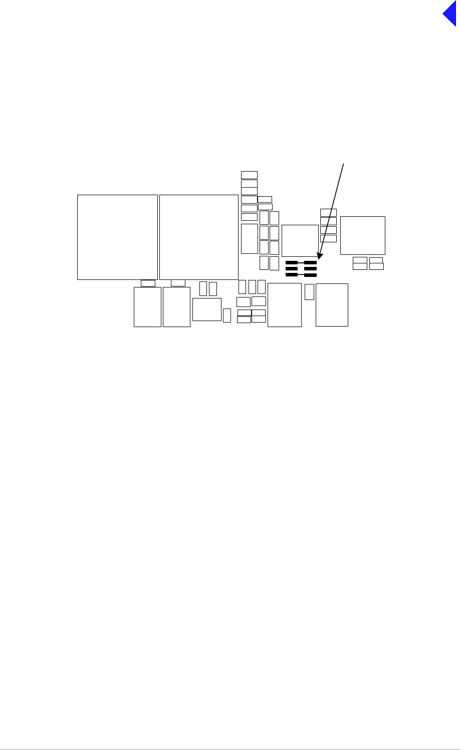
T6T VHF 100 W Transmitter Page 10 Maintenance
Back to Transmitter
Main Page
Refitting
To refit the Processor module, proceed as follows:
(1) Place the module in position. Ensure no wires are trapped by the module. Ensure jumper J2 on
the module is set to ‘T’ for transmitter (see Fig 1).
Fig 1 Processor Module JP2 Location
(2) Ensure the module interface connectors CN5 and CN6 are located correctly and are aligned with
the screw holes in the rear panel. Fit the four screwloc 8 mm-4-40 UNC screws and wavy
washers but leave them loose.
(3) Fit the seven M3 x 8 mm screws that secure the module to the transmitter mainframe, but leave
them loose.
(4) Using a 5 mm nut spinner tool, tighten the four screwloc 8 mm-4-40 UNC screws and wavy
washers that secure the connectors; then tighten the seven M3 x 8 mm screws that secure the
module to the transmitter mainframe.
(5) Refit the following connectors to the module:
❑CN1 50-way connector (50-way ribbon cable from PA Control module CN1)
❑CN3 14-way connector (14-way ribbon cable from PSU Regulator module CN4)
❑CN4 34-way connector (34-way ribbon cable from Front Panel module CN1).
(6) Re-establish the ac and/or dc supplies.
(7) Switch power on at the radio using the rear mounted Power switch.
(8) Ensure the front panel Ready indicator is lit and the Alarm indicator is unlit.
(9) If a new module has been fitted, connect the VFP PC to the radio using the PC to Radio
Interconnection Lead, Park Air part number 17E12600001 (if not already connected). Note that
any module sent from Park Air as a spare for a particular radio will be programmed with
compatible operating and Fill software. Park Air keeps records of module software in all radios
supplied. Care must be taken when using a module removed from another radio as this module
may not have compatible software.
(10) Download the saved radio settings from file using the VFP. Alternatively the settings can be
edited by hand as described in the Operation section of this document. Once entered, ensure the
required settings appear in the VFP screen.
IC25
T2 C84
TS7
T3
IC27
JP2
Shown set for
transmitter
T
T
R/TR
R/TR
IC21
IC20IC19
IC38

T6T VHF 100 W Transmitter Page 11 Maintenance
Back to Transmitter
Main Page
(11) Carry out the Calibrate routine using the Virtual Front Panel (VFP), as detailed in the procedure
To Calibrate the Transmitter on page 26.
(12) Carry out a BIT interruptive test as detailed in the procedure To Initiate a BIT Test on page 5.
(13) Set the transmitter internal reference frequency by carrying out the procedure detailed on
page 3.
(14) Set the rear panel Power switch to Standby and remove the VFP connector. Isolate the
transmitter from the ac and/or dc supplies.
(15) Refit the transmitter top cover. The transmitter can now be returned to service.
Removing and Refitting the PSU Regulator Module
The PSU Regulation module is located as shown in Fig 5. A module removal diagram is shown in Fig 9.
Dangerous voltages are present within the transmitter. Care must be taken by personnel to
avoid accidental contact with exposed circuitry when the covers are removed and power is
applied to the radio.
Removal
Before attempting to remove the PSU Regulation module, ensure that the transmitter is isolated from the
ac and dc input supplies. Then proceed as follows:
(1) Unscrew the 19 countersunk screws and remove the transmitter top cover.
(2) Locate the PSU Regulation module and remove the three M3 x 8 mm captive washer screws that
secure the module to the transmitter mainframe.
(3) Carefully raise the module to gain access to the module connectors.
(4) Disconnect the following connectors:
❑CN5 10-way connector (10-way ribbon cable to PA Control module CN6)
❑CN6 6-way connector (6-way loom to Combiner BIT module CN12)
❑CN4 14-way connector (14-way ribbon cable to Processor module CN3)
❑CN3 3-way connector (part of loom to Combiner BIT module CN7)
❑CN7 3-way connector (3-wire loom to rear panel On/Off switch)
❑CN2 2-way connector (part of loom to Combiner BIT module CN7)
❑CN1 4-way connector (part of loom to Combiner BIT module CN7)
(5) Remove the module from the chassis.
WARNING Dangerous Voltages

T6T VHF 100 W Transmitter Page 12 Maintenance
Back to Transmitter
Main Page
Refitting
To refit the PSU Regulator module, proceed as follows:
(1) While holding the module in position, connect the following connectors:
❑CN1 4-way connector (part of loom to Combiner BIT module CN7)
❑CN2 2-way connector (part of loom to Combiner BIT module CN7)
❑CN7 3-way connector (3-wire loom to rear panel On/Off switch)
❑CN3 3-way connector (part of loom to Combiner BIT module CN7)
❑CN4 14-way connector (14-way ribbon cable to Processor module CN3)
❑CN6 6-way connector (6-way loom to Combiner BIT module CN12)
❑CN5 10-way connector (10-way ribbon cable to PA Control module CN6).
(2) Locate the module in position. Ensure no wires are trapped by the module.
(3) Secure the module to the transmitter mainframe using the three M3 x 8 mm captive washer
screws removed during disassembly.
(4) Re-establish the ac and/or dc supplies.
(5) Switch power on at the radio using the rear mounted Power switch.
(6) Ensure the front panel Ready indicator is lit and the Alarm indicator is unlit.
(7) Carry out a BIT interruptive test as detailed in the procedure To Initiate a BIT Test on page 5.
(8) Set the rear panel Power switch to Standby. Isolate the transmitter from the ac and/or dc
supplies.
(9) Refit the transmitter top cover. The transmitter can now be returned to service.

T6T VHF 100 W Transmitter Page 13 Maintenance
Back to Transmitter
Main Page
Removing and Refitting the PA Control Module
The PA Control module is located as shown in Fig 5. A module removal diagram is shown in Fig 10.
Dangerous voltages are present within the transmitter. Care must be taken by personnel to
avoid accidental contact with exposed circuitry when the covers are removed and power is
applied to the radio.
Removal
Before attempting to remove the PA Control module, ensure that the transmitter is isolated from the ac
and dc input supplies. Then proceed as follows:
(1) Unscrew the 15 countersunk screws and remove the transmitter bottom cover.
(2) Locate the PA Control module and disconnect the following connectors:
❑CN1 50-way connector (50-way ribbon cable from Processor module CN1)
❑CN6 10-way connector (10-way ribbon cable from PSU Regulator module CN5)
❑CN5 SMB connector (reference frequency from front panel)
❑CN3 SMB connector (RF drive to Combiner BIT module CN16)
❑CN4 SMB connector (forward power sense from Combiner BIT module CN27)
❑CN2 6-way connector (6-wire loom to Combiner BIT module CN15).
(3) Remove the eight M3 x 8 mm captive washer screws that secure the module to the mainframe.
(4) Remove the module from the chassis.
Refitting
To refit the PA Control module, proceed as follows:
(1) Place the module in position. Ensure no wires are trapped by the module.
(2) Fit the eight M3 x 8 mm captive washer screws, previously removed, that secure the module to
the mainframe.
(3) Refit the following connectors to the module:
❑CN2 6-way connector (6-wire loom to Combiner BIT module CN15)
❑CN4 SMB connector (forward power sense from Combiner BIT module CN27)
❑CN3 SMB connector (RF drive to Combiner BIT module CN16)
❑CN5 SMB connector (reference frequency from front panel)
❑CN6 10-way connector (10-way ribbon cable from PSU Regulator module CN5)
❑CN1 50-way connector (50-way ribbon cable from Processor module CN1).
(4) Re-establish the ac and/or dc supplies.
(5) Switch power on at the radio using the rear mounted Power switch.
(6) Ensure the front panel Ready indicator is lit and the Alarm indicator is unlit.
(7) Carry out the Calibrate routine using the Virtual Front Panel (VFP), as detailed in the procedure
To Calibrate the Transmitter on page 26.
WARNING Dangerous Voltages

T6T VHF 100 W Transmitter Page 14 Maintenance
Back to Transmitter
Main Page
(8) Carry out a BIT interruptive test as detailed in the procedure To Initiate a BIT Test on page 5.
(9) Set the transmitter internal reference frequency by carrying out the procedure detailed on
page 3.
(10) Set the rear panel Power switch to Standby and remove the VFP connector. Isolate the
transmitter from the ac and/or dc supplies.
(11) Refit the transmitter bottom cover. The transmitter can now be returned to service.
Removing and Refitting the Power Supply Modules
The Power Supply modules are located as shown in Fig 5. The removal diagram is shown in Fig 11.
Dangerous voltages are present within the transmitter. Care must be taken by personnel to
avoid accidental contact with exposed circuitry when the covers are removed and power is
applied to the radio.
Removal
Before attempting to remove the Power Supply modules, ensure that the transmitter is isolated from the
ac and dc input supplies. Then proceed as follows:
(1) Remove the transmitter top and bottom covers as described previously.
(2) Support the radio on its side.
(3) Locate the power supplies. From the bottom half of the unit remove the two No. 6 x 32 UNC
countersunk screws that secure each power supply to the transmitter mainframe. These screws
are accessed through clearance holes in the Combiner BIT module. During this operation
support the power supply from the top half of the unit.
(4) Withdraw each power supply from the chassis sufficient to allow access to the power terminal
blocks taking care not to damage the ac terminal plastic supply guard.
(5) Remove the CN4 connectors (PSU-1 and PSU-2 to the Combiner BIT module, CN10 and CN11
respectively).
(6) Disconnect the dc wires from the power supply terminal block (PSU-1 and PSU-2 to the
Combiner BIT module, CN1 and CN3 respectively).
(7) Slide back the terminal block cover and disconnect the ac wires from the three connector terminal
block (marked L N E).
(8) Carefully remove each power supply from the transmitter.
WARNING Dangerous Voltages

T6T VHF 100 W Transmitter Page 15 Maintenance
Back to Transmitter
Main Page
Refitting
To refit the power supply modules:
(1) With the transmitter on its side hold each power supply near to its securing position in the top half
of the radio.
(2) Slide back the terminal block cover and connect the ac wires to the three connector terminal
block (marked L N E); brown to terminal L, blue to terminal N and yellow/green to terminal E.
(3) Connect the dc wires to the eight connector terminal block, red to terminal 1 and terminal 2 and
black to terminal 5 and terminal 6.
(4) Connect CN4.
(5) Taking care not to damage the plastic supply guard, lower the power supply into position and
secure from the bottom half of the unit using two countersunk screws, previously removed, for
each power supply.
(6) Re-establish the ac and/or dc supplies.
(7) Switch power on at the radio using the rear mounted Power switch.
(8) Ensure the front panel Ready indicator is lit and the Alarm indicator is unlit.
(9) Carry out a BIT interruptive test as detailed in the procedure To Initiate a BIT Test on page 5.
(10) Set the rear panel Power switch to Standby. Isolate the transmitter from the ac and/or dc
supplies.
(11) Refit the transmitter top and bottom covers. The transmitter can now be returned to service.

T6T VHF 100 W Transmitter Page 16 Maintenance
Back to Transmitter
Main Page
Removing and Refitting the Combiner BIT Module
The Combiner BIT module is located as shown in Fig 5. The removal diagram is shown in Fig 12.
Dangerous voltages are present within the transmitter. Care must be taken by personnel to
avoid accidental contact with exposed circuitry when the covers are removed and power is
applied to the radio.
Removal
Before attempting to remove the Combiner BIT module, ensure that the transmitter is isolated from the
ac and dc input supplies. Then proceed as follows:
(1) Remove the transmitter top and bottom covers.
(2) Locate the Combiner BIT module and disconnect the following connectors:
❑CN1 4-way connector
❑CN2 3-way connector
❑CN3 4-way connector
❑CN4 3-way connector
❑CN5 3-way connector
❑CN6 3-way connector
❑CN7 8-way connector
❑CN10 3-way connector
❑CN11 3-way connector
❑CN12 6-way connector
❑CN13 6-way connector
❑CN14 6-way connector
❑CN15 10-way connector
❑CN16 SMB connector
❑CN17 SMB connector
❑CN18 SMB connector
❑CN22 QMA connector
❑CN23 QMA connector
❑CN24 QMA connector
❑CN25 SMB connector
❑CN26 SMB connector
❑CN27 SMB connector
(3) The Combiner BIT module is secured from both sides of the chassis thus requiring removal of
the Power Supply modules. Refer to page 14 and remove both Power Supply modules.
(4) Removal of the Power Supply modules will expose the six M3 x 6 mm countersunk screws that
secure the Combiner BIT module heatsink to the chassis. Remove these six screws.
WARNING Dangerous Voltages

T6T VHF 100 W Transmitter Page 17 Maintenance
Back to Transmitter
Main Page
(5) Remove the six M3 nuts that secure the Combiner BIT module PCB to the stud spacers. Also
remove the two M3 x 8 mm panhead screws that secure the Combiner BIT module heatsink to
the lower PA heatsink. The Combiner BIT module can now be removed.
Refitting
(1) Place the Combiner BIT module in place on the stud spacers and replace the six washers and
nuts but do not tighten. Take care that cables are dressed properly and that none are trapped.
Replace the two screws that secure the Combiner BIT module to the PA heatsink, but do not
tighten.
(2) Turn the unit over and replace the six countersunk M3 x 6 mm screws. Tighten these and return
to the other side to tighten the six nuts and two screws.
(3) All 22 connectors removed earlier can now be reconnected. Refer to Fig 6 and Fig 7, if
necessary.
(4) Re-establish the ac and/or dc supplies.
(5) Switch power on at the radio using the rear mounted Power switch.
(6) Ensure the front panel Ready indicator is lit and the Alarm indicator is unlit.
(7) Carry out the Calibrate routine using the Virtual Front Panel (VFP), as detailed in the procedure
To Calibrate the Transmitter on page 26.
(8) Carry out a BIT interruptive test as detailed in the procedure To Initiate a BIT Test on page 5.
(9) Set the rear panel Power switch to Standby and remove the VFP connector. Isolate the
transmitter from the ac and/or dc supplies.
(10) Refit the transmitter top and bottom covers. The transmitter can now be returned to service.
T6T VHF 100 W Transmitter Page 18 Maintenance
Back to Transmitter
Main Page
Removing and Refitting the PA Modules
When carrying out repairs to the PA module, care must be taken not to damage the gasket.
If the strips become damaged, they must be replaced. Failure to comply with this instruction
may compromise the transmitter Electromagnetic Compatibility (EMC) and breach European
Commission regulations.
When screws are inserted into the transmitter PA casting care must be taken not to exceed
a torque of 6 Ibs/inch when tightening. This applies when replacing the top and bottom
covers and during the refitting of the PA modules.
The PA modules are located one above the other on the right side of the transmitter as shown in Fig 5.
The module removal diagram is shown in Fig 13. At the transmitter rear panel, each PA module is
fastened to the chassis with two M3 x 8 mm panhead screws. At the front, the modules are fastened with
one countersunk screw each, one at the top (PA-1) and one at the bottom (PA-2). They are also secured
to the front panel with two M5 x 20 mm panhead screws that also fix the right-hand equipment handle.
Dangerous voltages are present within the transmitter. Care must be taken by personnel to
avoid accidental contact with exposed circuitry when the covers are removed and power is
applied to the radio.
Removal
Before attempting to remove one or both PA modules, ensure that the transmitter is isolated from the ac
and dc input supplies. Then proceed as follows:
(1) Remove the transmitter top and bottom covers.
(2) Disconnect CN3, a flying 3-way connector from the Combiner BIT module, CN5 (PA-1) and/or
CN6 (PA-2).
(3) At the Combiner BIT module disconnect the 6-way CN13 (PA-1) and/or CN14 (PA-2). Also
remove the two M3 x 8 mm panhead screws that secure the Combiner BIT module heatsink to
the lower PA module heatsink.
(4) Disconnect the SMB connectors CN8 from PA-1 (upper) and PA-2 (lower). Disconnect SMB
connector CN10 from the lower PA using long nosed pliers; do not pull on the cable. On the lower
PA remove the screw securing the p-clip that holds the coaxial cable coming from the type-N
connector at the rear.
(5) Disconnect the type-N connectors at the rear of the PA modules.
(6) Remove the four countersunk M3 x 6 mm screws that hold the front panel to the chassis.
(7) Remove the equipment handle from the right-hand side of the transmitter by unscrewing and
removing the two M5 x 20 mm panhead screws that secure it. Loosen (but do not remove) the
two screws securing the left-hand equipment handle so that the front panel can be pulled slightly
away from the PA heatsinks.
Caution Repairs
WARNING Dangerous Voltages

T6T VHF 100 W Transmitter Page 19 Maintenance
Back to Transmitter
Main Page
(8) Remove the two screws holding the upper heatsink to the rear panel and the countersunk screw
securing it to the front of the chassis. Slowly withdraw the upper PA module from the mainframe
taking care not to snag the wiring looms. Note that SMB connector CN10 is located within the
bottom of the heatsink fins and should be disconnected using long nosed pliers. Do not attempt
to remove the connector by pulling on the cable.
(9) Remove the two screws holding the lower heatsink to the rear panel and the countersunk screw
securing it to the bottom of the chassis in front. Slowly withdraw the lower PA module from the
mainframe taking care not to snag the wiring looms.
Refitting
To refit the PA modules, proceed as follows:
(1) Place the lower PA module in position and secure it in place with the single countersunk screw
at the front and the two panhead screws at the rear. Replace the two screws that secure the
Combiner BIT module to the PA heatsink. Connect the SMB connector CN10.
(2) Route the coaxial cable with the type-N connector out the rear of the module and connect to CN1.
Replace the p-clip that was removed earlier. Ensure no wires are trapped by the module.
(3) Next, while placing the upper PA module in position, first connect SMB connector CN10 before
replacing the two rear screws and the front countersunk screw. Route the coaxial cable from
Combiner BIT module out between the PAs via the heatsink groove. Connect the type-N to CN1.
(4) Fit the four countersunk screws, previously removed, that secure the front panel to the chassis,
two at the top and two at the bottom. Replace the right-hand handle and tighten the screws
securing the left-hand handle.
(5) Connect the SMB connectors CN8 on both modules and CN13 (PA-1) and CN14 (PA-2) at the
Combiner BIT module.
(6) Connect the two flying 3-way connectors CN3 that come from CN5 (PA-1) and CN6 (PA-2) on
the Combiner BIT module.
(7) Re-establish the ac and/or dc supplies and switch power on at the radio using the rear mounted
Power switch.
(8) Ensure the front panel Ready indicator is lit and the Alarm indicator is unlit.
(9) Carry out the Calibrate routine using the Virtual Front Panel (VFP), as detailed in the procedure
To Calibrate the Transmitter on page 26.
(10) Carry out a BIT interruptive test as detailed in the procedure To Initiate a BIT Test on page 5.
(11) Set the rear panel Power switch to Standby and remove the VFP connector. Isolate the
transmitter from the ac and/or dc supplies.
(12) Refit the transmitter top and bottom covers. The transmitter can now be returned to service.

T6T VHF 100 W Transmitter Page 20 Maintenance
Back to Transmitter
Main Page
Removing and Refitting the Front Panel Assembly PCB
The Front Panel assembly PCB is located as shown in Fig 14. Removing this assembly necessitates the
removal of both Power Supply modules and partial removal of the Combiner BIT module.
Dangerous voltages are present within the transmitter. Care must be taken by personnel to
avoid accidental contact with exposed circuitry when the covers are removed and power is
applied to the radio.
Removal
Before attempting to remove the Front Panel assembly PCB, ensure that the transmitter is isolated from
the ac and dc input supplies. Then proceed as follows:
(1) Remove the transmitter top and bottom covers.
(2) Disconnect CN4 (34-way ribbon cable) at the Processor module. Carefully push the cable
through the aperture to the other side of the chassis.
(3) Refer to the instructions for removal of the Combiner BIT module, but do not remove any
connectors. The Power Supply modules must be removed and the Combiner BIT module’s
securing screws must be removed so that it can be lifted slightly away from the chassis. This
permits the ribbon cable to pass under the Combiner BIT module.
(4) Disconnect SMB connector CN5 at the PA Control module (note how the cable is routed to the
front panel).
(5) Remove the two handles from the front panel by removing the four M5 x 20 mm panhead screws.
(6) Remove the four countersunk M3 x 6 mm screws that hold the front panel to the chassis. The
front panel can now be moved away from the mainframe while guiding the ribbon and coaxial
cables from within.
(7) With the front panel free from the mainframe, release the control knob by unscrewing the Allen
head grub screw using a 1.5 mm Allen key. Withdraw the control knob from the spindle.
(8) Remove the Front Panel PCB from the Front Panel assembly by removing the six M3 x 6 mm
panhead screws and wavy washers.
Refitting
To refit the Front Panel assembly PCB, proceed as follows:
(1) Place the PCB in position on the front panel. Ensure the spindle of the control knob and
microphone/diagnostics connector are correctly located. Secure the PCB to the Front Panel
assembly using the six M3 x 6 mm panhead screws and wavy washers previously removed.
(2) At the front panel, place the control knob onto the spindle and using a 1.5 mm Allen key, secure
the Allen head grub screw.
(3) Feed the ribbon and coaxial cables through their respective holes at the front of the chassis
(4) Secure the Front Panel assembly to the top and bottom of the chassis using the four M3 x 6 mm
countersunk screws. Fit the two equipment handles using the four M5 x 20 mm panhead screws
previously removed.
(5) Route the ribbon cable under the Combiner BIT module, through the aperture to the Processor
module and connect it to CN4.
WARNING Dangerous Voltages

T6T VHF 100 W Transmitter Page 21 Maintenance
Back to Transmitter
Main Page
(6) Route the coaxial cable SMB connector to CN5 on the PA Control module and connect it.
(7) Re-establish the ac and/or dc supplies.
(8) Switch power on at the radio using the rear mounted Power switch.
(9) Ensure the front panel Ready indicator is lit and the Alarm indicator is unlit.
(10) Carry out a BIT interruptive test as detailed in the procedure To Initiate a BIT Test on page 5.
(11) Set the rear panel Power switch to Standby. Isolate the transmitter from the ac and/or dc
supplies.
(12) Refit the transmitter top and bottom covers. The transmitter can now be returned to service.
Removing and Refitting the Cooling Fans
The cooling fans are mounted at the rear of the PA modules as shown in Fig 5. The removal diagram is
shown in Fig 15.
Dangerous voltages are present within the transmitter. Care must be taken by personnel to
avoid accidental contact with exposed circuitry when the covers are removed and power is
applied to the radio.
Removal
Before attempting to remove the fan, ensure that the transmitter is isolated from the ac and dc input
supplies. Then proceed as follows:
(1) Disconnect the two-pin connector.
(2) Remove the fan finger guard.
(3) Using an Allen key inserted through the holes exposed when the finger guard is removed,
remove the three M4 x 12 mm caphead Allen screws that secure the fan to the PA module
heatsink.
(4) Remove the fan from the PA module.
Refitting
To refit a cooling fan, proceed as follows:
(1) Locate the fan in position and using a suitable Allen key inserted through the holes for the fan
finger guard, secure using the three M4 x 12 mm caphead Allen screws previously removed.
(2) Secure the finger guard to the fan.
(3) Connect the two-pin fan connector to the fan. Ensure the + marked socket mates with the +
marked plug on the fan.
(4) Re-establish the ac and/or dc supplies.
(5) Switch power on at the radio using the rear mounted Power switch.
(6) Ensure the front panel Ready indicator is lit and the Alarm indicator is unlit. The transmitter can
now be returned to service.
WARNING Dangerous Voltages
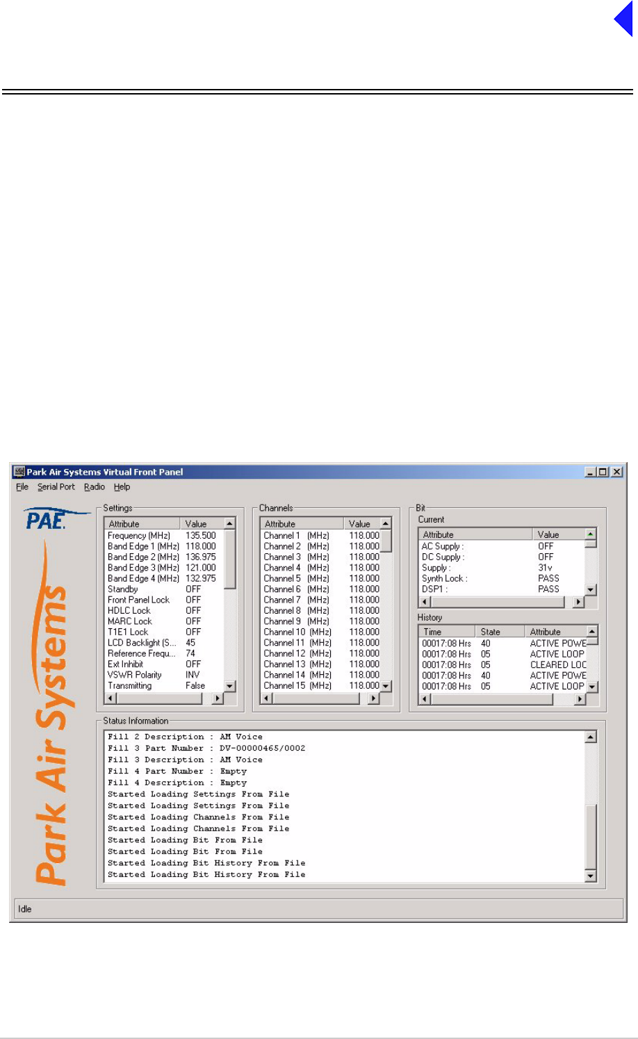
T6T VHF 100 W Transmitter Page 22 Maintenance
Back to Transmitter
Main Page
Virtual Front Panel (VFP)
Virtual Front Panel (VFP) software is supplied on CD-ROM and is compatible with any PC or laptop
running Windows 2000™ or Windows XP™. The VFP allows changes to a radio’s settings and channel
information, it displays the current BIT state, displays BIT history, allows security locks to be set, and
provides maintenance facilities.
A radio can be set up using the front panel Scroll/Select switch and LCD, or by using the VFP. Using the
VFP has several advantages over setting the transmitter from the front panel; these are:
❑A profile of the transmitter’s operation settings and channel information can be created, stored on
disk, and then recalled to download into other transmitters
❑A print out of the transmitter’s profile can be made from the VFP
❑Front Panel Lock is available only when using the VFP. As part of the transmitter’s Settings (see
Fig 2), Front Panel Lock can be set to ON. When selected to on, no settings or frequency
information can be changed from the front panel
❑If the transmitter is part of a MARC system or operates in a digital mode, a MARC Lock, HDLC
Lock and T1E1 Lock are available when using the VFP. When selected to on, no settings or
frequency information can be changed from the MARC equipment screen, or the digital control
equipment.
Fig 2 Typical VFP Screen - AM-Voice Profile Shown

T6T VHF 100 W Transmitter Page 23 Maintenance
Back to Transmitter
Main Page
Installing the VFP Software
The VFP software is supplied by Park Air on CD-ROM. The software can be run from the Main page or
installed on your PC via Explorer.
To install the software onto your PC:
(1) Using explorer, display the contents of the CD-ROM supplied by Park Air. Identify the file named
S0473Vxx.EXE (where xx is the version number).
(2) Using the mouse, right click on the file and then select Copy.
(3) Display the Windows desktop. Right click anywhere on the desktop and select Paste.
(4) Check that the VFP icon is shown on the desktop. Reposition the icon as required. The VFP
application is now installed on the PC’s desktop.
VFP Icon
VFP Features
The VFP screen is divided into four main windows: Settings, Channels, BIT and Status Information. Four
colours are used to display text. The colours have the following meanings:
❑Black indicates a valid parameter that has been accepted by the radio.
❑Red indicates an invalid parameter that has been rejected by the radio, or a BIT failure.
❑Green indicates text that has not yet been downloaded to the radio. Text loaded into the VFP from
a previously stored file, or any text that is manually amended is green until it is downloaded into
the radio; after being downloaded into the radio the text changes to black, or if it is invalid, to red.
❑Blue indicates Help text and is shown in the Status Information window.
The Menu Bar
The menu bar has four categories: File, Serial Port, Radio and Help.
File Has the sub-categories: Open, Save and Print. These sub-categories allow the user to
open previously saved profiles, save a new profile, or print a profile.
A special sub-category: File > Save > Diagnostics should only be used when advised by
Park Air.
Serial Port Has the sub-categories: Com 1 and Com 2. Before the VFP can be used, the appropriate
Com 1 or Com 2 must be selected to correspond with the PC’s Com Port used for the
radio connection.
Radio Has the sub-categories: Retrieve, Send, Calibrate and Test.
This category allows a radio’s profile to be loaded into the VFP, allows a profile to be
downloaded from the VFP to a radio, calibrates a radio and initiates a BIT test.
Help Provides detail about the VFP software.

T6T VHF 100 W Transmitter Page 24 Maintenance
Back to Transmitter
Main Page
Settings Window
This window lists all attributes that can be adjusted by the user. If any individual attribute is clicked on
using the mouse, help information is displayed in the Status Information window showing the range of
adjustment for that attribute. Click on the value and use the keyboard to amend it; press Enter to confirm
the new value noting that the amended text is green until it is downloaded into the radio.
Any invalid parameters are not indicated until the Settings are downloaded to the radio. It is the radio that
rejects invalid parameters, not the VFP.
The transmitter reference frequency setting is displayed in the window. Adjusting the reference
frequency is a maintenance operation that requires external test equipment to be connected. The value
shown in the Settings window should not be changed; instead, adjustment of the reference frequency
should be performed using the radio front panel controls as detailed on page 3.
Channels Window
Up to 100 preset channels can be stored in the radio. These are listed in the Channels window. Any
channel frequency can be amended by clicking on the value to amend it and pressing Enter to confirm
the new value. Note that the amended channel is green until it is downloaded into the radio.
Any invalid frequencies are not indicated until the Channels are downloaded to the radio. It is the radio
that rejects invalid frequencies, not the VFP.
BIT Window
Two lists of information are presented. The current BIT status and the BIT history. The BIT history shows
the last 100 entries.
Status Information Window
The Status Information window gives information regarding the type of radio, the software fills, recent
VFP actions and Help information.
To Change the Transmitter’s Profile or Save a Profile
(1) Using a radio to PC Serial Interconnection Lead, Park Air part number 17E12600001, connect
the radio’s front panel Microphone/Diagnostics connector to the PC’s Com Port 1 or Com Port 2
(note which Com Port is used).
(2) Run up the VFP software and check that a blank VFP screen (see Fig 3) is displayed.

T6T VHF 100 W Transmitter Page 25 Maintenance
Back to Transmitter
Main Page
Fig 3 Blank VFP Screen
(3) At the Menu Bar, click on Serial Port and select either Com 1 or Com 2. The selection must
correspond to the port used to connect to the radio.
(4) Load the required information from the radio, or from a stored file. The required information can
be radio settings, frequency channels, BIT information, or all of these.
To load a previously stored file, select File > Open > All
or, File > Open >Settings
or, File > Open > Channel
or, File > Open > BIT
To load information from the radio, select Radio > Retrieve > All
or, Radio > Retrieve > Settings
or, Radio > Retrieve > Channel
or, Radio > Retrieve > BIT
(5) If required, amend any radio Settings or Channel information.
(6) Download the radio’s profile as shown on the VFP screen to either the radio, or to a file.
To download into the radio, select Radio > Send > All
or, Radio > Send > Settings
or, Radio > Send > Channel
To download to a file, select File > Send > All
or, File > Send > Settings
or, File > Send > Channel
or, File > Send > BIT

T6T VHF 100 W Transmitter Page 26 Maintenance
Back to Transmitter
Main Page
(7) Check that after downloading to a radio, no invalid parameters are returned (such parameters
are displayed as red text). If there are invalid parameters, amend them and then repeat the
download.
(8) When there is no further requirement for using the VFP, exit the VFP software and disconnect
the radio from the PC.
To Initiate a BIT Test
(1) Using a radio to PC Serial Interconnection Lead, Park Air part number 17E12600001, connect
the radio’s front panel Microphone/Diagnostics connector to the PC’s Com Port 1 or Com Port 2
(note which Com Port is used).
(2) Run up the VFP software and check that a blank VFP screen is displayed.
(3) At the Menu Bar, click on Serial Port and select either Com 1 or Com 2. The selection must
correspond to the port used to connect to the radio.
(4) At the Menu Bar select Radio > Test.
(5) An interruptive BIT test now takes place. The results are displayed in the BIT window.
(6) If there is no further requirement for using the VFP, exit the VFP software and disconnect the
radio from the PC.
To Calibrate the Transmitter
(1) Connect a dummy load via a power meter to the transmitter Antenna connector.
(2) Remove the transmitter’s bottom cover.
(3) Using a radio to PC Serial Interconnection Lead, Park Air part number 17E12600001, connect
the radio’s front panel Microphone/Diagnostics connector to the PC’s Com Port 1 or Com Port 2
(note which Com Port is used).
(4) Run up the VFP software and check that a blank VFP screen is displayed.
(5) At the Menu Bar, click on Serial Port and select either Com 1 or Com 2. The selection must
correspond to the port used to connect to the radio.
(6) At the Menu Bar select Radio > Retrieve > All.
(7) At the Menu Bar select Radio > Calibrate. The Confirm screen will then be displayed to remind
you that a dummy load must be connected before proceeding.
During an interruptive BIT test, the transmitter radiates modulated carrier waves at the set power.
Users should therefore obtain the necessary authority before initiating a test.
If the test is to be carried out with the antenna disconnected, ensure a load is fitted to the
transmitter's Antenna connector.
In order to test the line input stages, an internally generated 1 kHz tone is injected into the line input
circuit. Any other audio present on the line input will cause the test to be inaccurate. Therefore the
transmitter MUST NOT be keyed during the test.

T6T VHF 100 W Transmitter Page 27 Maintenance
Back to Transmitter
Main Page
(8) With the Confirm screen displayed and dummy load connected, select Yes to continue with the
calibrate routine. The Progress screen will then be displayed.
(9) When the PA Control/PA loop has been calibrated the Progress screen disappears and the VFP
screen reappears showing a calibration complete message in the Status Information window.
(10) Gain access to the PA Control module and identify RV8 (see Fig 4). From the transmitter front
panel AM-Voice or AM-MSK Settings screen, select PTT On.
(11) From the Settings window of the VFP screen, note the RF power setting. Adjust RV8 until the
power meter reads this value.
(12) From the transmitter front panel AM-Voice or AM-MSK Settings screen select PTT Off, then
remove the power meter and dummy load. This completes the calibration routine.
(13) When there is no further requirement for using the VFP, exit the VFP software and disconnect
the radio from the PC.

T6T VHF 100 W Transmitter Page 28 Maintenance
Back to Transmitter
Main Page
Location of RV8
Fig 4 Location of PA Control Module RV8
R130
R131
R125
C421
R135
RV8
CN4
R455
R456
C424
R348
D24
R231
R382 R243
TP10
Small Screening Can
RV8
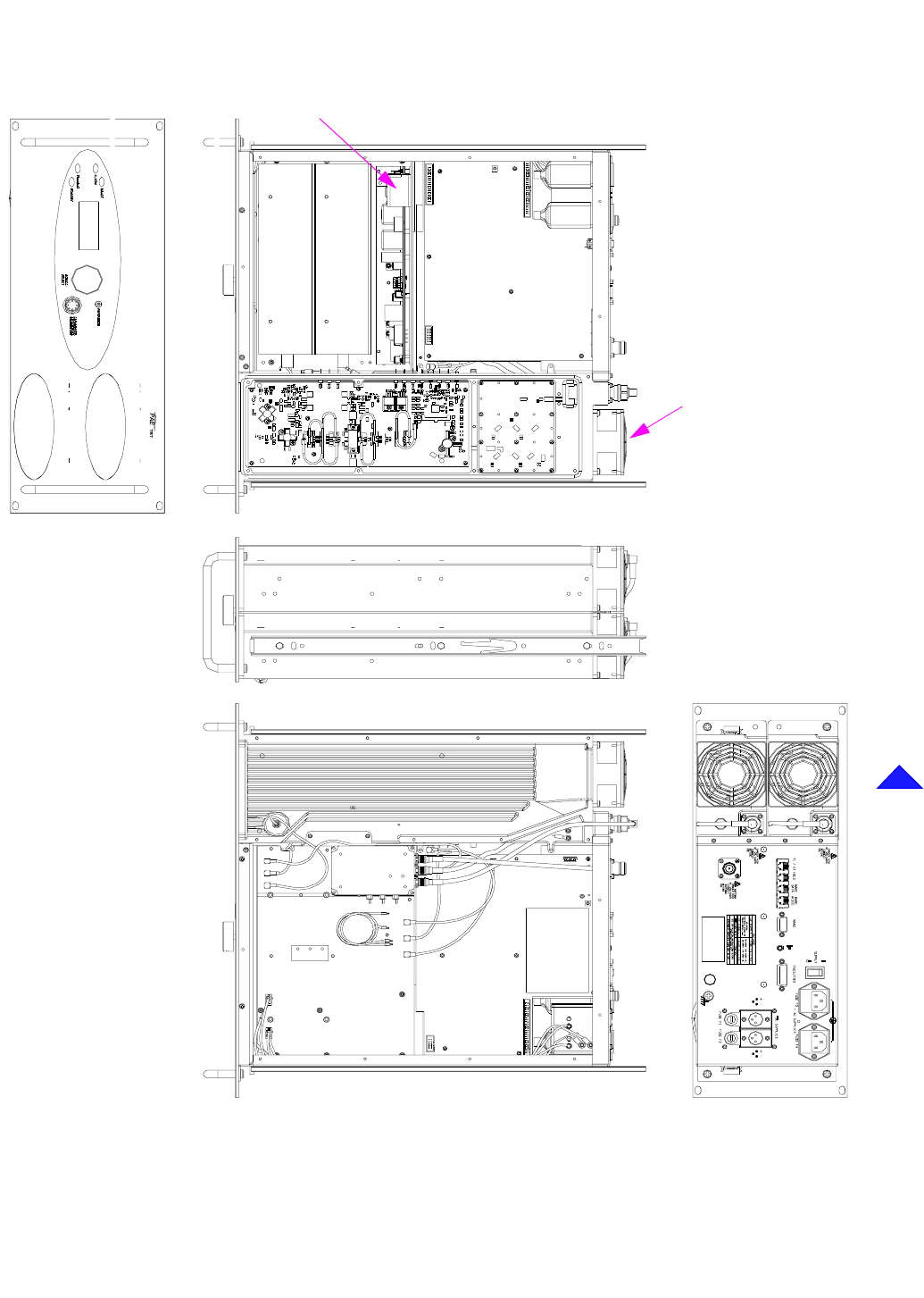
Back to Transmitter Main Page
Fig 5 T6T 100 W Module Location Diagram
Processor Module
PSU-1
PSU-2
PA-2
PA Control
Module
Combiner
BIT Module
BOTTOM
TOP
PSU Regulation
Module
PA-1
SIDE
REAR
FRONT
Cooling Fans
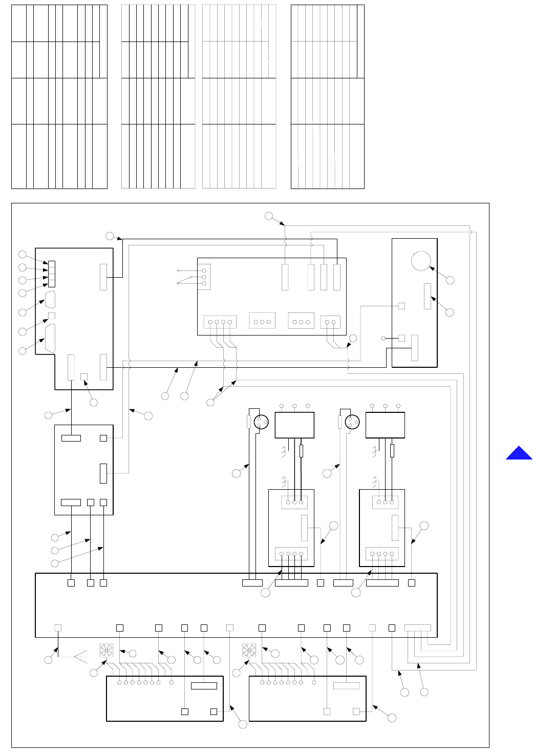
Back to Transmitter Main Page
Fig 6 Wiring and Interconnection Diagram
CN3 CN4
FacilitiesMARC
CN2
CN1
EXT
SPKR
CN2
Microphone/
Diagnostics
FrontPanel
FrontPanelFrontPanel
FrontPanel
CN3 CN1
CN5CN4
CN7 CN5CN6 Processor
ProcessorProcessor
Processor
CN8
T1/E1
MARCAUDIO
MARCDATA
HDLC
ABCD
ReferenceFrequency
(Front Panel)
CN24
(Rear Panel)
CN6
CN5
CN1
PA Control
PA ControlPA Control
PA Control
CN3
CN4
CN2
PSU-2
PSU-2PSU-2
PSU-2
1
CN1
4
3
2
L
N
E
CN4
Ac Input
(Rear Panel)
L
N
E
Mains IEC
Connector
Filtered/
Fused
PSU-1
PSU-1PSU-1
PSU-1
1
CN1
4
3
2
L
N
E
CN4
Ac Input
(Rear Panel)
L
N
E
Mains IEC
Connector
Filtered/
Fused
CN12
CN7
CN15
CN27
CN16
CN4
CN3
CN1
CN10
CN11
CN2
CN4
CN5
Power Supply Regulation
Power Supply RegulationPower Supply Regulation
Power Supply Regulation
CN3
(Rear Panel)
CN7
CN6
Supply shown in
off position
132
CN2 1
2
1
3
2
CN1
4
CN8
1L
2N
3E
CN9
21
Dc Input - 1
Dc Input - 1Dc Input - 1
Dc Input - 1
(Rear Panel)
3
21
Dc Input - 2
Dc Input - 2Dc Input - 2
Dc Input - 2
(Rear Panel)
3
T6 100 W Combiner BIT
T6 100 W Combiner BITT6 100 W Combiner BIT
T6 100 W Combiner BIT
Fan
CN13
CN5
CN26
CN17
CN22
CN10
CN1
CN8
CN2
CN4
CN5
CN7
CN9
CN6
CN12
PA-1
PA-1PA-1
PA-1
CN3
CN14
CN6
CN25
CN18
CN23
Fan
CN10
CN1
CN8
CN3
CN2
CN4
CN5
CN7
CN9
CN6
CN12
PA-2
PA-2PA-2
PA-2
1L
2N
3E
5
7 8
25
24
23
17
17 19
20
20
11
12
13
14
15
11
12
13
14
15
16
31 2
4
9
10
10
6
19
22 21
26
18
A B C D
17
17
(Rear Panel)
PinNumber
Connections A
CN7-6
CN7-7
CN7-8
CN7-2
CN7-4
CN7-3
CN7-5
CN7-1
Pin Number
Connections B
CN7-6
CN7-7
CN7-8
CN7-2
CN7-4
CN7-3
CN7-5
CN7-1
PinNumber
Connections C
6
7
8
2
4
3
5
1
PinNumber
Connections D
6
7
8
2
4
3
5
1
Characteristic
ANSI T1.403-1995 (T1), ITU-
T:G.703(E1)
ANSIT1.403-1995(T1),ITU-
T:G.703(E1)
n/c
n/c
n/c
R TIP
T RING
n/c
T TIP
R RING
Name
Characteristic
0V
21.6V to 32V
RS422
RS422
RS422
RS422
RS422
RS422
Name
Unregulated Supply
Ground
HDLC CLB
HDLC CLA
HDLC RxB
HDLC TxB
HDLC RxA
HDLC TxA
Characteristic
0V
21.6V to 32V
RS422
RS422
RS 422
RS422
n/c
Unregula ted Supply
Data RxB (Data In+)
Data TxB (DataOut+)
Data Rx A (Data In -)
Data TxA (DataOut-)
Ground
Remote Supply On/Off
Name
Characteristic
+20dBm to -20dBm 600R
+20dBm to -20dBm 600R
0V
0V or +10V to +60V or
-10V to -60V at 6mA
+20dBm to -20dBm 600R
+20dBm to -20dBm 600R
NPN Open Collector
Grounding Transistor
0V or +10V to +60V or
-10V to -60V at 6mA
Not used
Fast Antenna
Change Over/PTT
Not used
LineIn+
PTT Input
LineIn-
Not used
Ground
Name
18
Back to Transmitter Main Page
Fig 7 Wiring List
Characteristic
FrontPanel
Connections 21
CN3-1
CN3-2
CN3-3
Groun d
LoudspeakerOutput
Name
n/c n/c
0 V
7.5 V pk-pk Max
Connections 18 Name Characteristic
PSU-1 PSU-2
dc OK
Ground
PSU off
CN4-2
CN4-1
CN4-3
0 V = off
TTL, high = PSU on
0 V
Connections 17 Name Characteristic
CN7-6
CN7-7
CN7-8
CN7-2
CN7-4
CN7-3
CN7-5
CN7-1
Regulation
Pin Diode - ve
V Unregulated
n/c
AC Derived Supply
DC Derived Supply
Ground
Ground
Ground 0v
29v
21.6v to 32v
0v
-30v to -35v
CN3-2
CN3-1
n/c
CN1-3 & 4
CN2-2
CN2-1
CN3-3
CN1-1 & 2
21.6v to 32v
0v
n/c
Microphone/
Diagnostics
FrontPanel
CN2-1 1 Ground - Microphone 0 V
CN2-6
2 Transmit Data RS232
CN2-3 3 MIC PTT
CN2-4 4 Receive Data RS232
CN2-5 5 Sidetone (HeadsetDrive) 3 Vac pk-pk, 200R
CN2-2
6Microphone Input
CN2-7 7 Ground 0 V
0V=PTT, 5V pull-up = not PTT
6k8 input impedance, 5mV sensitivity
Connections 22 Name Characteristic
Connections 19 Name Characteristic
CN1-1
CN1-6
CN1-5
CN1-2
Ground Supply
V Unreg
Ground Supply
V Unreg
0 V
0 V
29 V
29 V
0V
0V=on
o/c okPSU ok
0V
PSU off
Regulation
0V
PSU ok
0V
0V ok
PSU off 0V=off
Name Characteristic
Connections 16
CN6-3
CN6-5
CN6-4
CN6-6
CN6-2
CN6-1
CN12-3
CN12-1
1 dBm carrierRF Drive
CN10
CN17- 1 CN18-1
Connections 14 Name Characteristic
RF Out put
CN1-1 5 t o 50 WCN22-1 CN23-1
Connections 15 Name Characteristic
Input-1 CN2-2 CN4-2 Fused 21.6 to 32V
Dc Input
Input-2 CN2-1 CN4-1 Ground Supply 0 V
DC Input - 1 DC Input - 2
Input-3 n/c n/c
Name Characteristic
Connections 20
Front PanelProcessor
Connections 24 Name Characteristic
CN4-1
CN4-2
CN4-3
CN4-4
CN1-1
CN1-2
CN1-3
CN1-4
LED Alarm
LED Ready
LED Standby
LED Tx
LCD RS
Open collector (20 mA)
CN4-5
CN4-6
CN4-7
CN4-8
CN4-9
CN4-10
CN4-11
CN4-12
CN4-13
CN4-14
CN4-16
CN4-17
CN4-18
CN1-20
CN1-19
CN4-15
CN1-25
CN4-24
CN4-23
CN1-22
CN1-21
CN1-5
CN1-24
CN1-23
CN1-16
CN4-19
CN4-22
CN4-21
CN4-20
CN1-18
CN1-17
CN1-6
CN1-7
CN4-25
LCD R/W
LCD Backlight
Transmit Data
+5 V Supply
-5 V Supply
Ground
+15V Supply
Ground
Mic PTT
LED RX (not used)
5 V pull-up
TTL
0 V
-5 V
+15V
LCD Enable
Data 3
Data 2
Data 7
Data 6
Data 5
Data 4
RS232
+5 V
0 V
Receive Data
0 V=PTT, 5V pull-up = PTT
Turn+
RS232
Turn-
Sidetone (HeadsetDrive) 3 Vac pk-pk
Loudspeaker Amp Drive
Ground
Mic Input
Ground 0 V
1.6V p-p maximum
0 V
2 V p-p maximum
Push
Ground 0 V
CN1-26
CN4-26
CN1-27
CN4-27
CN1-31
CN1-29
CN4-28
CN1-30
CN4-31
CN4-29
CN1-28
CN4-30
CN4-33
CN1-34
CN1-33
CN4-34
CN1-32CN4-32
Open collector (200 mA)
Data 1
Data 0
CN1-12
CN1-13
CN1-14
CN1-15
CN1-8
CN1-9
CN1-10
CN1-11
5 V pull-up
5 V pull-up
TTL
TTL
TTL
TTL
TTL
TTL
TTL
TTL
TTL
TTL
CN6-7
CN6-6
CN6-10
CN6-9
CN6-8
CN5-10
CN5-9
CN5-6
CN5-7
CN5-8
-15 V Supply
AC Detect
DC Detect
-15 V Supply
Ground
-15 V
-15 V
0 V
CN6-5
CN6-4
CN6-3
CN6-2
CN6-1
CN5-2
CN5-4
CN5-3
CN5-5
CN5-1
+5 V Supply
+15 V Supply
+5 V Supply
+15 V Supply
Ground
+15 V
+5 V
+5 V
0 V
+15 V
n/c
n/c
PAControlRegulation
Connections 25 Name Characteristic
Reference Frequency
Front Panel
-20 dBm to 0 dBmCN5-1 CN4- 1
PA Control
Connections 23 Name Characteristic
CN3-14
CN3-13
CN3-12
CN3-11
CN3-10
n/c
Remote on/off
V Unreg
DC Detect
CN3-9
CN3-8
CN3-7
CN3-6
CN3-5
CN3-4
CN3-3
CN3-2
CN3-1
AC Detect
-15 V Supply
Ground
+5 V Supply
+15 V Supply
+15 V Supply
-15 V Supply
+5 V Supply
Ground
-15 V
21.6 to 32 V
21.6 to 32 V
Open collector
15 V on, 0 V off
+15 V
+5 V
+15 V
-15 V
+5 V
0 V
0 V
0 V=off, open collector = on
n/c
ProcessorRegulation
Connections 26 Name Characteristic
CN4-1
CN4-2
CN4-3
CN4-4
CN4-5
CN4-6
CN4-7
CN4-8
CN4-9
CN4-10
CN4-11
CN4-12
CN4-13
CN4-14
V Unreg
CN6-7 7
CN6-8
CN6-9 9
8
Processor
CN6-1
CN6-2
CN6-3
CN6-5
CN6-6
CN6-4 4
6
5
3
1
2
MARC Port
Data RXA Data In- RS422
RS422
RS422Data TXB Data Out+
Data TXA Data Out-
RS422
Fused 500mA, 21.6 to 32V
+20dBm to -20dBm 600R
PTT Input
Data RXB Data In+
Unregulated Supply
Line In+
Ground 0 V
+20dBm to -20dBm 600RLine In-
Name Characteristic
Connections 1
0V or +10V to +60V or
-10V to -60V at 6mA
CN8 Ring
CN8 Tip External Speaker Drive
External Speaker Drive 3Vac pk-pk max
1
2
CN8 Sleeve Ground 0V3
3Vac pk-pk max
External SpeakerProcessor
Connections 2Name Characteristic
TTL pull-up active low
Grounding output +/-60V,100mA max
TTL pull-up active low
0V
0V
Fused 300mA 21.6 to 32V
Open collector, 0V=Ready
-10dBm, 100R
TTL pull-up active low
n/c
TTL pull-up active low
TTL pull-up activel ow
Potential range 0V to 10V
FacilitiesProcessor
Grounding output +/-60V,100mA max
Grounding output+/-60V,100mAmax
Connections 3Name Characteristic
Squelch Defeat (not used)
Antenna change-over
External VSWR
E-Bit
PTT
Groun d
Groun d
Unregulated Supply
Reserved
Tape Output
BIT Interruptive Test
RSSI (notused)
Ready Output
Inhibit
Antenna change-over
7
5
6
4
2
3
1
9
8
14
15
13
12
11
10
CN5-4
CN5-6
CN5-7
CN5-5
CN5-3
CN5-2
CN5-1
CN5-8
CN5-9
CN5-14
CN5-15
CN5-13
CN5-12
CN5-11
CN5-10
Characteristic
Processor
Connections 4
CN2-1 IF
Name
n/c
Forward Power Sense CN27-1 17 dBm
CN4-1
T6 100 W Combiner BIT PA Control
Connections 7Name Characteristic
PA Control
1 dBm carrierRF Dri ve
CN3-1
CN16- 1
Connections 8Name Characteristic
RF Output
PA
CN4-1 10 to 100 WAntenna Port
Connections 9Name Characteristic
PA Bias EnableCN13-3 CN14-3
CN13-5 CN14-5
CN13-4 CN14-4
Reflected Power
Fan Enable
PA - 1 PA - 2
CN13-6 CN14-6
CN13-2 CN14-2
CN13-1 CN14-1 PA Temperature
Drive Detect
CN4
CN9
CN5
CN7
CN2
CN12 PA Count
T6 100W Combiner BIT
Connections 11 Name Characteristic
50W = 670mV
TTL -High for fan on
TTL -High for bias on
10mV / °C +0.5V
0.5V for +10dBm
TTL, PW = 10ms/50W PA
T6 100W Combiner BIT
CN3-1CN5-1 CN6-1 V Unreg 21.6 to 32V
Connections 12 Name Characteristic
CN3-2CN5-2 CN6-2
PA - 1 PA - 2
-33V -30V to -35V
0 to 4V/0 to 6VFrequency Trim
TTL
TTL
TTL
TTL
TTL -Low OCXO fitted
TTL -High fan on
TTL
BIT Control3 (Not used)
BIT Control2 (Not used)
Step Size (Not used)
V/U Detect
TR Detect
Reserved
OCXO Fitted
Fan Enable
TTL, Pulse width = 10ms/50W PA
TTL
TTL
TTL
TTL
TTL
0to2.5V
10mV/°C
10mV/°C
0 to 5V (5V3dB backoff)
TTL
TTL
TTL
TTL
TTL
BIT Loop Correct
BIT Synth Lock
BIT Open Loop
BIT VSWR OK
BIT Control 1
BITControl0
Reflected Power
PA Temperature
Auto Level Control
External VSWR
PAC Temperature
Narrow/Wide (Not used)
Tx Key
TTL
TTL
TTL
TTL
0V
TTL
0V
TTL pull-up active low
TTL
TTL
TTL
TTL
Filter 3
Data
Phase Load
Clock
Synth Load
Ground
Filter 4
Filter 0
Filter 2
Filter 1
Ground
Power Down
Tx/Rx Detect
PA ControlProcessor
0 to 2.5V
0V
±2.5V
±2.5V
0 to 2.5V
0 to 2.5V
0 to 2.5V
0V
0V
0V
0V
0V
0V
Ground
Ground
Q
Ground
Ground
BIT Q Monitor
BIT I Monitor
RF AGC (Not used)
I
Ground
IF AGC (Not used)
Ground
Ground
PA Count
RFPA Bias Disable
TTL
TTL
Connections 5Name Characteristic
CN1-7
CN1-9
CN1-8
CN1-2
CN1-3
CN1-1
CN1-5
CN1-6
CN1-4
CN1-14
CN1-50
CN1-45
CN1-43
CN1-44
CN1-47
CN1-46
CN1-49
CN1-48
CN1-28
CN1-42
CN1-41
CN1-38
CN1-39
CN1-36
CN1-37
CN1-40
CN1-32
CN1-31
CN1-29
CN1-30
CN1-34
CN1-33
CN1-35
CN1-21
CN1-24
CN1-23
CN1-22
CN1-26
CN1-27
CN1-25
CN1-17
CN1-16
CN1-15
CN1-20
CN1-19
CN1-18
CN1-10
CN1-12
CN1-13
CN1-11
CN1-14
CN1-50
CN1-48
CN1-49
CN1-47
CN1-45
CN1-46
CN1-44
CN1-43
CN1-42
CN1-41
CN1-15
CN1-16
CN1-21
CN1-22
CN1-23
CN1-17
CN1-19
CN1-18
CN1-20
CN1-24
CN1-25
CN1-30
CN1-26
CN1-29
CN1-28
CN1-27
CN1-31
CN1-32
CN1-33
CN1-34
CN1-36
CN1-35
CN1-37
CN1-40
CN1-39
CN1-38
CN1-10
CN1-13
CN1-12
CN1-11
CN1-7
CN1-9
CN1-8
CN1-6
CN1-5
CN1-4
CN1-2
CN1-3
CN1-1 Forward Power Sense 17 dBm
Connections 13 Name Characteristic
CN25-1 CN26-1
T6 100 W Combiner BIT
CN8
PA - 1 PA - 2
CN10-2 CN11-2
CN10-1 CN11-1
CN10-3 CN11-3
CN1-3 CN3-3
CN1-2 CN3-2
CN1-1 CN3-1
CN1-4 CN3-4
PA Heatsink
CN6 Fan Control
Ground 0 V
10 V approx or 26.5VFan
Fan
RFPA 2 RFPA 2
Connections 10 Name Characteristic
CN3-3CN5-3 C N6-3 Ground Supply 0V
CN12-3
CN12-6
CN12-4
CN12-5
Open collector (20 mA)
Open collector (20 mA)
Open collector (20 mA)
Open collector (20 mA)
T6 100 W Combiner BIT
PA - 1 PA - 2T6 100 W Combiner BIT
T6 100 W Combiner BIT PA - 1 PA - 2
T6 100 W Combiner BIT
T6 100W Combiner BIT
PSU-1 PSU-2
T6 100W Combiner BIT
T6 100W Combiner BIT
T6 100W Combiner BIT
PA Bias Enable
Reflected Power
Fan Enable
PA Temperature
Drive Detect
PA Count
Connections 6Name Characteris tic
50 W = 670mV
TTL High for fan on
TTL High for bias on
10mV / °C +0.5V
0.5V for +10dBm
TTL, Pulse width = 10ms/50 W PA
T6 100W Combiner BIT
CN15-1
CN15-5
CN15-4
CN15-3
CN15-2
CN15-6
CN2-3
CN2-5
CN2-4
CN2-6
CN2-2
CN2-1
PA Control
Not UsedCN15-7
CN15-8
CN15-9
CN15-10
Not Used
Not Used
Not Used
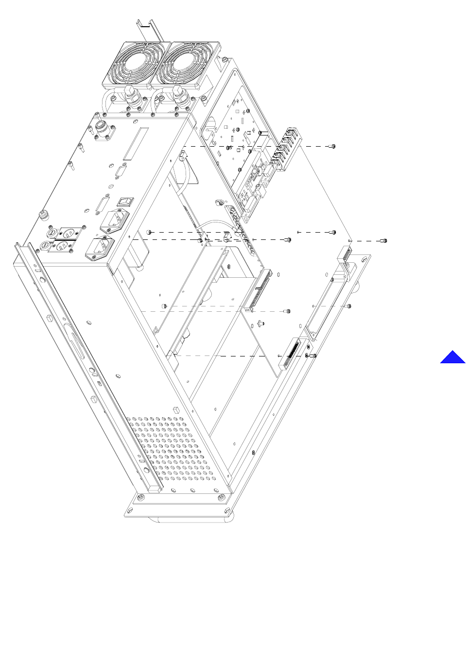
Back to Transmitter Main Page
Fig 8 Processor Module - Removal and Refitting Detail
CN6
CN5
CN4
CN3
CN1
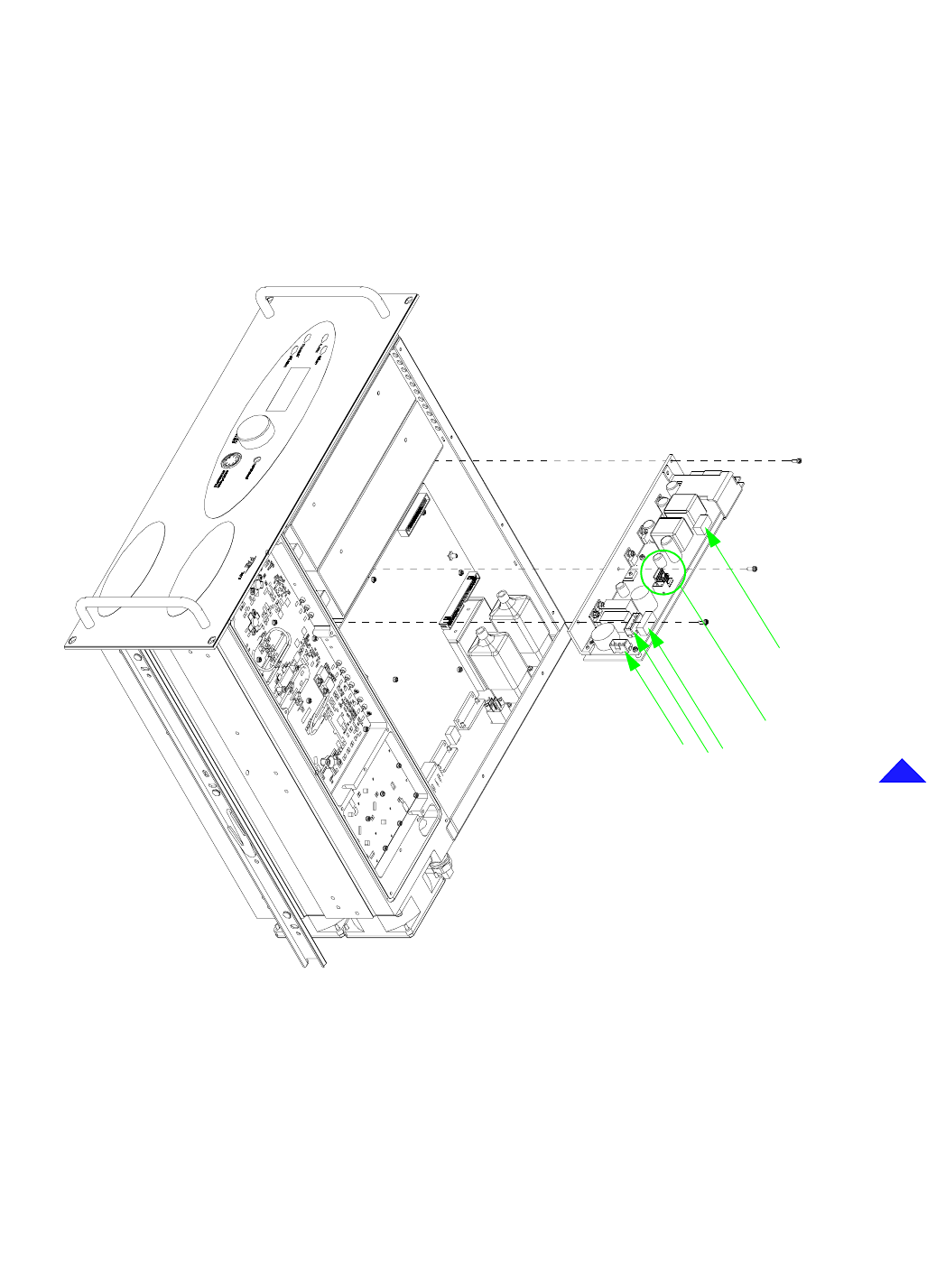
Back to Transmitter Main Page
Fig 9 PSU Regulation Module - Removal and Refitting Detail
CN3
CN1
CN4
CN5 CN2, CN6, CN7
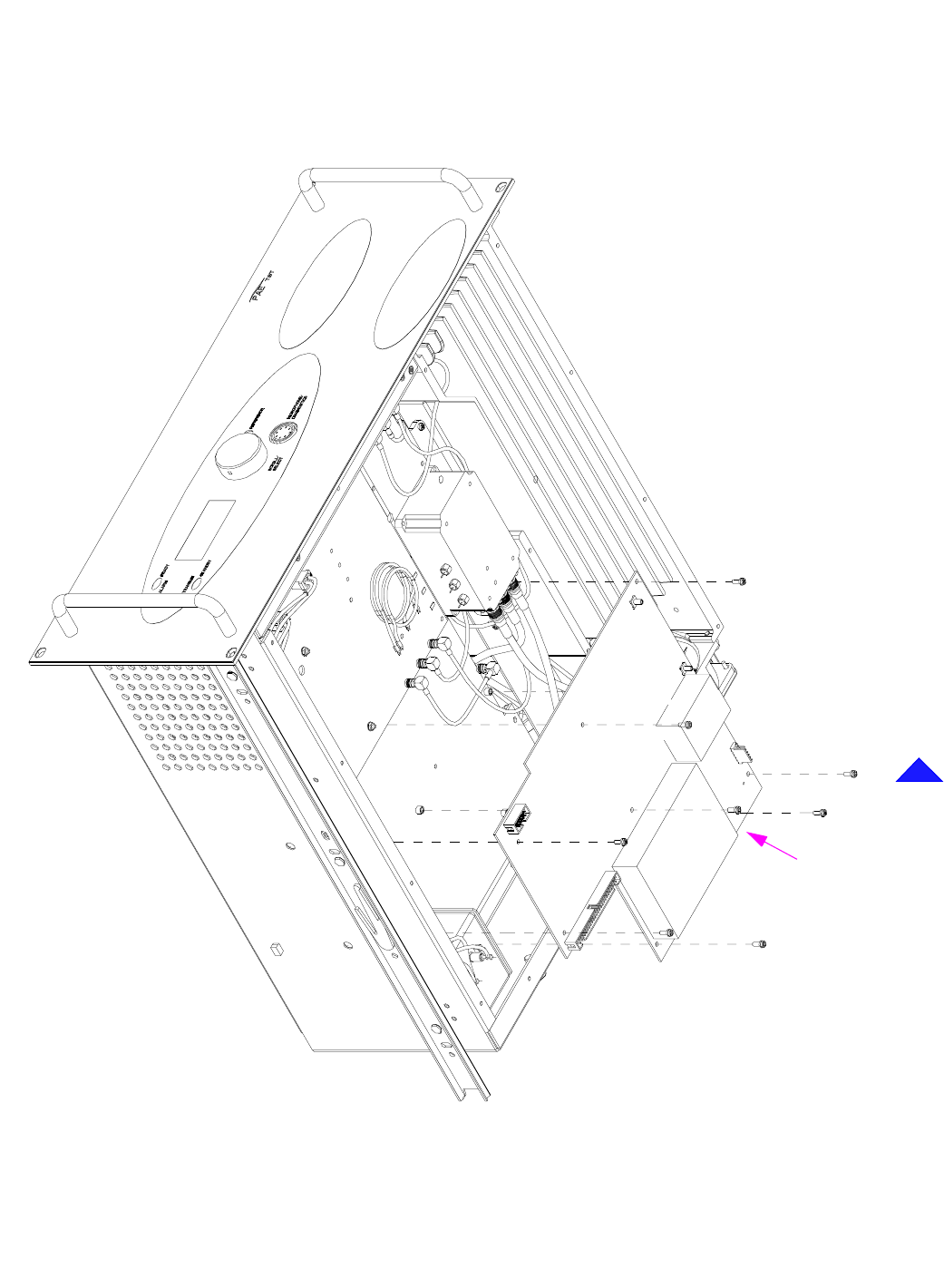
Back to Transmitter Main Page
Fig 10 PA Control Module - Removal and Refitting Detail
CN4
CN3
CN6
CN1
CN2
CN5 (behind box)
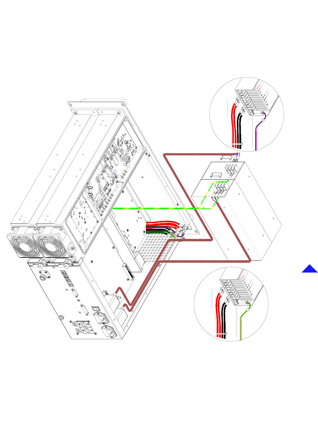
Back to Transmitter Main Page
Fig 11 Power Supply - Removal and Refitting Detail
PSU to Bit Combiner (dc Connections)
Bit Combiner to PSU (fan control)
PSU to Bit Combiner (dc Connections)
Bit Combiner to PSU (fan control)
PSU 2
PSU 1
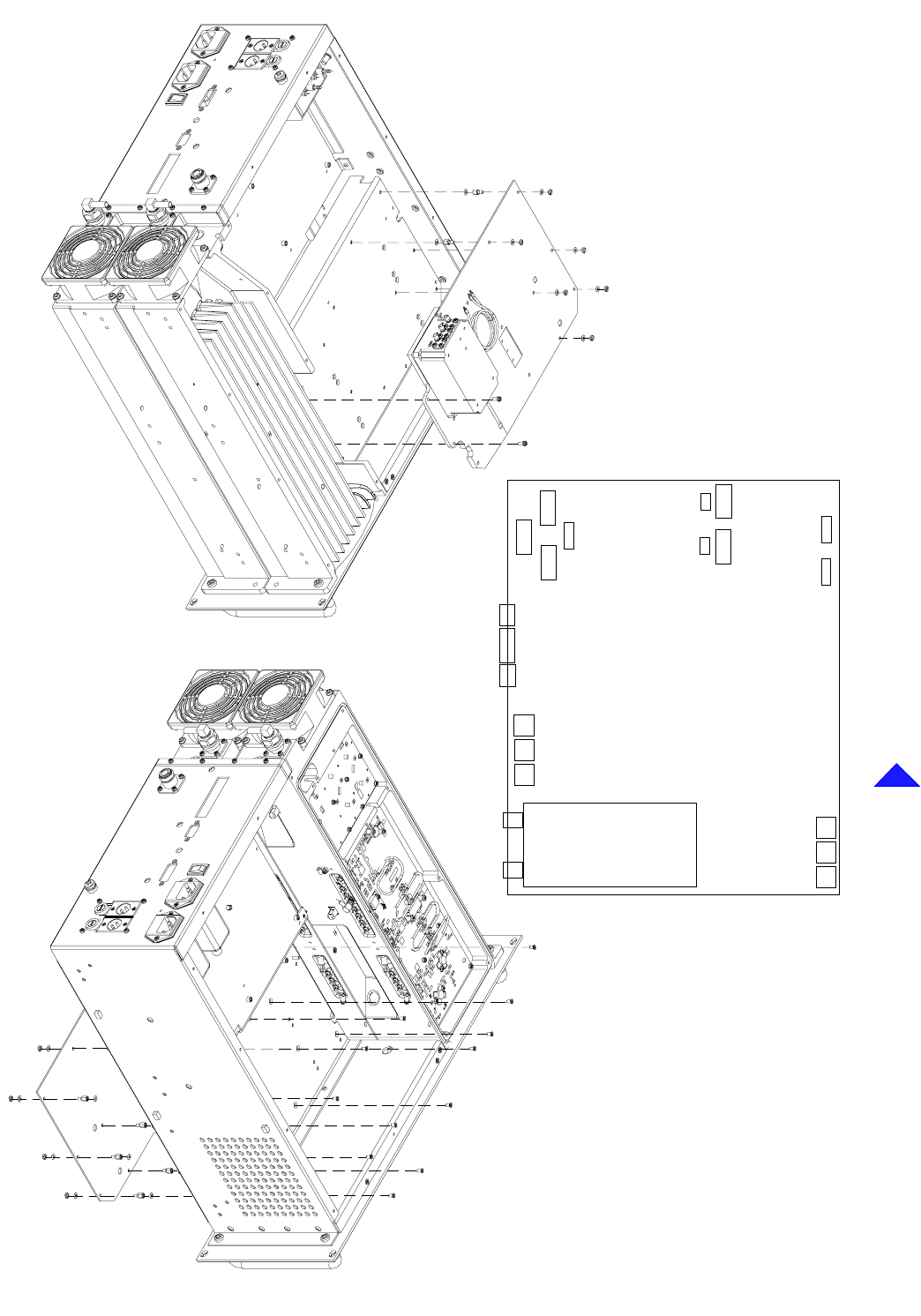
Back to Transmitter Main Page
Fig 12 Combiner BIT Module - Removal and Refitting Detail
CN5 CN6
CN7
CN12
CN15
CN14 CN13
CN26
CN25CN27
CN1
CN3
CN2 CN4
CN22
CN23
CN24
CN18
CN17 CN16
Locations
CN11 CN10
Connector
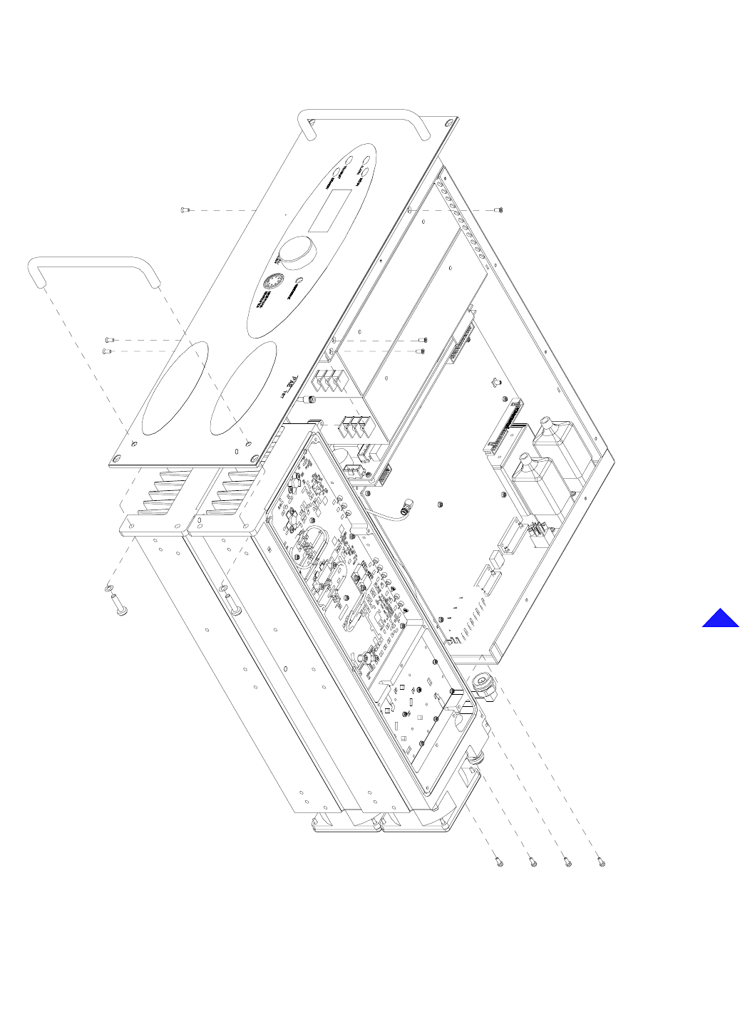
Back to Transmitter Main Page
Fig 13 PA Modules - Removal and Refitting Detail
PA 1
PA 2
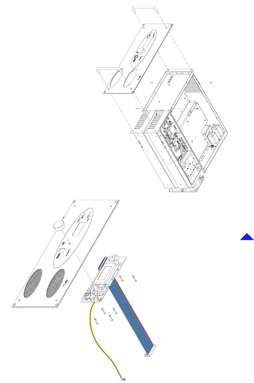
Back to Transmitter Main Page
Fig 14 Front Panel and Front Panel Assembly PCB Removal and Refitting Detail
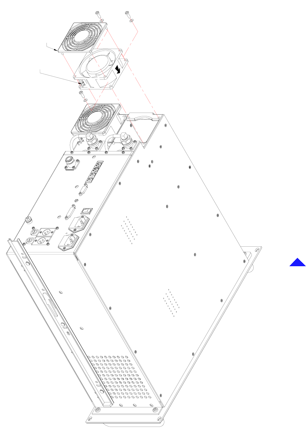
Back to Transmitter Main Page
Fig 15 Cooling Fans - Removal and Refitting Detail
power connections here
Finger guard
AIRFLOW

Back to Transmitter Main Page
Intentionally Blank