Panasonic of North America 96NKX-TDA1052 2.4GHz CELL STATION User Manual 100 TDE IM 07 02
Panasonic Corporation of North America 2.4GHz CELL STATION 100 TDE IM 07 02
UserManual.wiki
>
Panasonic of North America
>
96NKX-TDA1052 User Manual
>
users manual
Contents
1.
statement of security code
2.
users manual
users manual
Navigation menu
Upload a User Manual
Namespaces
Wiki Guide
HTML
PDF
Info
Views
User Manual
Discussion / Help
Navigation


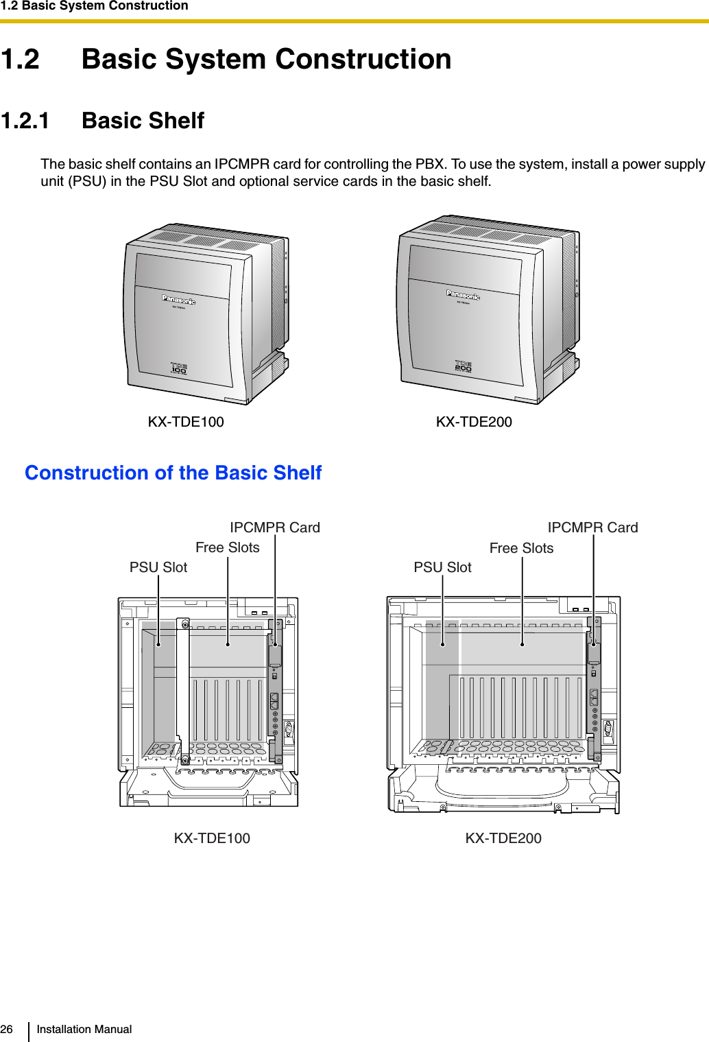
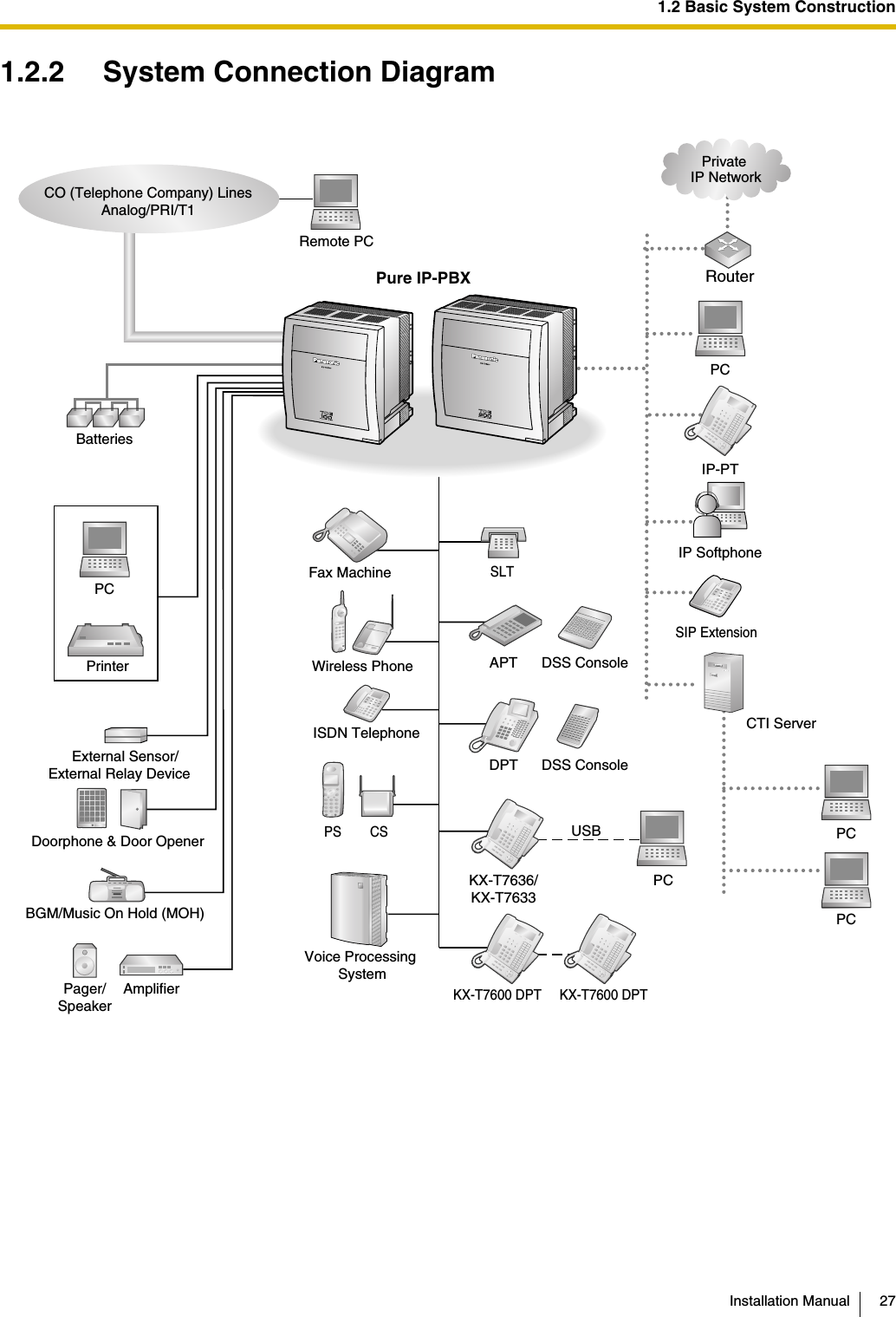
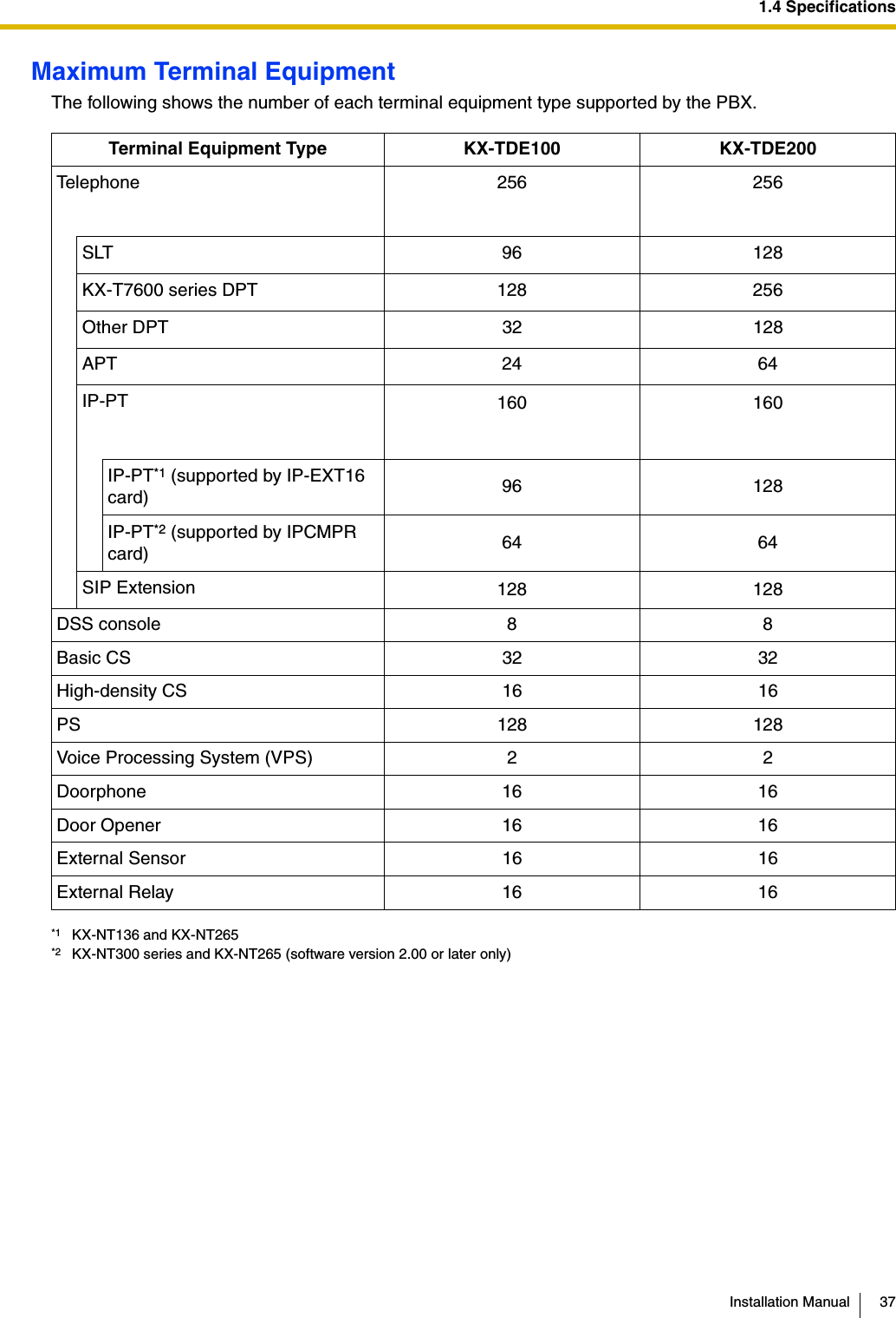
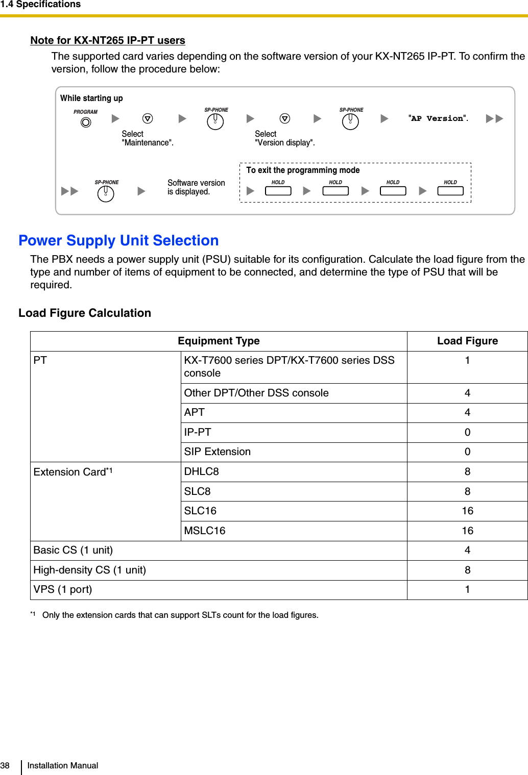
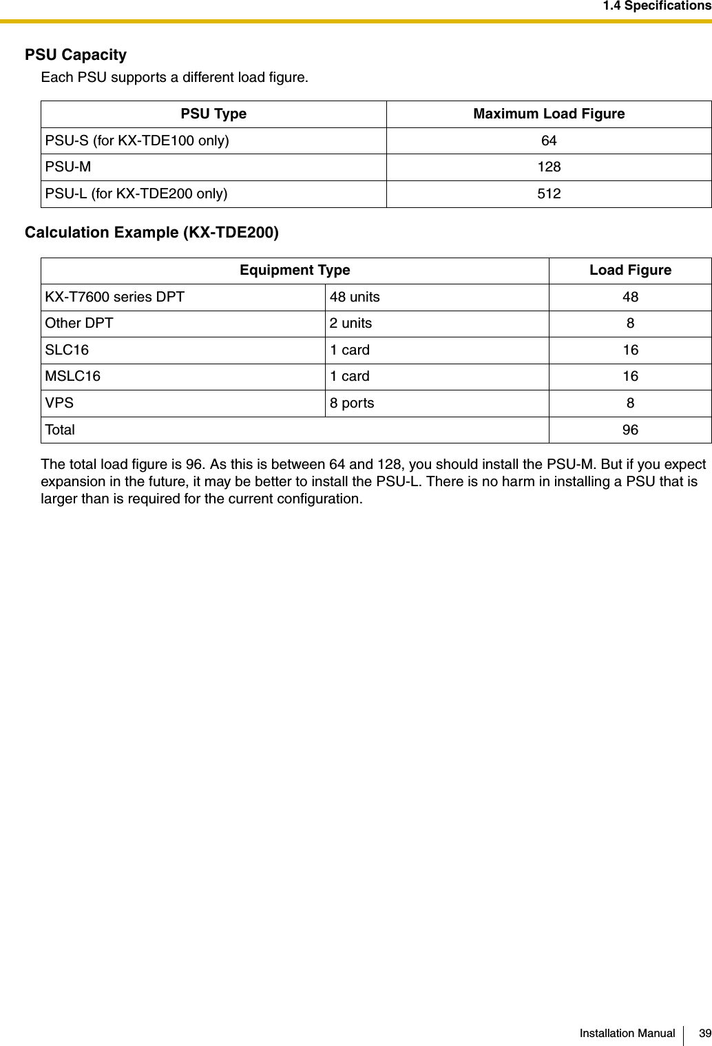
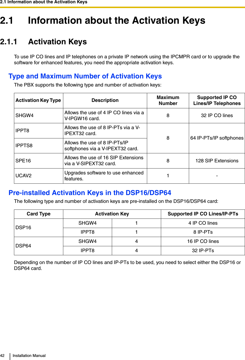
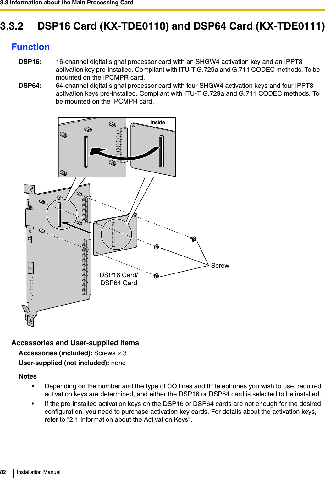
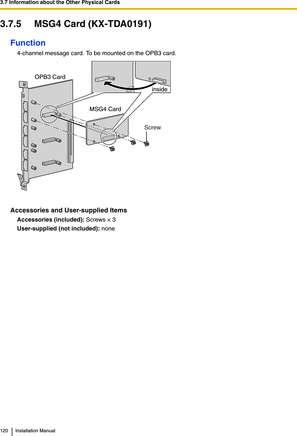
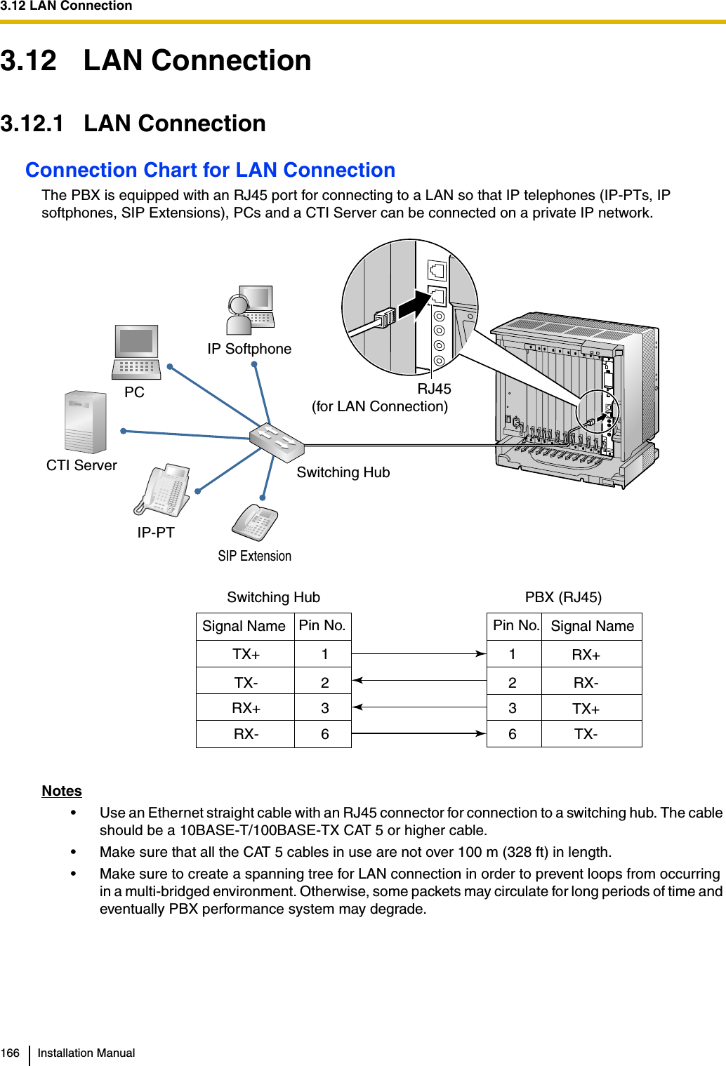
![12 Installation ManualIntroductionThis Installation Manual is designed to serve as an overall technical reference for the Panasonic Pure IP-PBX, KX-TDE100/KX-TDE200. It provides instructions for installing the hardware, and programming the PBX using the KX-TDE Maintenance Console.The Structure of this ManualThis manual contains the following sections:Section 1 System OutlineProvides general information on the PBX, including the system capacity and specifications.Section 2 Activation Key InstallationDescribes information on activation keys, including how to obtain an activation key and install it in the SD Memory Card.Section 3 InstallationDescribes the procedures to install the PBX. Detailed instructions for planning the installation site, installing the shelves and optional service cards, and cabling of peripheral equipment are provided. Further information on system expansion and peripheral equipment installation is included.Section 4 Guide for the KX-TDE Maintenance ConsoleExplains the installation procedure, structure, and basic information of the KX-TDE Maintenance Console.Section 5 TroubleshootingProvides information on the PBX and telephone troubleshooting.About the Other ManualsAlong with this Installation Manual, the following manuals are available:Feature ManualDescribes all basic, optional and programmable features of the PBX.PC Programming ManualProvides step-by-step instructions for performing system programming using a PC.PT Programming ManualProvides step-by-step instructions for performing system programming using a PT.Operating ManualProvides operating instructions for end users using a PT, SLT, PS, or DSS Console.About the software version of your PBXThe contents of this manual apply to PBXs with a certain software version, as indicated on the cover of this manual. To confirm the software version of your PBX, see "How do I confirm the software version of the PBX or installed cards?" in the FAQ of the PC Programming Manual, or "[190] Main Processing (MPR) Software Version Reference" in the PT Programming Manual.Trademarks• The Bluetooth word mark and logos are owned by the Bluetooth SIG, Inc. and any use of such marks by Matsushita Electric Industrial Co., Ltd. is under licence.• Microsoft and Windows are either registered trademarks or trademarks of Microsoft Corporation in the United States and/or other countries.• Intel and Celeron are trademarks or registered trademarks of Intel Corporation or its subsidiaries in the United States and other countries.](https://usermanual.wiki/Panasonic-of-North-America/96NKX-TDA1052.users-manual/User-Guide-799956-Page-12.png)

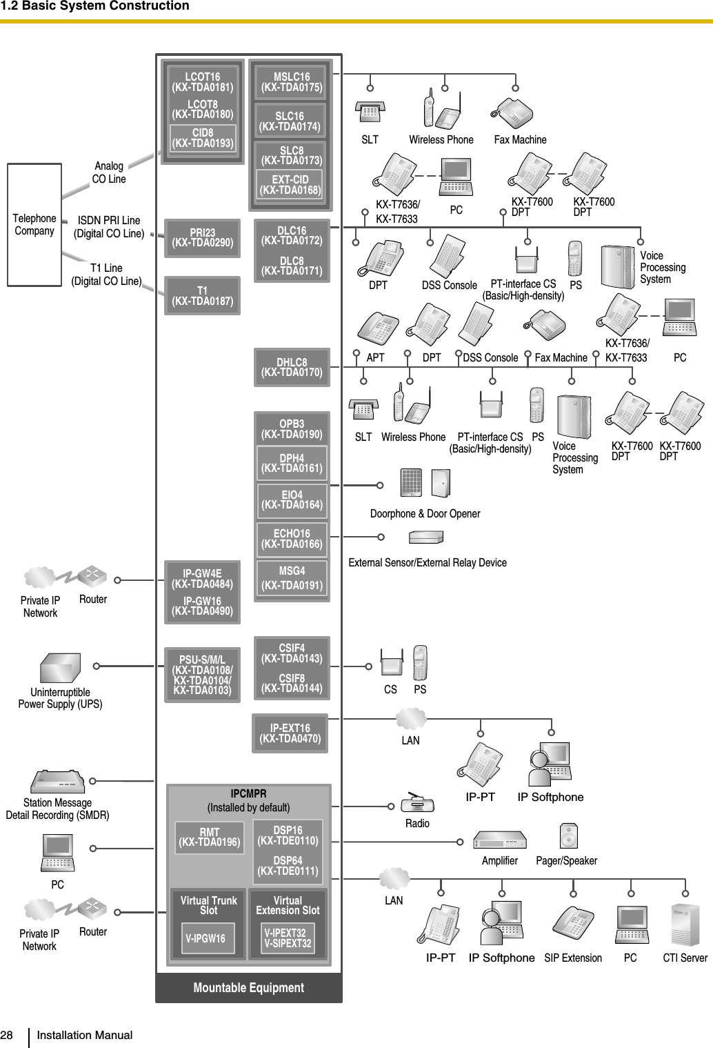
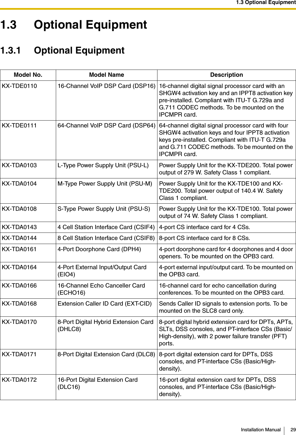
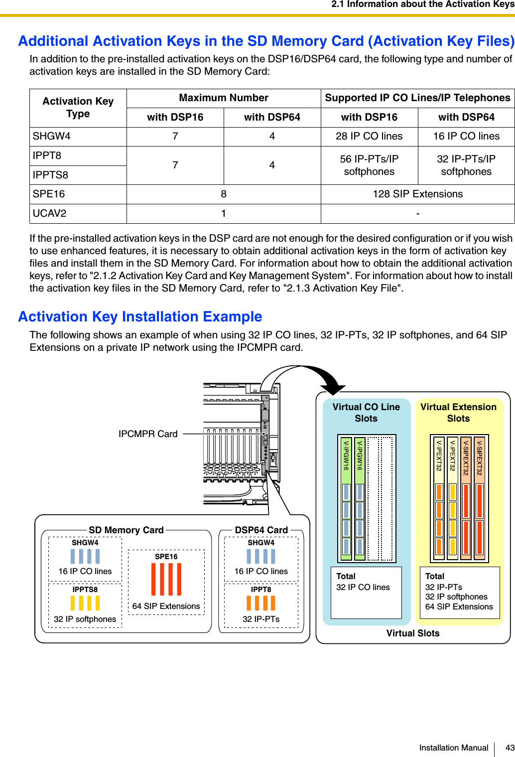
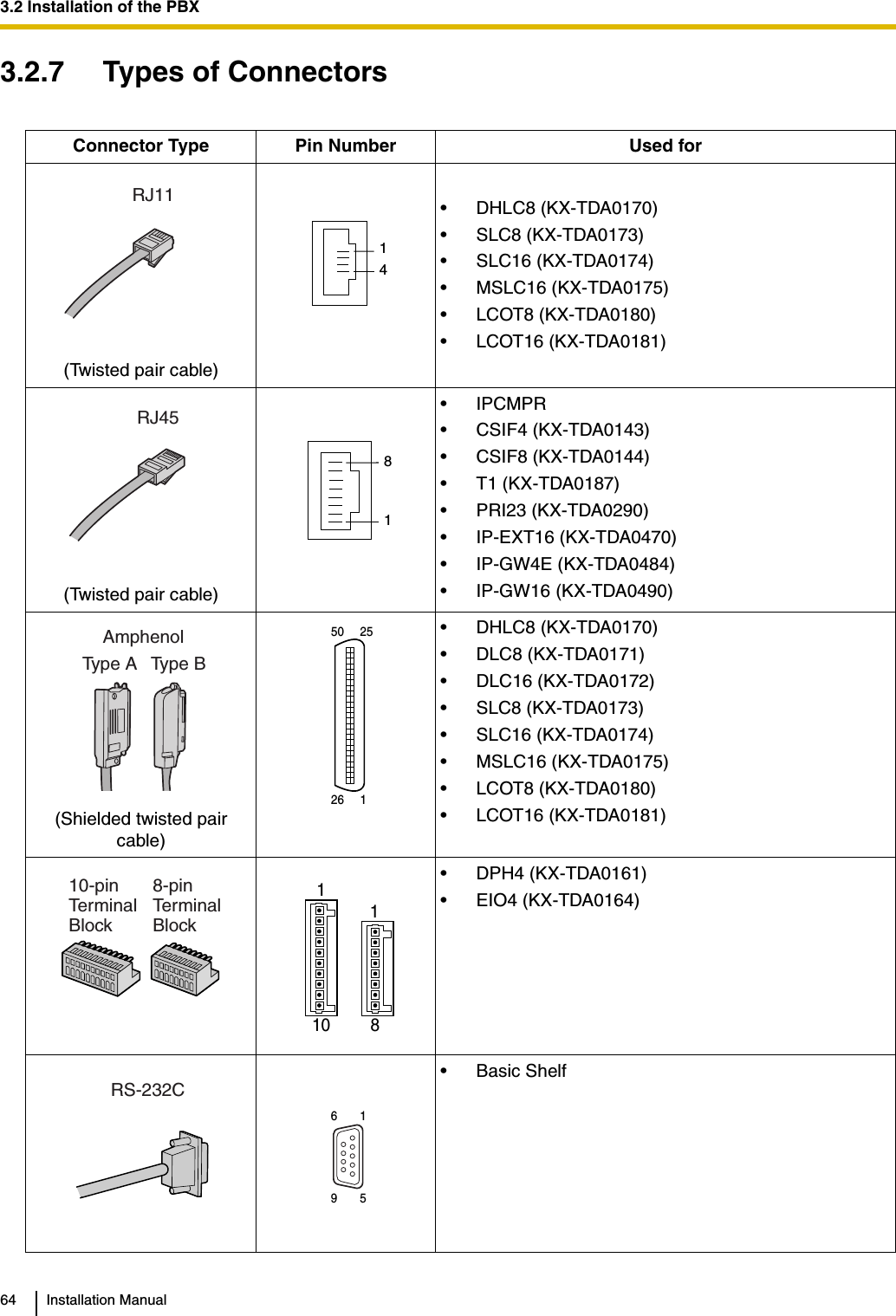
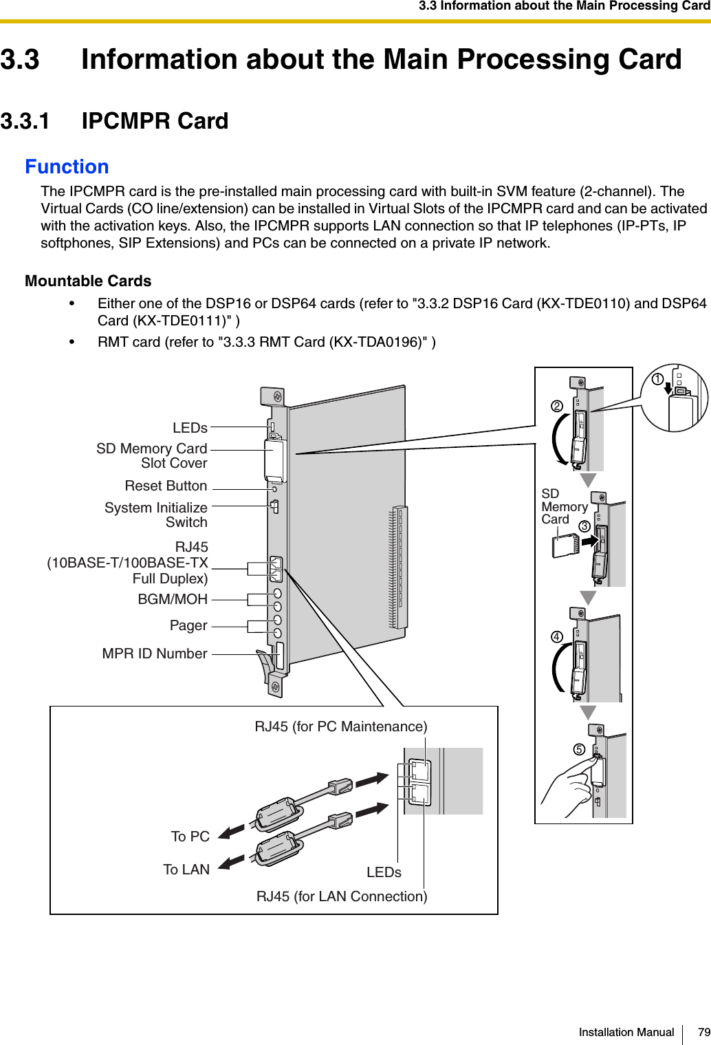
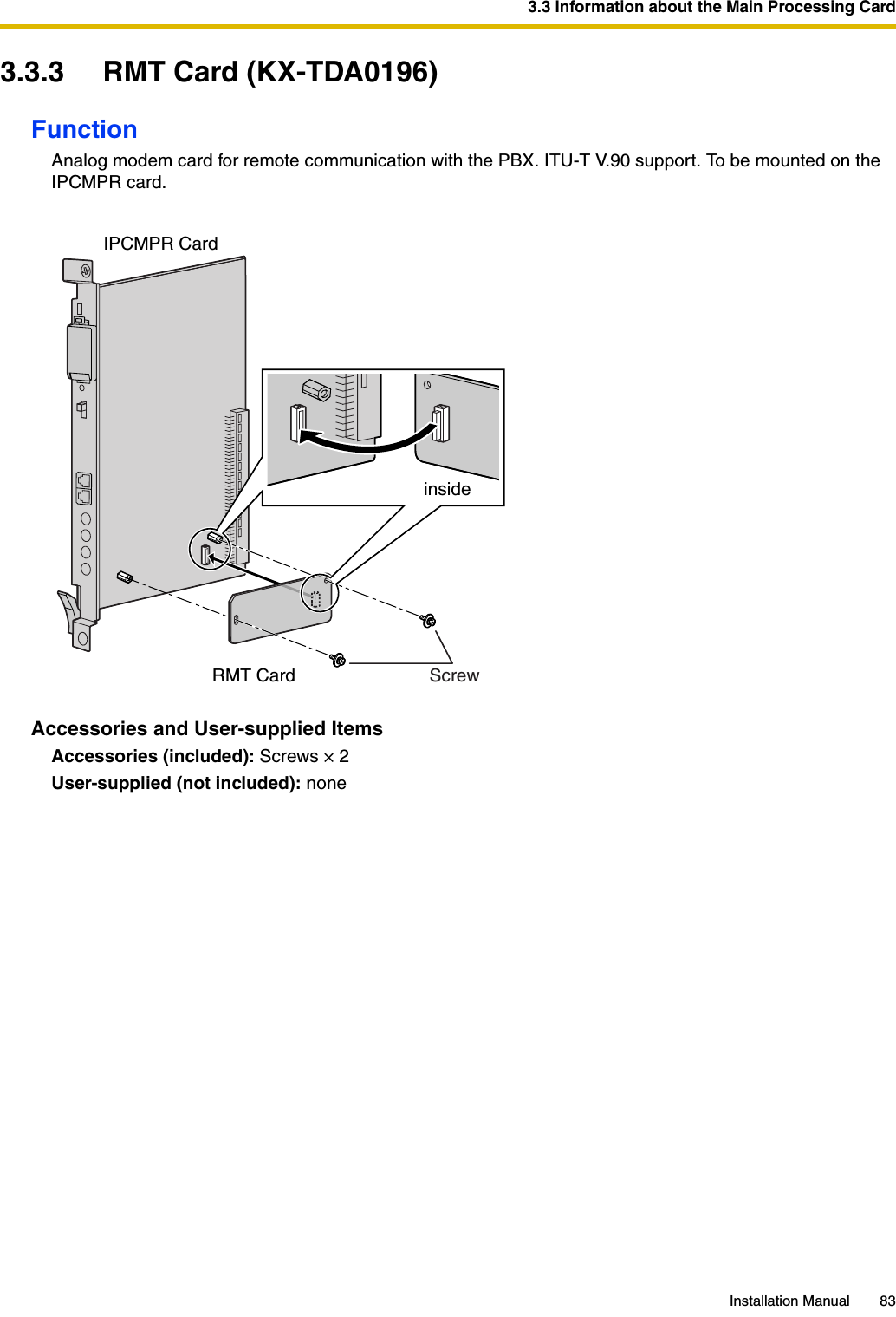
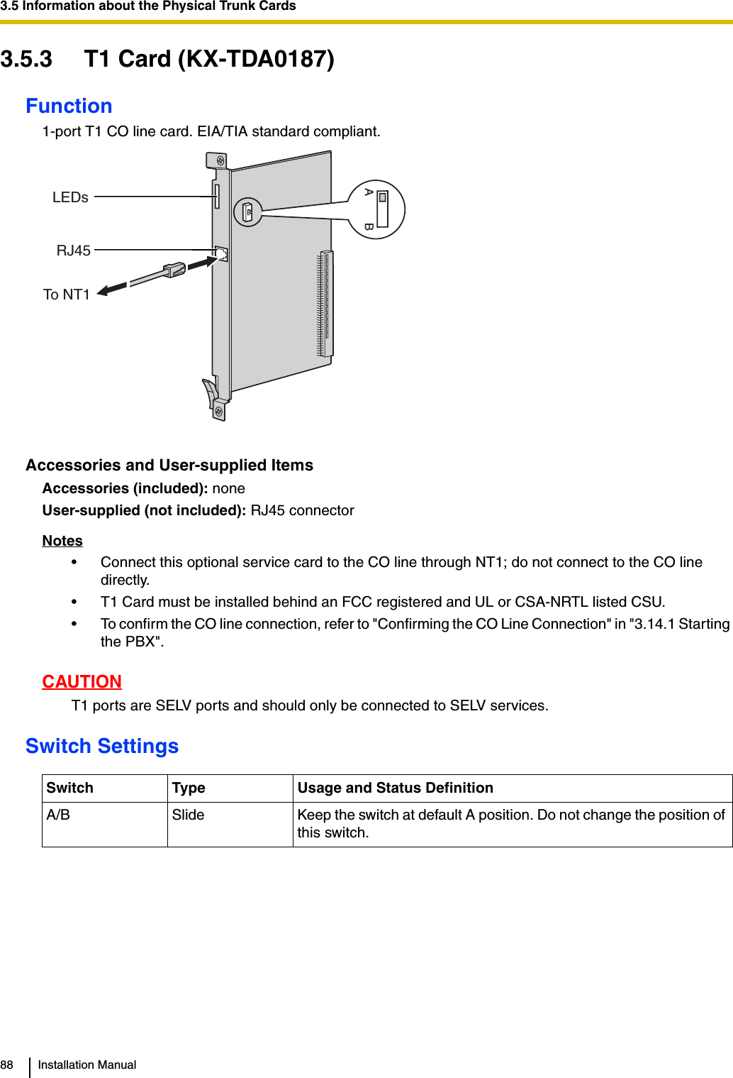
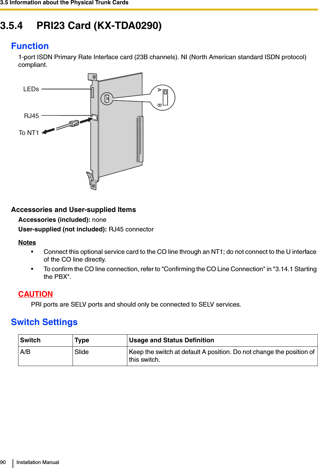
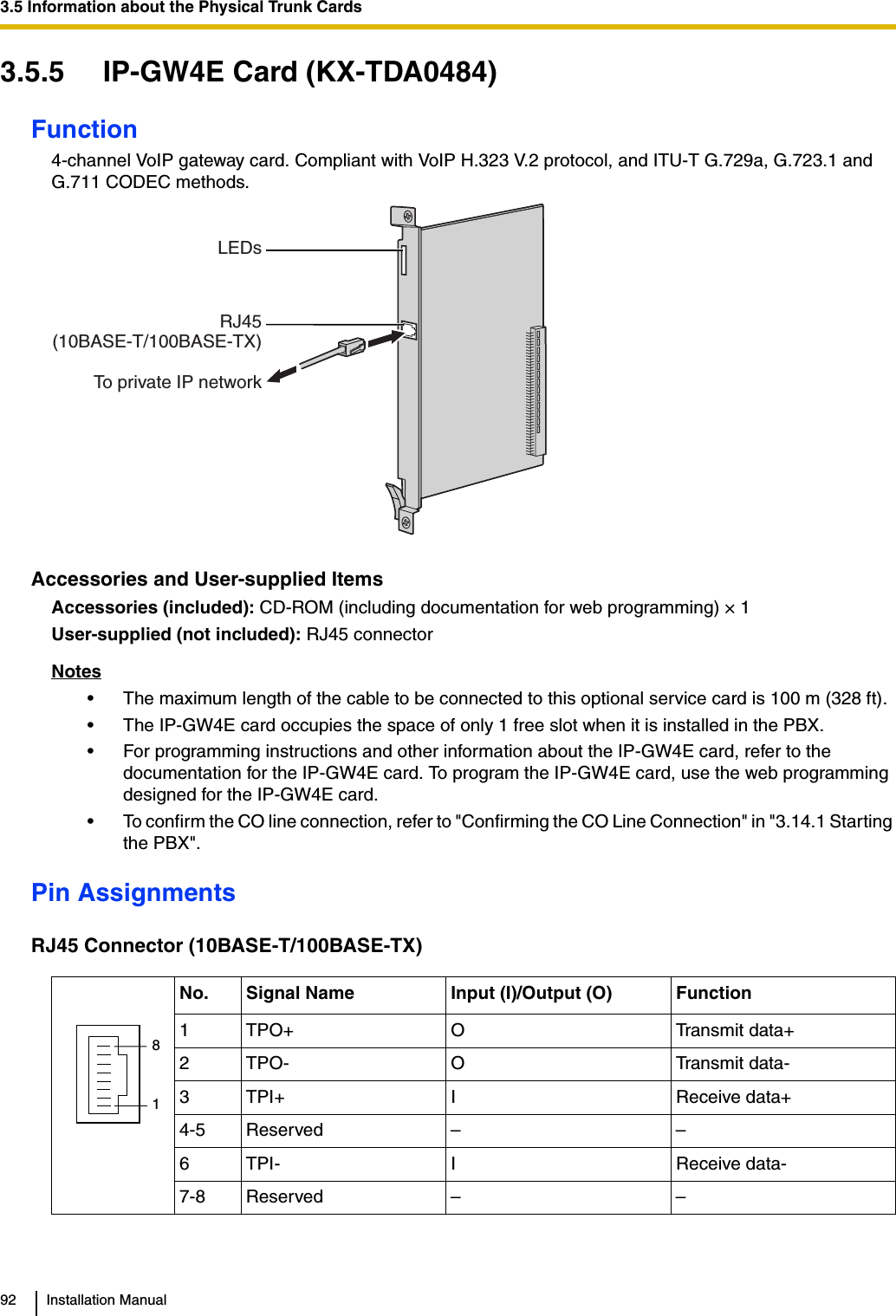
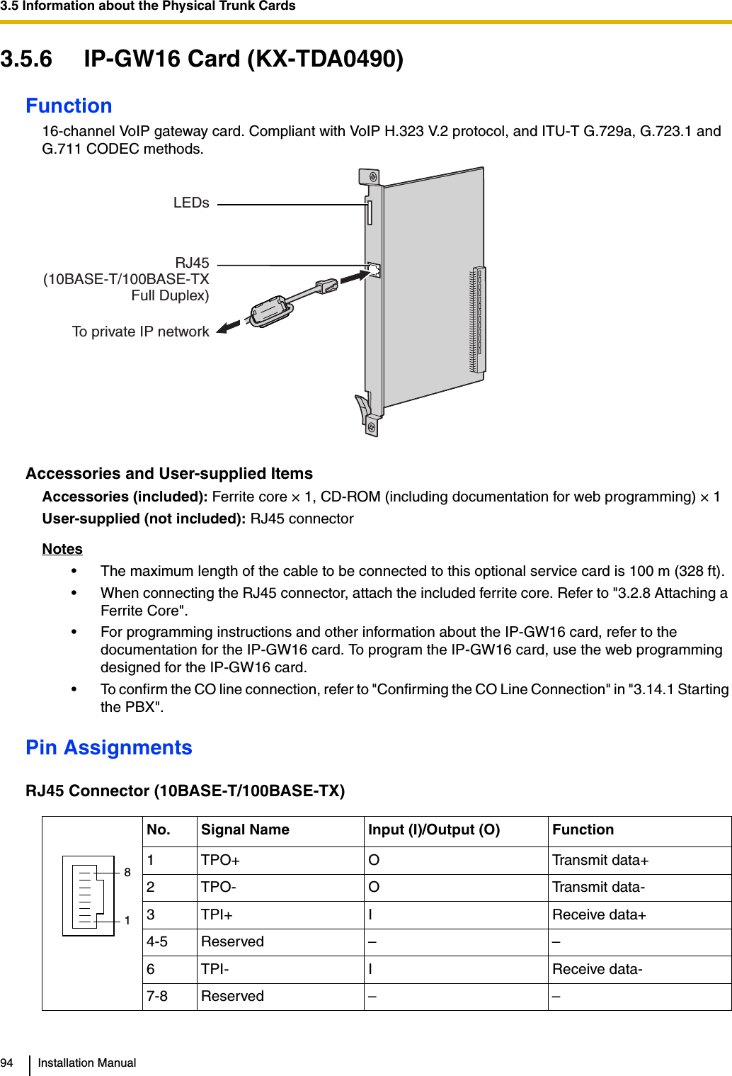
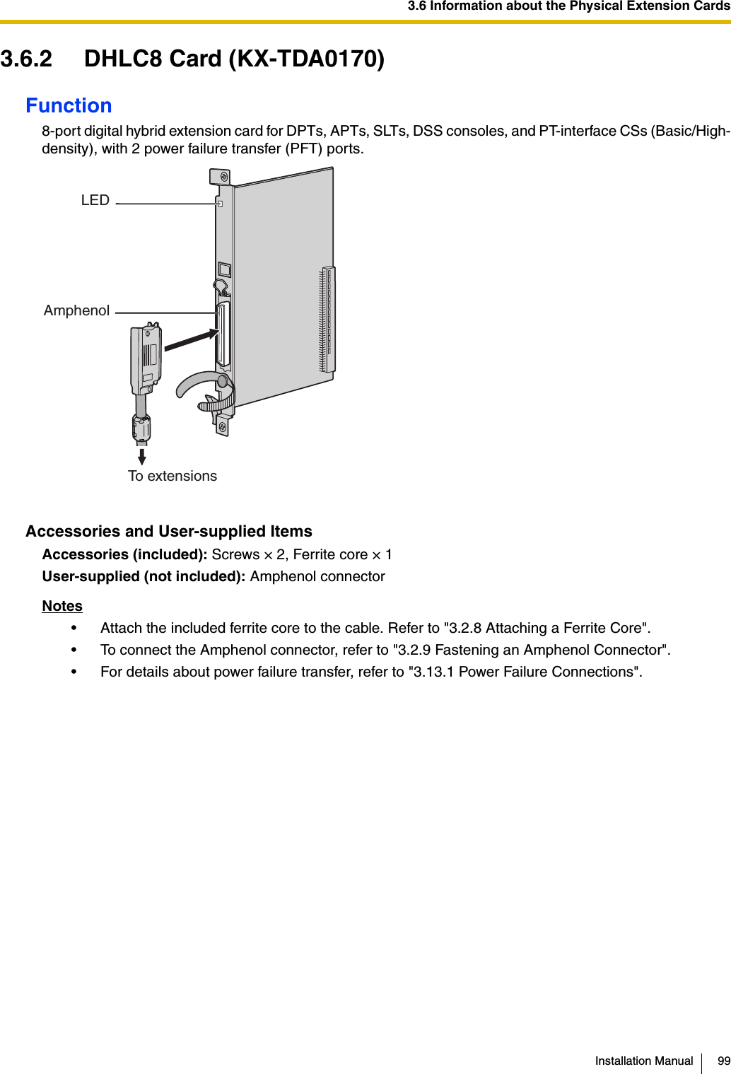
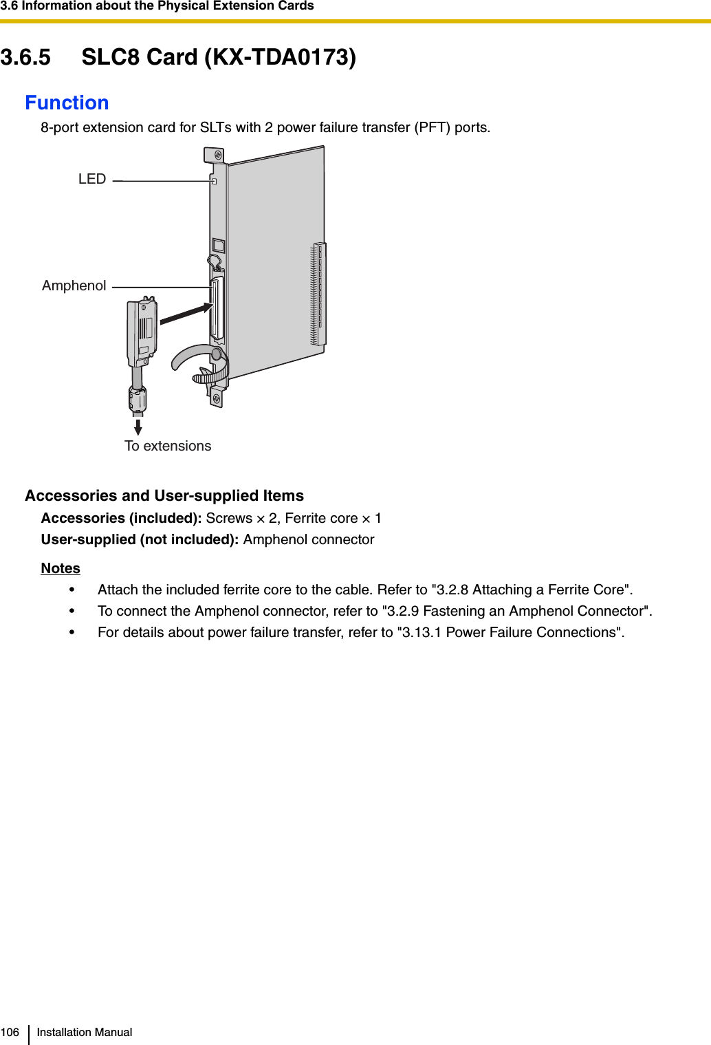
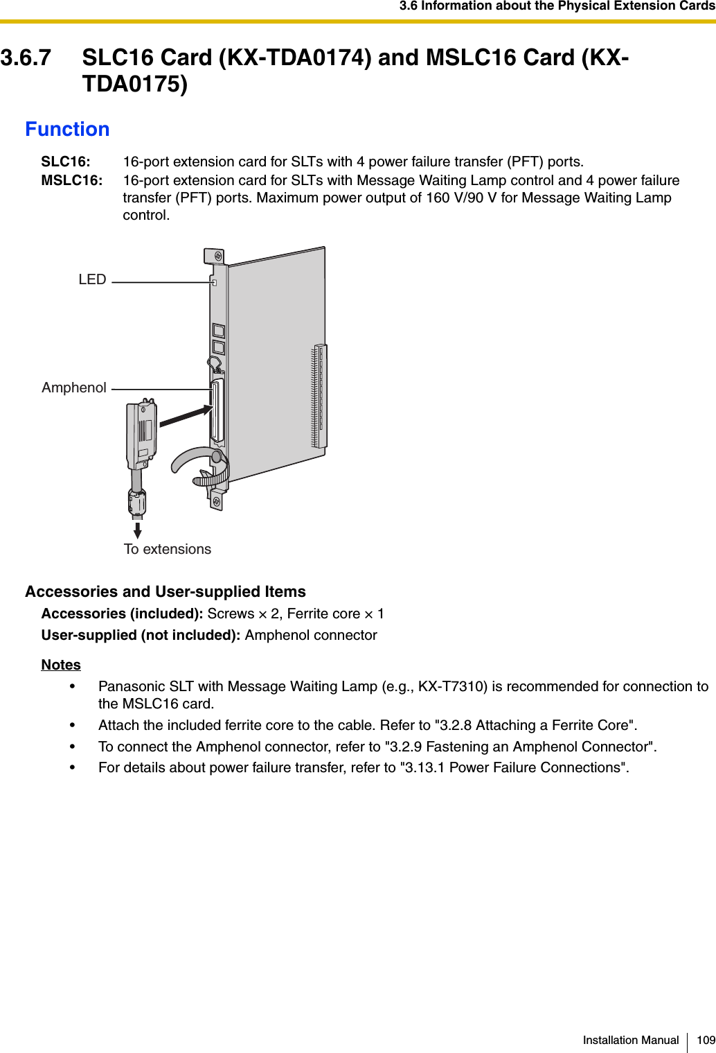
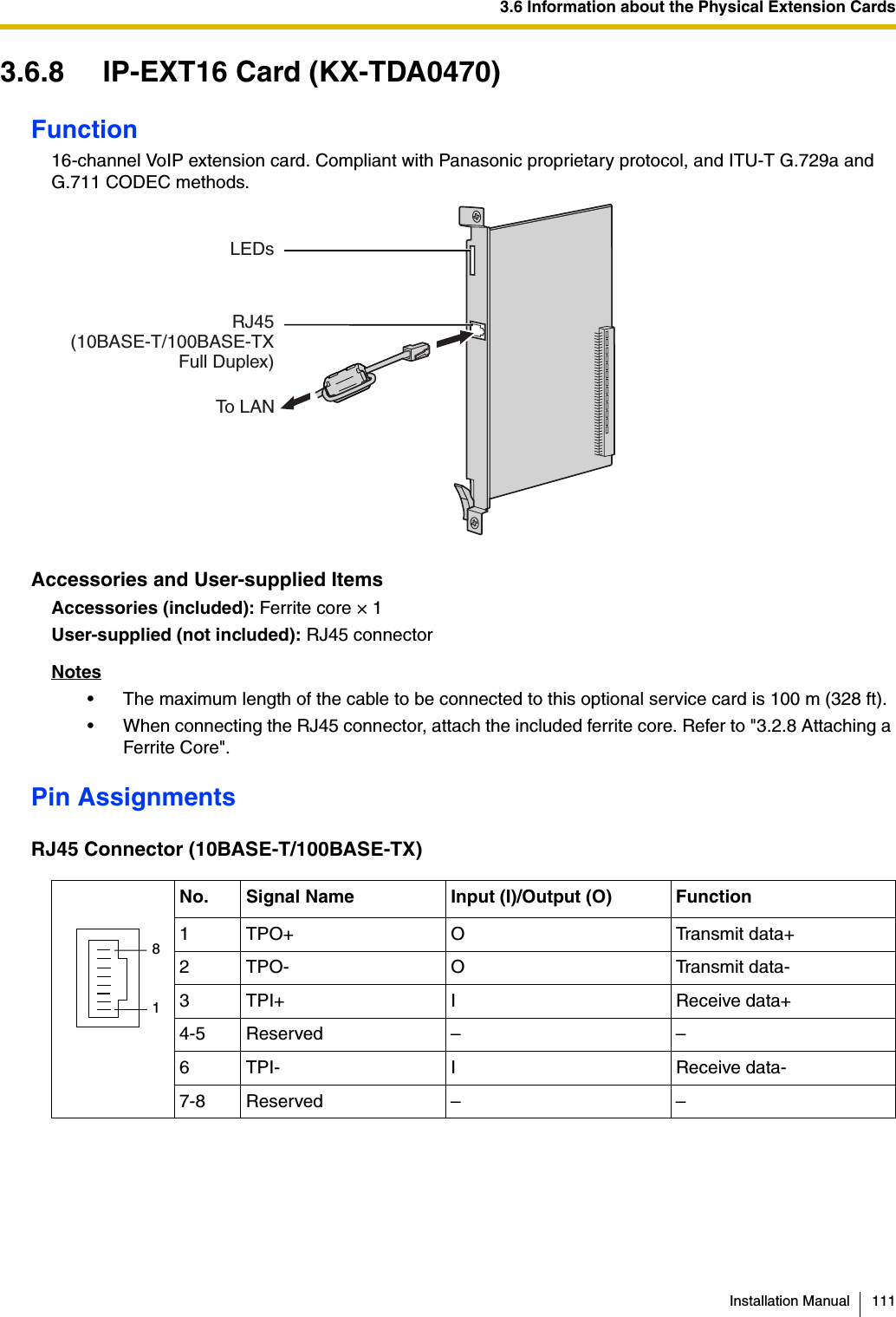
![1.3 Optional Equipment30 Installation ManualNoteFor the maximum number of optional service cards that can be installed in the PBX, refer to "1.4.3 System Capacity".KX-TDA0173 8-Port Single Line Telephone Extension Card (SLC8)8-port extension card for SLTs with 2 power failure transfer (PFT) ports.KX-TDA0174 16-Port Single Line Telephone Extension Card (SLC16)16-port extension card for SLTs with 4 power failure transfer (PFT) ports.KX-TDA0175 16-Port Single Line Telephone Extension with Message Lamp Card (MSLC16)16-port extension card for SLTs with Message Waiting Lamp control and 4 power failure transfer (PFT) ports. Maximum power output of 160 V/90 V for Message Waiting Lamp control.KX-TDA0180 8-Port Analog Trunk Card (LCOT8) 8-port analog CO line card with 2 power failure transfer (PFT) ports.KX-TDA0181 16-Port Analog Trunk Card (LCOT16) 16-port analog CO line card with 4 power failure transfer (PFT) ports.KX-TDA0187 T-1 Trunk Card (T1) 1-port T1 CO line card. EIA/TIA standard compliant.KX-TDA0190 Optional 3-Slot Base Card (OPB3) Optional 3-slot base card for mounting a maximum of 3 option cards from the following: MSG4, DPH4, or ECHO16 card.KX-TDA0191 4-Channel Message Card (MSG4) 4-channel message card. To be mounted on the OPB3 card.KX-TDA0193 8-Port Caller ID Card (CID8) 8-port Caller ID signal type FSK/FSK (with Call Waiting Caller ID [Visual Caller ID])/DTMF. To be mounted on the LCOT8/LCOT16 cards.KX-TDA0196 Remote Card (RMT) Analog modem card for remote communication with the PBX. ITU-T V.90 support. To be mounted on the IPCMPR card.KX-TDA0290 PRI Card (PRI23) 1-port ISDN Primary Rate Interface card (23B channels). NI (North American standard ISDN protocol) compliant.KX-TDA0470 16-Channel VoIP Extension Card (IP-EXT16)16-channel VoIP extension card. Compliant with Panasonic proprietary protocol, and ITU-T G.729a and G.711 CODEC methods.KX-TDA0484 4-Channel VoIP Gateway Card (IP-GW4E)4-channel VoIP gateway card. Compliant with VoIP H.323 V.2 protocol, and ITU-T G.729a, G.723.1 and G.711 CODEC methods.KX-TDA0490 16-Channel VoIP Gateway Card (IP-GW16)16-channel VoIP gateway card. Compliant with VoIP H.323 V.2 protocol, and ITU-T G.729a, G.723.1 and G.711 CODEC methods.Model No. Model Name Description](https://usermanual.wiki/Panasonic-of-North-America/96NKX-TDA1052.users-manual/User-Guide-799956-Page-30.png)


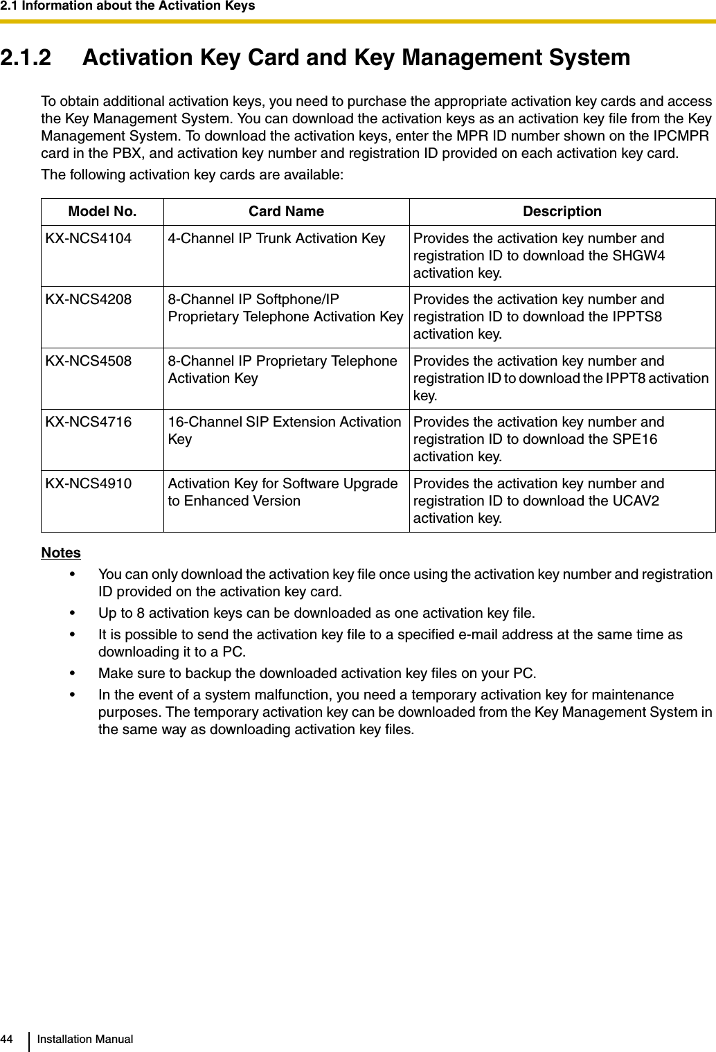


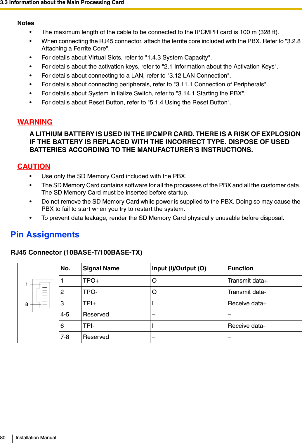
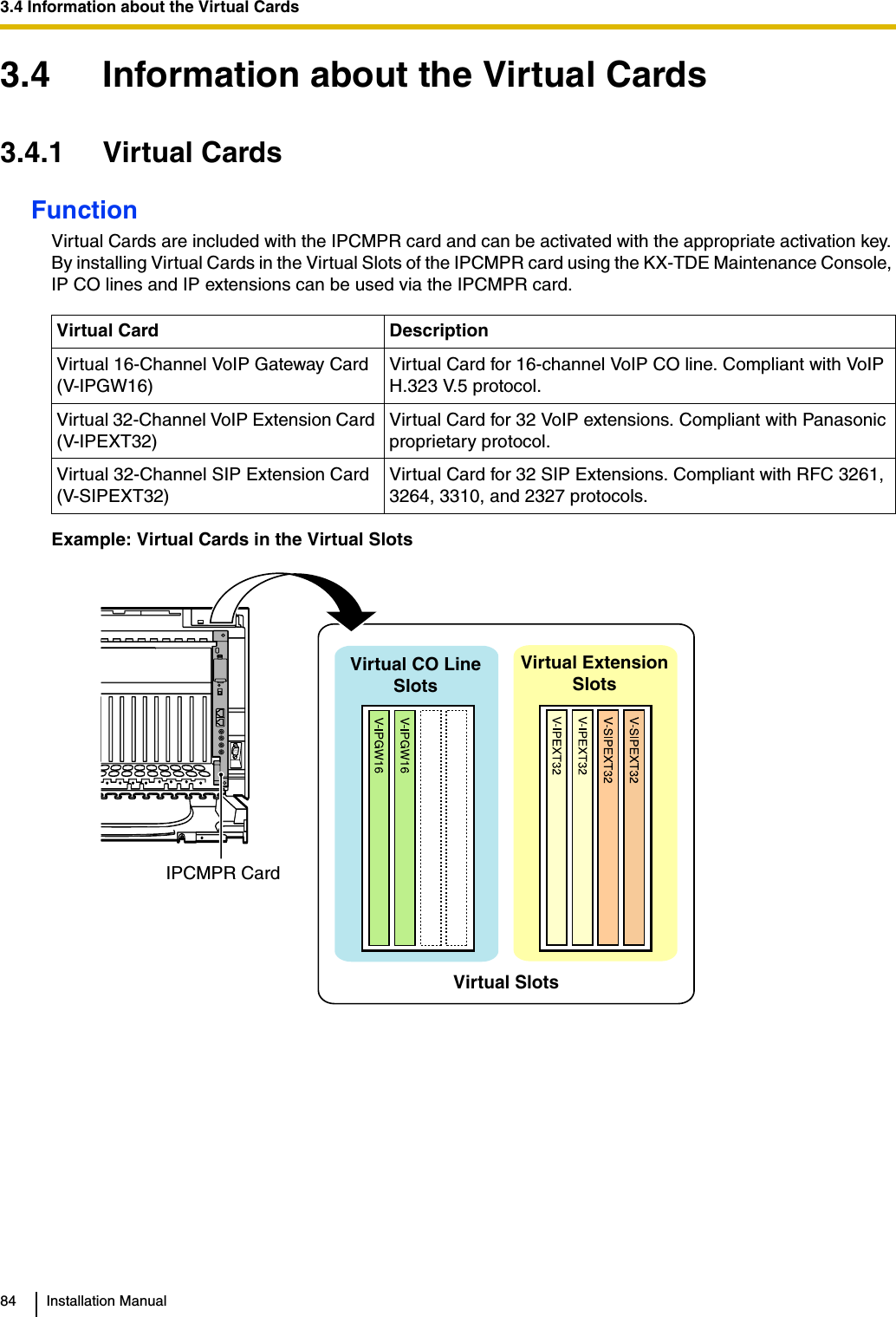
![3.5 Information about the Physical Trunk CardsInstallation Manual 873.5.2 CID8 Card (KX-TDA0193)Function8-port Caller ID signal type FSK/FSK (with Call Waiting Caller ID [Visual Caller ID])/DTMF. To be mounted on the LCOT8/LCOT16 cards.Accessories and User-supplied ItemsAccessories (included): Screws × 2User-supplied (not included): noneNoteOnly 1 CID8 card can be mounted on the LCOT8 card.Switch Settings (on LCOT8/LCOT16 cards)Switch Type Usage and Status DefinitionPort Setting DIP Keep all DIP switches at default "ON" positions. Do not change the positions of these switches.NoteSW2 is for the LCOT16 card only.CID8 CardinsideScrewOFF ON ON OFF SW2LCOT16 card onlySW1](https://usermanual.wiki/Panasonic-of-North-America/96NKX-TDA1052.users-manual/User-Guide-799956-Page-87.png)
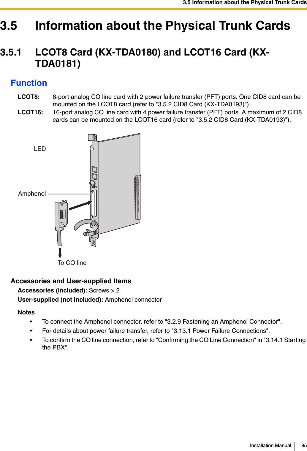
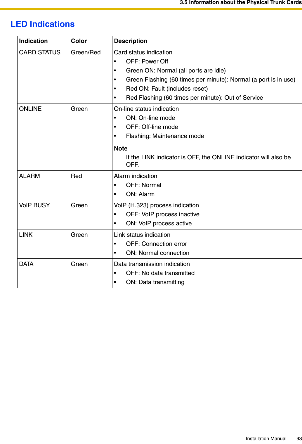
![3.5 Information about the Physical Trunk CardsInstallation Manual 89Pin AssignmentsRJ45 ConnectorLED IndicationsNo. Signal Name Level [V] Function1 RX+ (+) Receive data (+)2 RX- (-) Receive data (-)3 Reserved – –4 TX- (-) Transmit data (-)5 TX+ (+) Transmit data (+)6-8 Reserved – –Indication Color DescriptionCARD STATUS Green/Red Card status indication• OFF: Power Off• Green ON: Normal (all ports are idle)• Green Flashing (60 times per minute): Normal (a port is in use)• Red ON: Fault (includes reset)• Red Flashing (60 times per minute): Out of ServiceSYNC-ERR Red Non-synchronisation status indication• OFF: Normal• ON: Out of synchronisationRAI Red RAI signal status indication• OFF: Normal• ON: Alarm (Clock Slave)• Flashing (60 times per minute): Alarm (Clock Master)AIS Red AIS status indication• OFF: Normal•ON: AlarmSYNC Green Synchronisation status indication• OFF: Not synchronised• ON: Synchronised• Flashing (60 times per minute): Synchronised (Clock Master)81](https://usermanual.wiki/Panasonic-of-North-America/96NKX-TDA1052.users-manual/User-Guide-799956-Page-89.png)
![3.5 Information about the Physical Trunk CardsInstallation Manual 91Pin AssignmentsRJ45 ConnectorLED IndicationsNo. Signal Name Level [V] Function1 RX+ (+) Receive data (+)2 RX- (-) Receive data (-)3 Reserved – –4 TX- (-) Transmit data (-)5 TX+ (+) Transmit data (+)6-8 Reserved – –Indication Color DescriptionCARD STATUS Green/Red Card status indication• OFF: Power Off• Green ON: Normal (all ports are idle)• Green Flashing (60 times per minute): Normal (a port is in use)• Red ON: Fault (includes reset)• Red Flashing (60 times per minute): Out of ServiceSYNC-ERR Red Non-synchronisation status indication• OFF: Normal• ON: Out of synchronisationRAI Red RAI signal status indication• OFF: Normal• ON: Alarm (Clock Slave)• Flashing (60 times per minute): Alarm (Clock Master)AIS Red AIS status indication• OFF: Normal•ON: AlarmSYNC Green Synchronisation status indication• OFF: Not synchronised• ON: Synchronised• Flashing (60 times per minute): Synchronised (Clock Master)D-LINK Green Data link status indication• OFF: Not established• ON: Established81](https://usermanual.wiki/Panasonic-of-North-America/96NKX-TDA1052.users-manual/User-Guide-799956-Page-91.png)

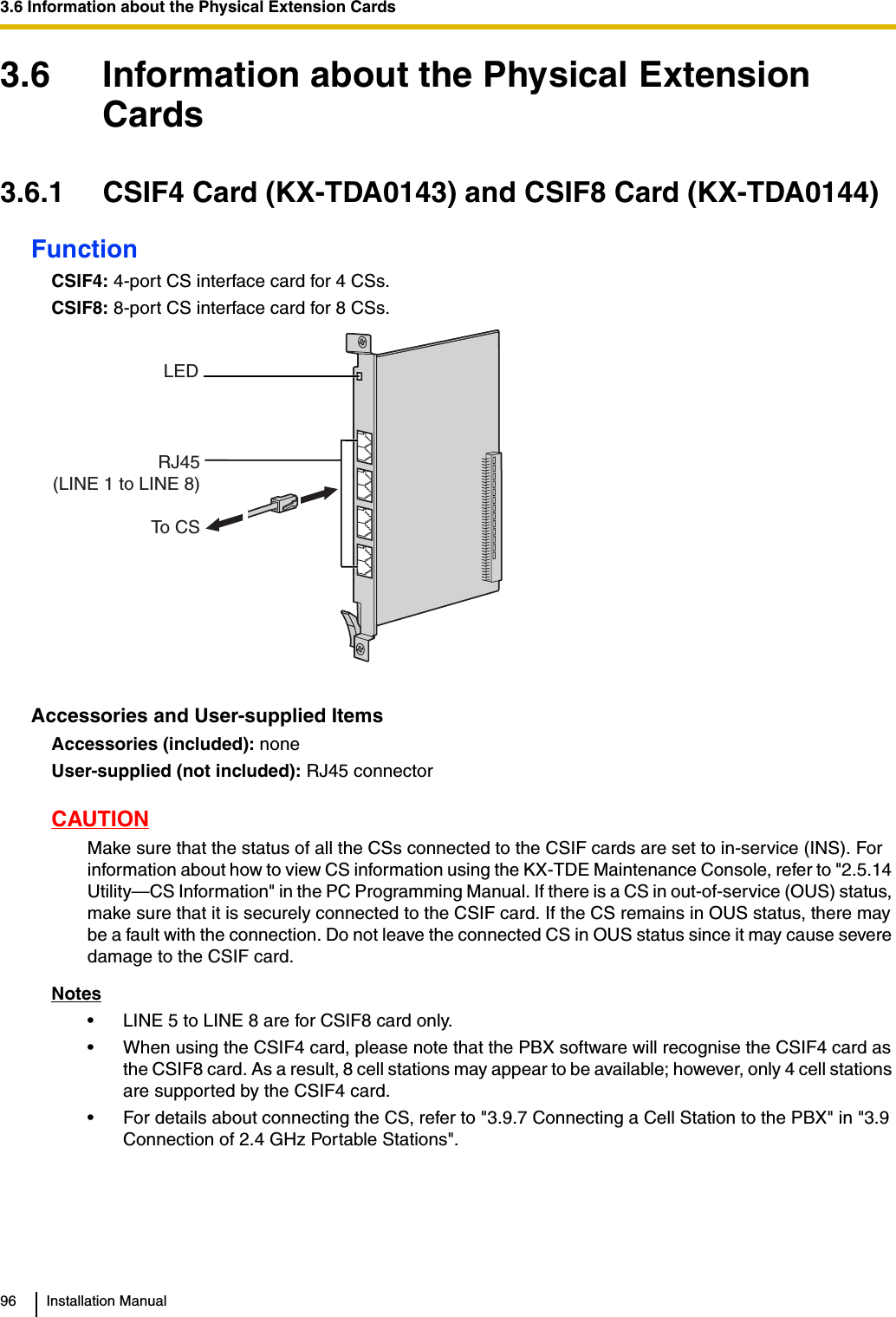
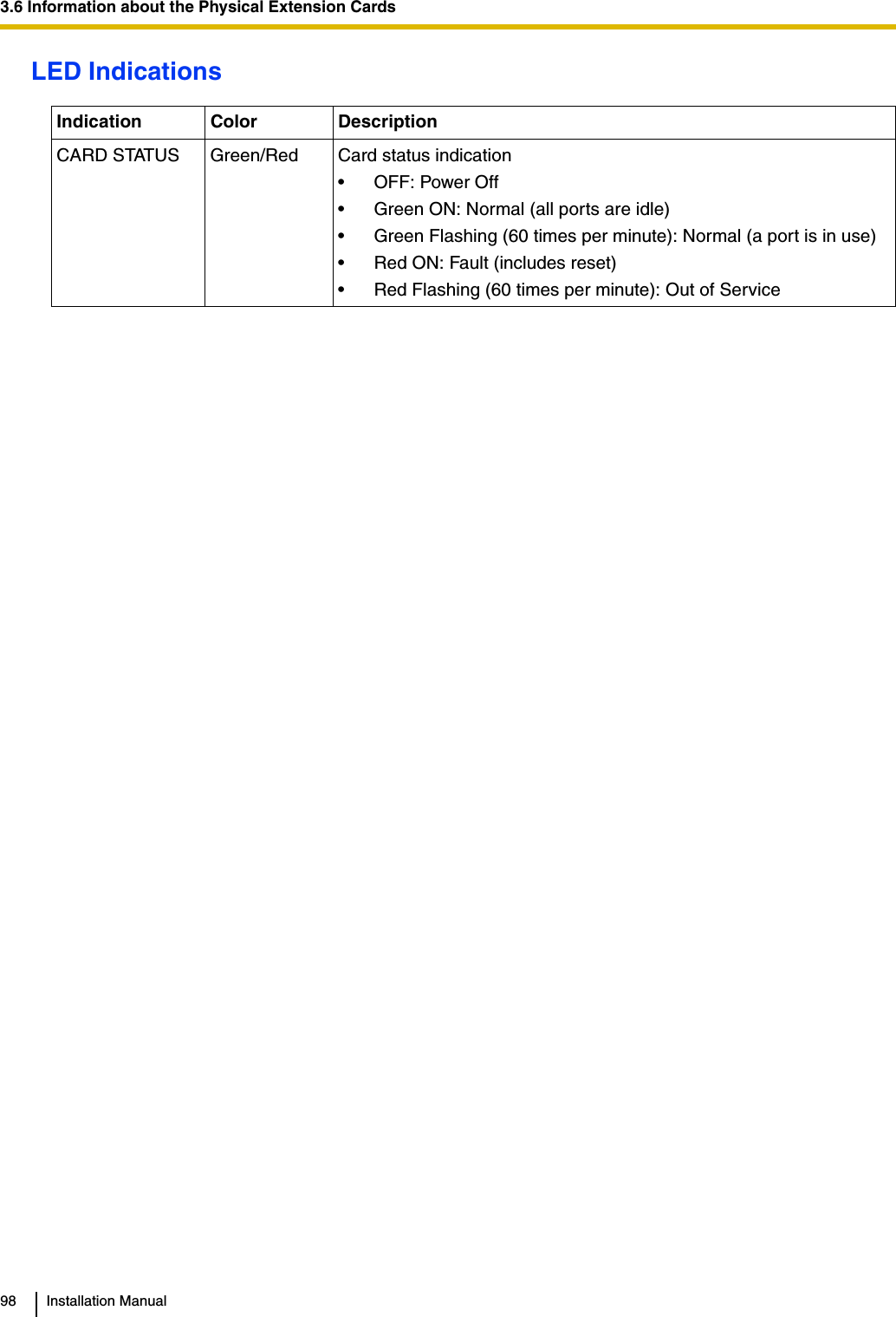
![3.6 Information about the Physical Extension CardsInstallation Manual 101LED IndicationsIndication Color DescriptionCARD STATUS Green/Orange/RedCard status indication• OFF: Power Off• Green ON: Normal (all ports are idle)• Green Flashing (60 times per minute): Normal (a port is in use)• Orange Flashing: Detection of PT-interface CS connection (when starting up the PT-interface CS [Basic/High-density])• Red ON: Fault (includes reset)• Red Flashing (60 times per minute): Out of Service](https://usermanual.wiki/Panasonic-of-North-America/96NKX-TDA1052.users-manual/User-Guide-799956-Page-101.png)
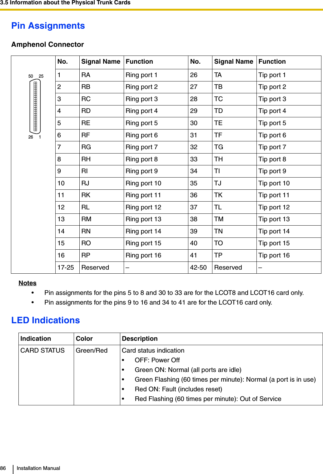
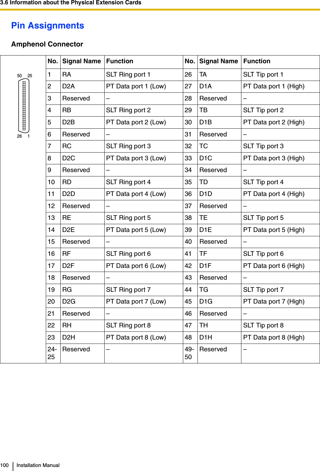
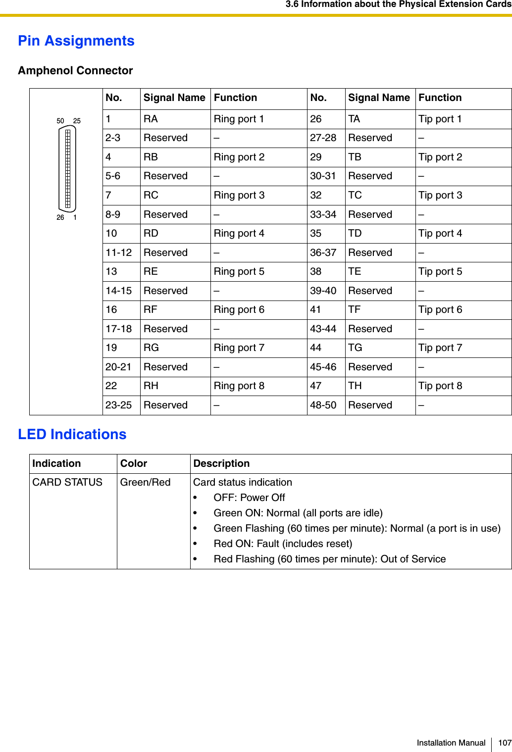
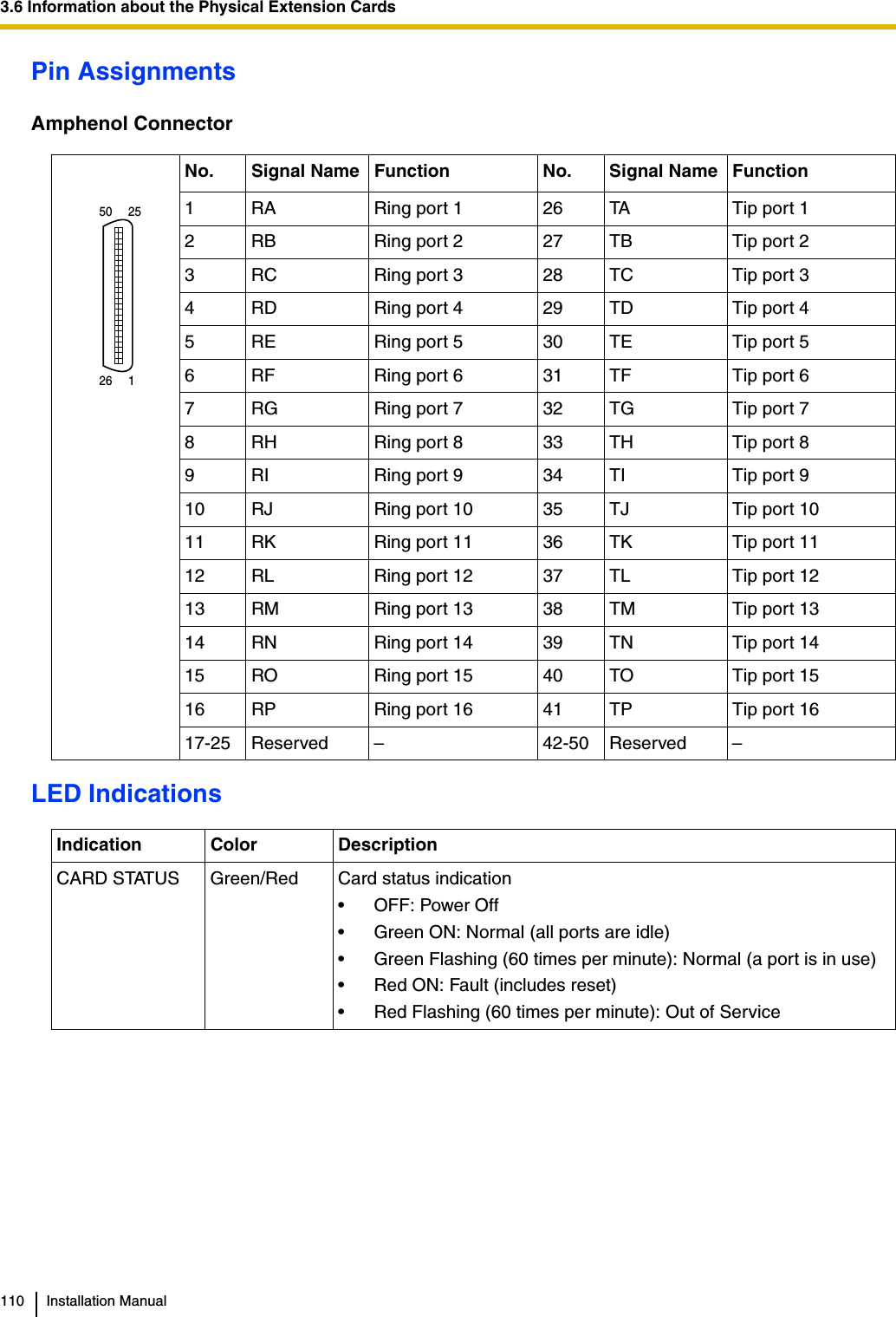
![3.6 Information about the Physical Extension CardsInstallation Manual 103Pin AssignmentsAmphenol ConnectorLED IndicationsNo. Signal Name Function No. Signal Name Function1 Reserved – 26 Reserved –2 D2A Data port 1 (Low) 27 D1A Data port 1 (High)3-4 Reserved – 28-29 Reserved –5 D2B Data port 2 (Low) 30 D1B Data port 2 (High)6-7 Reserved – 31-32 Reserved –8 D2C Data port 3 (Low) 33 D1C Data port 3 (High)9-10 Reserved – 34-35 Reserved –11 D2D Data port 4 (Low) 36 D1D Data port 4 (High)12-13 Reserved – 37-38 Reserved –14 D2E Data port 5 (Low) 39 D1E Data port 5 (High)15-16 Reserved – 40-41 Reserved –17 D2F Data port 6 (Low) 42 D1F Data port 6 (High)18-19 Reserved – 43-44 Reserved –20 D2G Data port 7 (Low) 45 D1G Data port 7 (High)21-22 Reserved – 46-47 Reserved –23 D2H Data port 8 (Low) 48 D1H Data port 8 (High)24-25 Reserved – 49-50 Reserved –Indication Color DescriptionCARD STATUS Green/Orange/RedCard status indication• OFF: Power Off• Green ON: Normal (all ports are idle)• Green Flashing (60 times per minute): Normal (a port is in use)• Orange Flashing: Detection of PT-interface CS connection (when starting up the PT-interface CS [Basic/High-density])• Red ON: Fault (includes reset)• Red Flashing (60 times per minute): Out of Service50 2526 1](https://usermanual.wiki/Panasonic-of-North-America/96NKX-TDA1052.users-manual/User-Guide-799956-Page-103.png)

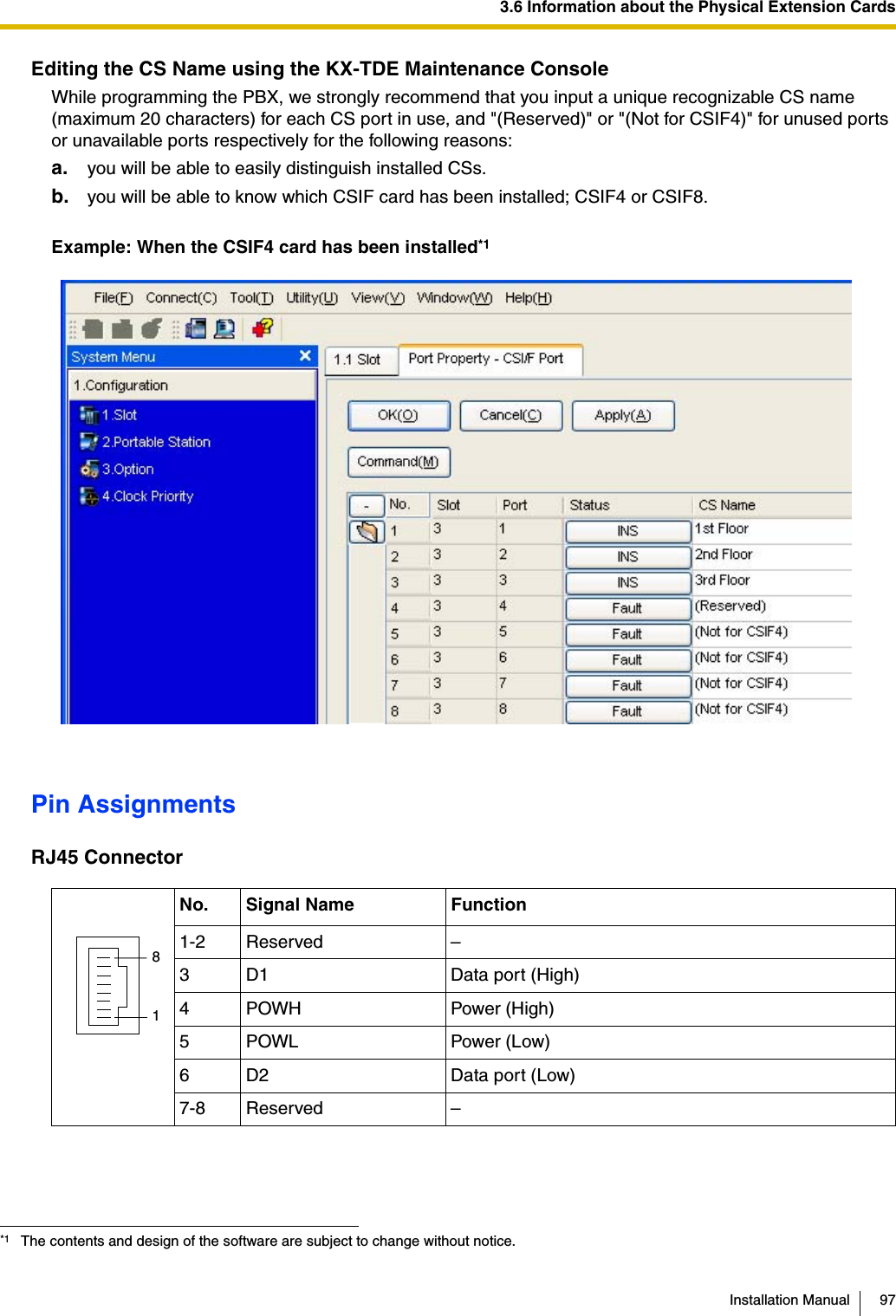
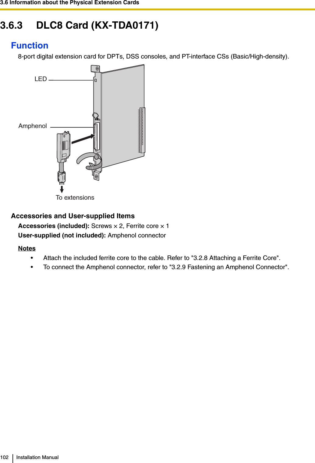
![3.6 Information about the Physical Extension CardsInstallation Manual 105Pin AssignmentsAmphenol ConnectorLED IndicationsNo. Signal Name Function No. Signal Name Function1 D2A Data port 1 (Low) 26 D1A Data port 1 (High)2 D2B Data port 2 (Low) 27 D1B Data port 2 (High)3 D2C Data port 3 (Low) 28 D1C Data port 3 (High)4 D2D Data port 4 (Low) 29 D1D Data port 4 (High)5 D2E Data port 5 (Low) 30 D1E Data port 5 (High)6 D2F Data port 6 (Low) 31 D1F Data port 6 (High)7 D2G Data port 7 (Low) 32 D1G Data port 7 (High)8 D2H Data port 8 (Low) 33 D1H Data port 8 (High)9 D2I Data port 9 (Low) 34 D1I Data port 9 (High)10 D2J Data port 10 (Low) 35 D1J Data port 10 (High)11 D2K Data port 11 (Low) 36 D1K Data port 11 (High)12 D2L Data port 12 (Low) 37 D1L Data port 12 (High)13 D2M Data port 13 (Low) 38 D1M Data port 13 (High)14 D2N Data port 14 (Low) 39 D1N Data port 14 (High)15 D2O Data port 15 (Low) 40 D1O Data port 15 (High)16 D2P Data port 16 (Low) 41 D1P Data port 16 (High)17-25 Reserved – 42-50 Reserved –Indication Color DescriptionCARD STATUS Green/Orange/RedCard status indication• OFF: Power Off• Green ON: Normal (all ports are idle)• Green Flashing (60 times per minute): Normal (a port is in use)• Orange Flashing: Detection of PT-interface CS connection (when starting up the PT-interface CS [Basic/High-density])• Red ON: Fault (includes reset)• Red Flashing (60 times per minute): Out of Service50 2526 1](https://usermanual.wiki/Panasonic-of-North-America/96NKX-TDA1052.users-manual/User-Guide-799956-Page-105.png)
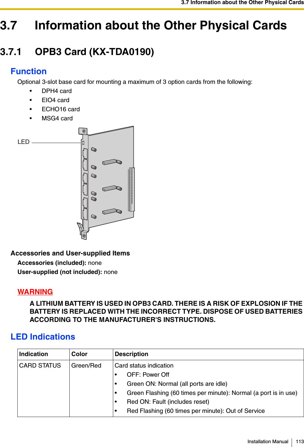

![3.7 Information about the Other Physical CardsInstallation Manual 1193.7.4 ECHO16 Card (KX-TDA0166)Function16-channel card for echo cancellation during conferences. To be mounted on the OPB3 card.Accessories and User-supplied ItemsAccessories (included): Screws × 3User-supplied (not included): noneNoteTo establish a conference call involving 6 to 8 parties, install an ECHO16 card and enable echo cancellation for conferences using the KX-TDE Maintenance Console. For details, refer to "Echo Cancel—Conference" in "2.8.18 [2-9] System Options" of the PC Programming Manual.ScrewinsideECHO16 CardOPB3 Card](https://usermanual.wiki/Panasonic-of-North-America/96NKX-TDA1052.users-manual/User-Guide-799956-Page-119.png)

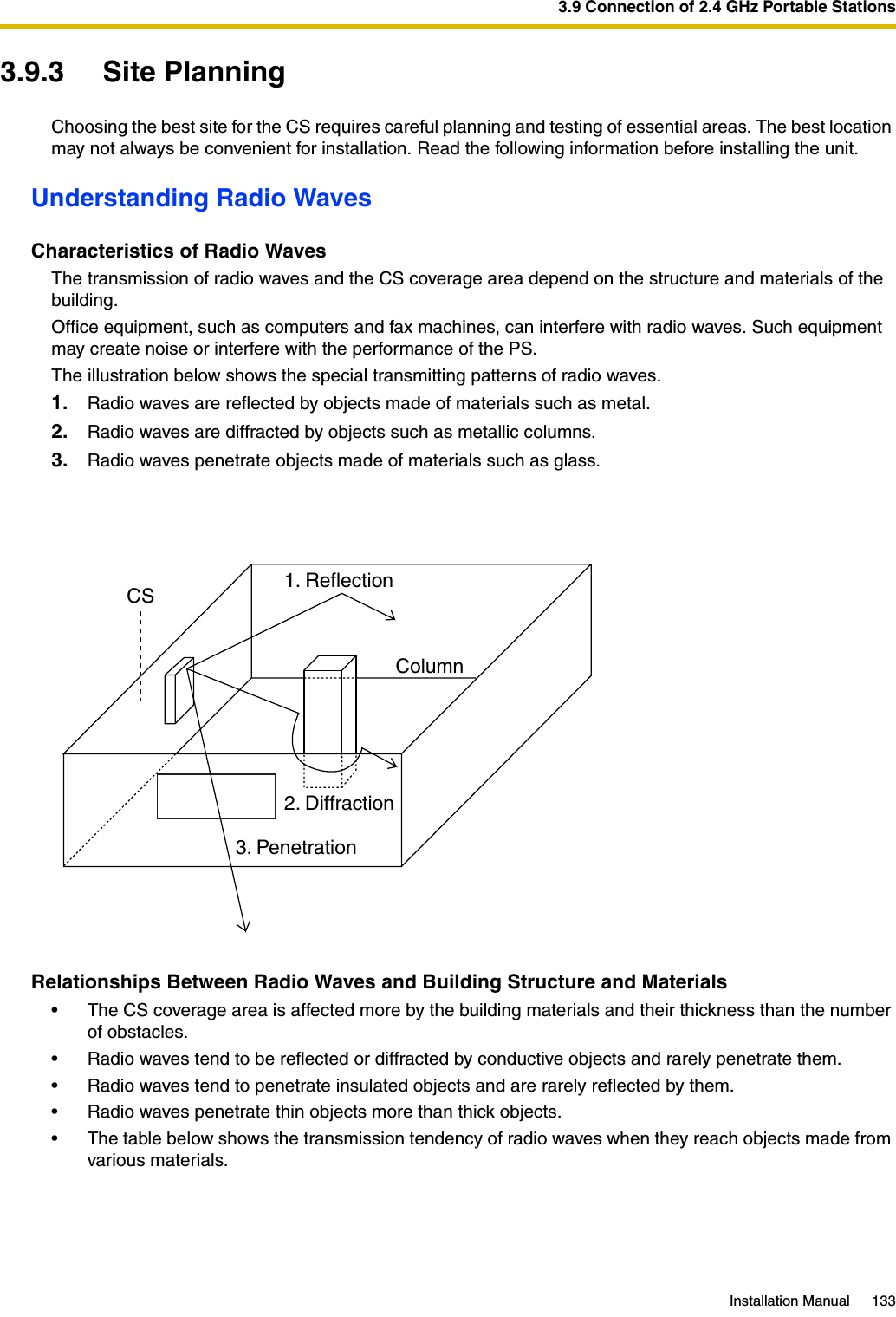
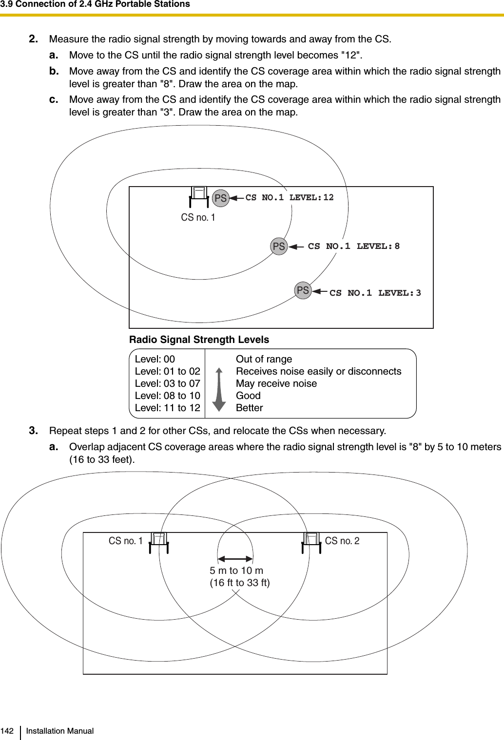
![3.9 Connection of 2.4 GHz Portable StationsInstallation Manual 135CS Coverage AreaThe example below shows the size of the coverage area of 1 CS if it is installed in an area with no obstacles.NoteRadio signal strength levels are measured during the site survey (refer to "3.9.5 Site Survey").Site Survey Preparation1. Obtain a map and investigate the installation site.a. Check the obstacles (e.g., shelves, columns, and partitions).b. Check the materials of the structures (e.g., metal, concrete, and plywood).c. Check the layout and dimensions of the room, corridor, etc.d. Write down the above information on the map.2. Examine the service area required by the user on the map, referring to the following example.a. Draw the coverage area around a CS. Extend the coverage area 30 to 60 meters (98 to 197 feet) in each direction, depending on the materials of the building structures and obstacles in the installation site. Note that a CS cannot be installed outside a building.b. If one CS cannot cover the entire service area, install additional CSs as required. Overlap the coverage areas of adjacent CSs.Where CS coverage areas overlap, the PS will start call handover to the next CS if the signal from ABABCGray Zone:Conversation will be intermittent Out of Service:Cannot make/receive callsGood Coverage AreaRadio signal strengthlevel is greater than "8".(About 30 m to 40 m[98 ft to 131 ft])Good sound qualitycan be maintained.Coverage AreaRadio signal strength level is greater than "3".(About 50 m to 60 m[164 ft to 197 ft])Radio Signal Strength LevelsOut of rangeReceives noise easily or disconnectsMay receive noiseGoodBetterLevel: 00Level: 01 to 02Level: 03 to 07Level: 08 to 10 Level: 11 to 12](https://usermanual.wiki/Panasonic-of-North-America/96NKX-TDA1052.users-manual/User-Guide-799956-Page-135.png)
![3.9 Connection of 2.4 GHz Portable StationsInstallation Manual 151PS RegistrationWhen the PS has not been registered yetWhen registering the PS for the first time, it is possible to select the desired language for the display. (You do not need to enter the PS system programming mode when registering for the first time.)Using the KX-TD7684/KX-TD7685/KX-TD7694/KX-TD7695Using the KX-TD7680Using the KX-TD7690When the PS has already been registered to another PBXOne PS can be registered to a maximum of 4 different PBXs.Using the KX-TD7684/KX-TD7685/KX-TD7694/KX-TD7695Using the KX-TD7680Using the KX-TD7690[690]001 to 128PS No.1 to 4 digits ENDENTER ENTERTo the PSoperationbelowExtn. No.Press POWER for 2 seconds.Select the desired language.Press "F" for 2 seconds.C.Tone C.TonePressPOWER for2 seconds.Press S3 for 2 seconds.C.TonePress S2 repeatedly to select the desired language.[ F2 ][ F3 ]PressPOWER for2 seconds.Press S3 for 2 seconds.C.TonePress S2 repeatedlyto select the desiredlanguage.F2 F3Choose "Base 1–4".Select "Register H/set".C.ToneChoose "SYSTEM 1–4".Select "REGISTRATION".C.ToneChoose "SYSTEM 1–4".Select "REGISTRATION".S1S1SEL SELC.Tone](https://usermanual.wiki/Panasonic-of-North-America/96NKX-TDA1052.users-manual/User-Guide-799956-Page-151.png)

![3.9 Connection of 2.4 GHz Portable StationsInstallation Manual 153Setting the Personal Identification Number (PIN) for PS RegistrationTo prevent registering the PS to a wrong PBX, a PIN for PS registration can be set to the PBX. Before registering the PS to the PBX, enter the PIN set to the PBX into the PS. By doing so, the PS will only be registered to the PBX with the matching PIN.Notes• By default, the PIN for PS registration is "1234" for both the PBX and PS. Therefore, the PS can be registered to the PBX without setting the PIN.• The PIN for PS registration will only be used when registering the PS to the PBX. Therefore, during normal operation after registration, even if there is more than 1 PBX with the same PIN near the PS, the PS will not be inadvertently linked to a different PBX.Setting the PIN for PBXSetting the PIN for PSUsing the KX-TD7684/KX-TD7685/KX-TD7694/KX-TD7695Using the KX-TD7680Using the KX-TD7690[692]4 digitsPIN for PS RegistrationENDENTER ENTER1234Select "Change PIN"1 to 8 digits1234C.TonePIN for PS RegistrationSelect "CHANGE PIN"C.Tone1 to 4 digits1234PIN for PS RegistrationSelect "CHANGE PIN"S1ENTRS1SELC.Tone1 to 4 digits1234PIN for PS Registration](https://usermanual.wiki/Panasonic-of-North-America/96NKX-TDA1052.users-manual/User-Guide-799956-Page-153.png)
![3.9 Connection of 2.4 GHz Portable Stations154 Installation ManualPS TerminationConfirm the following before cancelling the PS registration:• The PS is turned on.• The PS is within range.If the registration information is still stored in the PSUsing the KX-TD7684/KX-TD7685/KX-TD7694/KX-TD7695Using the KX-TD7680Using the KX-TD7690Testing the OperationWalk around the service area while having a conversation using a registered PS. If noise is frequent or conversations disconnect, relocate the CSs or install an additional CS.[691]001 to 128PS No.ENTER ENTERENDTo the PSoperationbelowIf "Rejected" or "Time out" is displayedCLEAR YESPress "YES".Press "CLEAR".Select "Base 1-4".Select "YES".C.ToneSelect "Cancel Base".Select the desired item.Select "DELETESYSTEM".Select "YES".C.ToneSelect the desired item.Select "DELETESYSTEM".S1S1SEL SELSelect "YES".C.ToneS1SEL](https://usermanual.wiki/Panasonic-of-North-America/96NKX-TDA1052.users-manual/User-Guide-799956-Page-154.png)


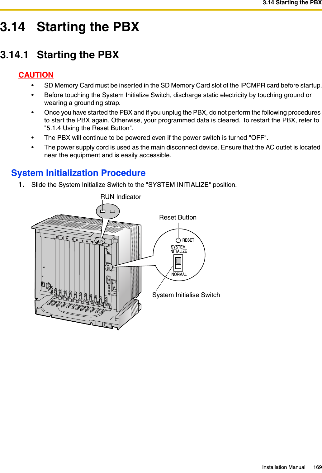
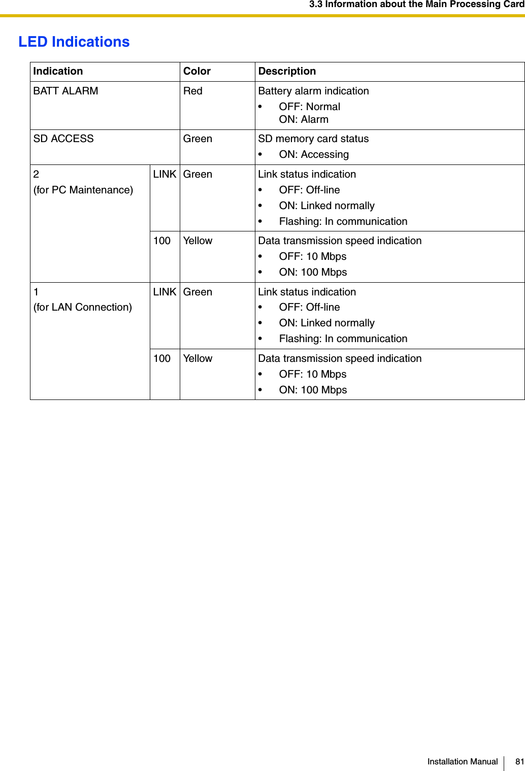
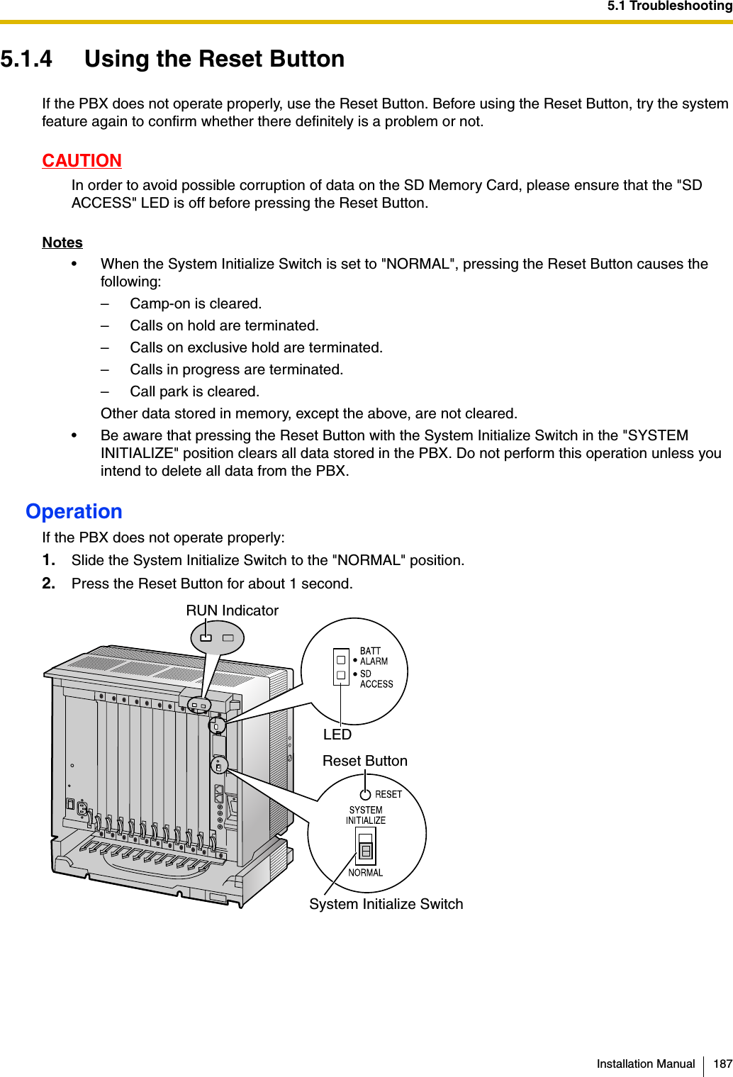
![3.14 Starting the PBX170 Installation Manual2. Plug the AC power cord into the PBX and an AC outlet, and turn on the PBX. The RUN indicator will flash.NoteFor safety reasons, do not stretch, bend, or pinch the AC power cord.3. While the RUN indicator is flashing, slide the System Initialize Switch back to the "NORMAL" position. Depending on the configuration, initialization takes about 1 min to 3 min. If successfully executed, the RUN indicator will stop flashing and stay lit.All data will be cleared, and the PBX as well as all optional service cards (except for the IP-GW card) will be initialized to the default values. The DPTs should show the time as 01:00.The data of the IP-GW card will not be initialized.NoteUse only the AC power cord included with the PSU.LED IndicationsConfirming the CO Line ConnectionAfter initialization, program the PBX and connect CO lines to the PBX.To confirm that the CO lines are successfully connected, dial [ ] [3] [7] + CO line number (3 digits) on a PT, or press the PT's S-CO button. You will hear a dial tone if the CO line is available and connected.Indication Color DescriptionRUN Green PBX status indication• OFF: Power Off (includes normal reset)• ON: Power On and running (on-line)• Flashing (60 times per minute): Starting up• Flashing (120 times per minute): Starting up or resetting with:• the System Initialize Switch in "SYSTEM INITIALIZE" position• the SD Memory Card not insertedALARM Red Alarm indication• OFF: Normal• ON: Alarm (CPU stop, alarm for each optional service card)• Flashing: Alarm (IPCMPR file error in restarting)To AC Outlet](https://usermanual.wiki/Panasonic-of-North-America/96NKX-TDA1052.users-manual/User-Guide-799956-Page-170.png)


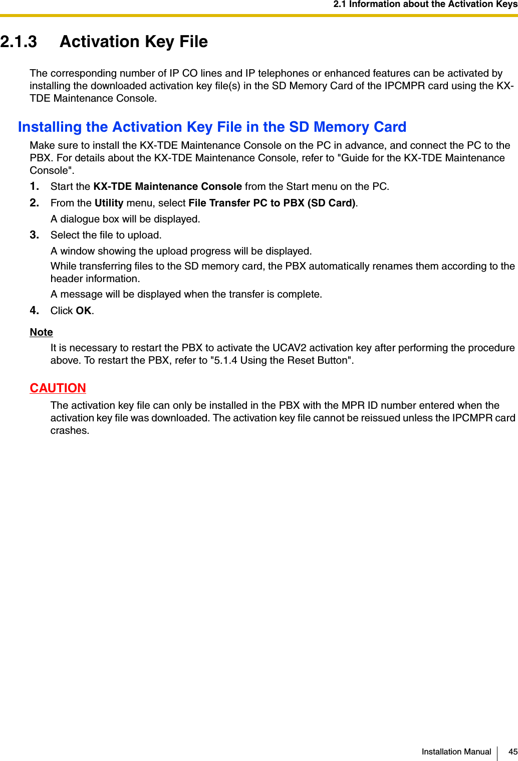
![IndexInstallation Manual 193IInformation about the Virtual Cards 84Installation Precautions 48IP Convergence Main Processing Card (IPCMPR Card) 79IPCMPR Card 79IPCMPR Card Slot 34IP-EXT16 Card (KX-TDA0470) 111IP-GW16 Card (KX-TDA0490) 94IP-GW4E Card (KX-TDA0484) 92KKey Management System 44KX-A258 (Blank Slot Cover) 61KX-NCS4104 (4-Channel IP Trunk Activation Key) 44KX-NCS4208 (8-Channel IP Softphone/IP Proprietary Telephone Activation Key) 44KX-NCS4508 (8-Channel IP Proprietary Telephone Activation Key) 44KX-NCS4716 (16-Channel SIP Extension Activation Key) 44KX-NCS4910 (Activation Key for Software Upgrade to Enhanced Version) 44KX-TDA0103 (L-Type Power Supply Unit) 29, 54KX-TDA0104 (M-Type Power Supply Unit) 29, 54KX-TDA0108 (S-Type Power Supply Unit) 29, 54KX-TDA0143 (4 Cell Station Interface Card) 29, 96KX-TDA0144 (8 Cell Station Interface Card) 29, 96KX-TDA0161 (4-Port Doorphone Card) 29, 114KX-TDA0164 (4-Port External Input/Output Card) 29, 116KX-TDA0166 (16-Channel Echo Canceller Card) 29, 119KX-TDA0168 (Extension Caller ID Card) 29, 108KX-TDA0170 (8-Port Digital Hybrid Extension Card) 29, 99KX-TDA0171 (8-Port Digital Extension Card) 29, 102KX-TDA0172 (16-Port Digital Extension Card) 29, 104KX-TDA0173 (8-Port Single Line Telephone Extension Card) 30, 106KX-TDA0174 (16-Port Single Line Telephone Extension Card) 30, 109KX-TDA0175 (16-Port Single Line Telephone Extension with Message Lamp Card) 30, 109KX-TDA0180 (8-Port Analog Trunk Card) 30, 85KX-TDA0181 (16-Port Analog Trunk Card) 30, 85KX-TDA0187 (T-1 Trunk Card) 30, 88KX-TDA0190 (Optional 3-Slot Base Card) 30, 113KX-TDA0191 (4-Channel Message Card) 30, 120KX-TDA0193 (8-Port Caller ID Card) 30, 87KX-TDA0196 (Remote Card) 30, 83KX-TDA0290 (PRI Card [PRI23]) 30, 90KX-TDA0470 (16-Channel VoIP Extension Card) 30, 111KX-TDA0484 (4-Channel VoIP Gateway Card) 30, 92KX-TDA0490 (16-Channel VoIP Gateway Card) 30, 94KX-TDE Maintenance Console, Connection 173KX-TDE Maintenance Console, Installation 175KX-TDE Maintenance Console, Overview 172KX-TDE Maintenance Console, Quick Setup 175KX-TDE Maintenance Console, System Requirements 175KX-TDE0110 (16-Channel VoIP DSP Card) 29, 82KX-TDE0111 (64-Channel VoIP DSP Card) 29, 82LLCOT16 Card (KX-TDA0181) 85LCOT8 Card (KX-TDA0180) 85LED Indications, PBX 170Load Figure Calculation 38L-Type Power Supply Unit (KX-TDA0103) 29, 54MMaintenance Console 172Master DPT, Digital XDP 126MOH 163MSG4 Card (KX-TDA0191) 120MSLC16 Card (KX-TDA0175) 109M-Type Power Supply Unit (KX-TDA0104) 29, 54NNames and Locations 51OOPB3 Card (KX-TDA0190) 113Optional 3-Slot Base Card (KX-TDA0190) 30, 113Optional Equipment 29Optional Service Card, Installation 59Optional Service Card, Maximum Number 35Optional Service Card, Removal 63PPager 163Panasonic Proprietary Telephones, Compatible 4Panasonic Proprietary Telephones, Incompatible 4Parallel Connection of the Extensions 123Parallel Connection, Using a Modular T-Adaptor 124Parallel Connection, Using an EXtra Device Port 124Parallel Mode 124, 126Password Security 10PC Connection (via RS-232C) 163PC Connection (via USB version 2.0) 162Peer-to-peer Connection 23Physical CO Line Card 35Physical Extension Card 35Power Failure Connections 167Power Supply Unit 54Power Supply Unit Selection 38Power Supply Unit, Installation 55Power Supply Unit, Replacement 56PRI Card (PRI23) (KX-TDA0290) 30, 90PRI23 Card (KX-TDA0290) 90Printer Connection (via RS-232C) 163PSU 54PSU Capacity 39PSU-L 38, 54PSU-M 38, 54PSU-S 38, 54QQuick Setup 175RRadio Method, 2.4 GHz Portable Station 129Remote Card (KX-TDA0196) 30, 83Reset Button 187RMT Card (KX-TDA0196) 83](https://usermanual.wiki/Panasonic-of-North-America/96NKX-TDA1052.users-manual/User-Guide-799956-Page-193.png)