Panasonic of North America 11BT1301 Transmitter Module User Manual OI Manual SC HTB770 RQT9778 P 121012
Panasonic Corporation of North America Transmitter Module OI Manual SC HTB770 RQT9778 P 121012
Contents
- 1. OI Manual_SC-HTB370_RQT9777-P_121011
- 2. OI Manual_SC-HTB770_RQT9778-P_121012
OI Manual_SC-HTB770_RQT9778-P_121012


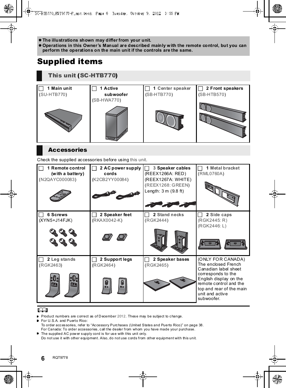
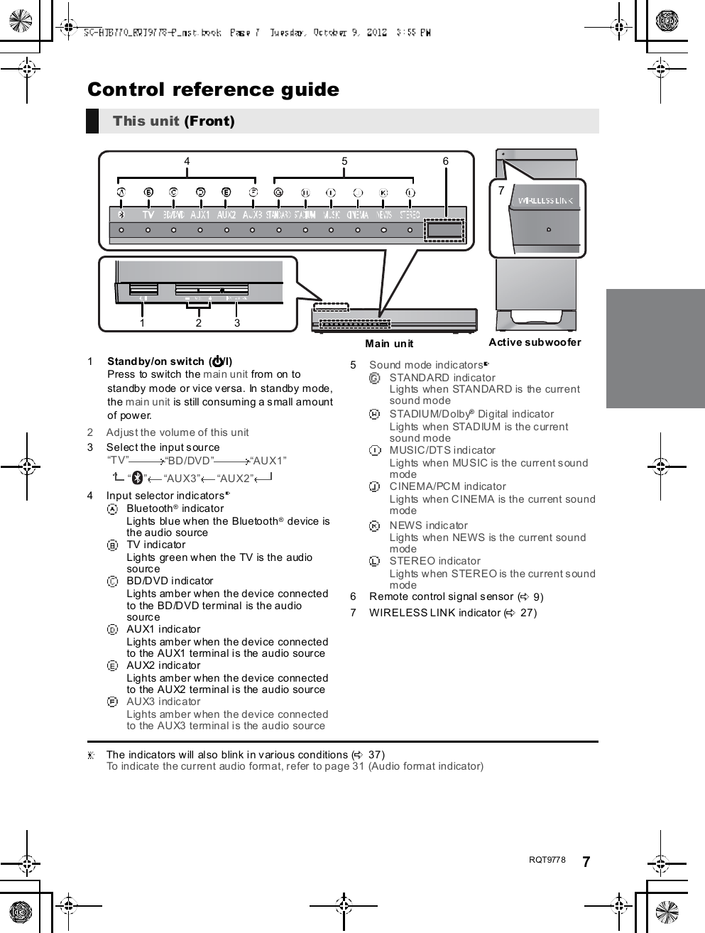
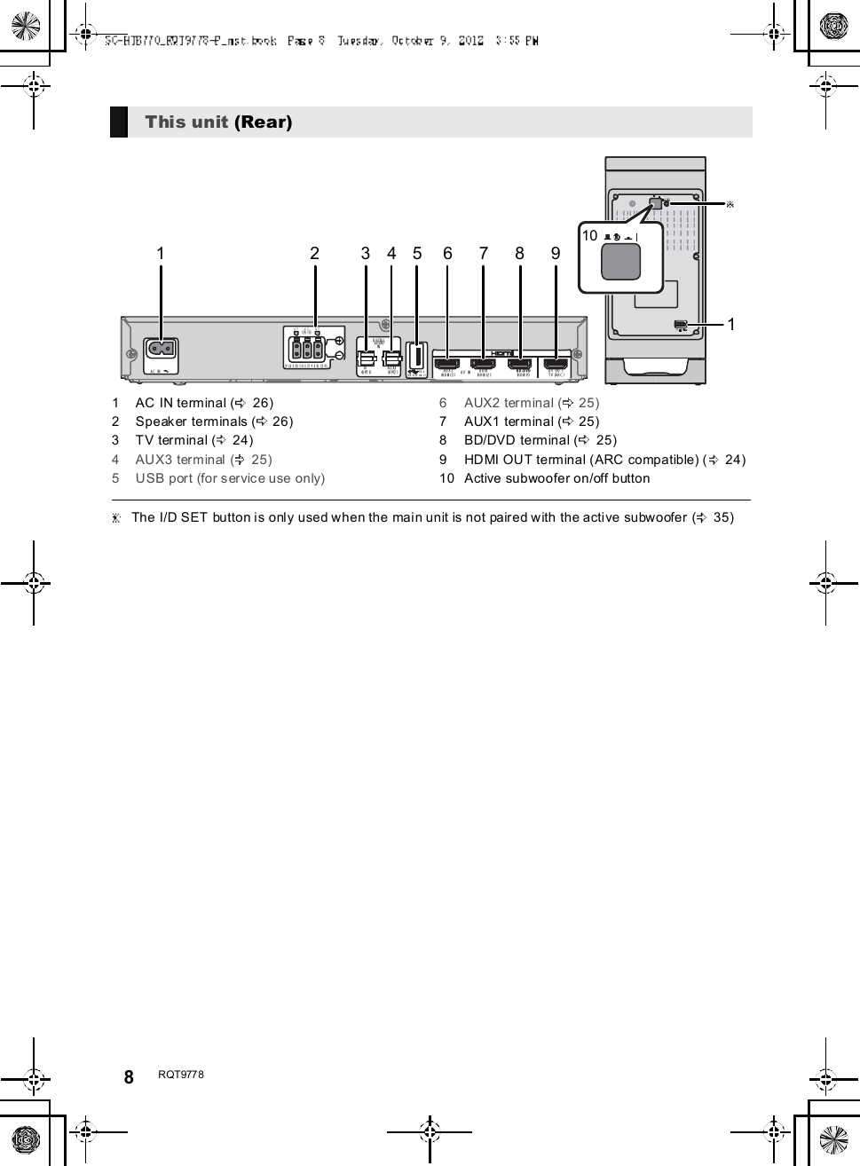
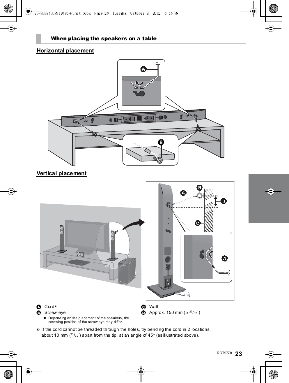
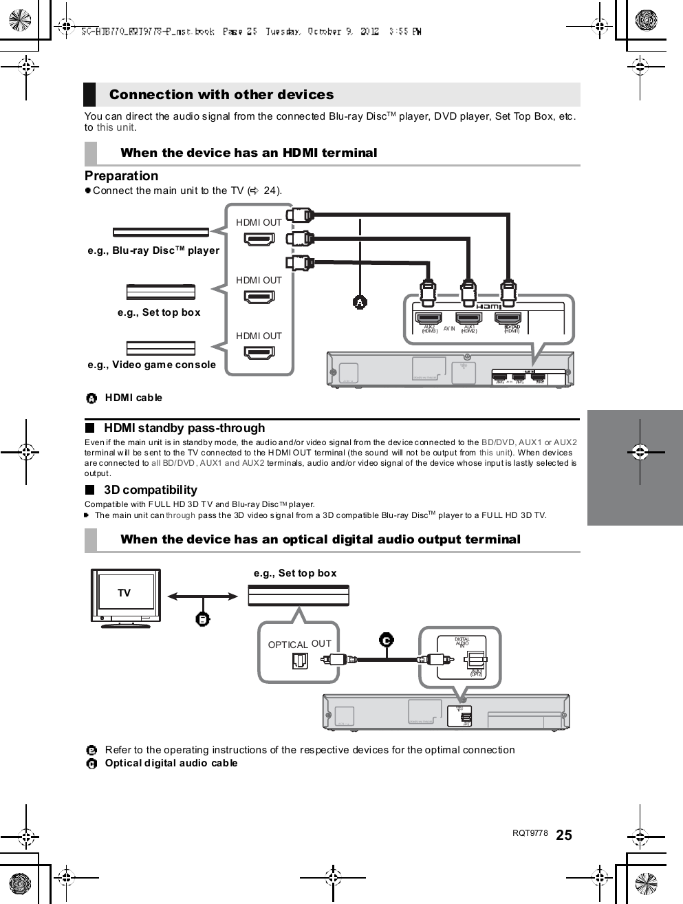
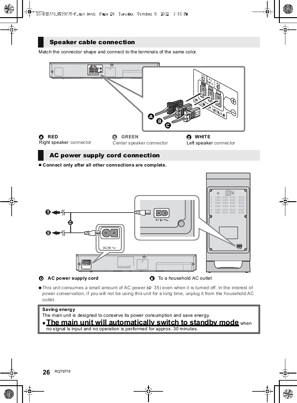
![24 R QT977 8Step 3 ConnectionsTurn off all equipment before connection and read the appropriate owners manual.Do not connect the AC power supply cord until all other connections are complete.HDMIThe HDMI connection supports VIERA Link HDAVI Control ( 30) when used with a compatible Panasonic TV.Use the High Speed HDMI Cables. It is recommended that you use Panasonics HDMI cable.Recommended part number (High Speed HDMI cable):RP -CDHS15 (1.5 m/4.9 ft), RP -CDHS 30 (3.0 m/9.8 ft), RP-CDHS 50 (5.0 m/16.4 ft), et c.Non-HDMI-compliant cables cannot be utilized.Verify if the TVs HDMI terminal is labeled HDMI (ARC).What is ARC?ARC is an abbreviation of Audio Return Channel, also known as H DMI ARC. It refers to one of the HDMI functions. When youconnect the main unit to the terminal labeled HDMI (ARC)on the TV, the optical digital audio cable that is usually required inorder to listen to sound from a TV is no longer required, and TV pictures and sound can be enjoyed with a single HDMI cable.Make the connection.Connection with the TVConnection differs depending on the label printed next to the HDMI terminal.Labeled HDMI (ARC): Connection [A]Not Labeled HDMI (ARC): Connection [B][A] Labeled HDMI (ARC)HDMI cable[B] Not labeled HDMI (ARC)HDMI cable Optical digital audio cableWhen you use the optical digital audio cable, insert the tip correctly into the terminal.A C INTV (A RC)AV OUTDIGITALAUD IOINS P E AKE RS / HAU T -P ARL EUR SHDMI IN (ARC)TV (A R C)AV OUTBe sure to connect tothe TVs ARCcompatible terminal.(Refer to the operatinginstructions for the TV.)TVA C INTV (A RC)AV OUTDIGITALAUD IOINTV( OPT1)S P E AKE RS / HAU T -P ARL EUR SHDM I INOPTICALOUTTV (A R C)AV OUTDIGITALAUDIOINTV(OPT1)TV](https://usermanual.wiki/Panasonic-of-North-America/11BT1301.OI-Manual-SC-HTB770-RQT9778-P-121012/User-Guide-1837058-Page-24.png)
![R QT977 8 27PreparationTurn on the main unit.Press [ I].Active subwoo fer on/off bu tton [ , I]Use this button to turn the active subwoofer on ando f f. I:The active subwoofer is on:The active subwoofer is offThe active subwoofer will still consume a smallamount of power even when it is turned off ( , )Check that the wireless link isactivated.WIRELESS LINK indicator lightsRed:The wireless link is not activated.Green:The wireless link is activated.By using the Bluetooth® connection, you can listento the sound from the Bluetooth® audio devicefrom this unit wirelesslyPreparationTurn on the Bluetooth® feature of the device andplace the device near this unit.Press [ , PAIRING].indicator will blink quickly.Select SC-HTB770 from theBluetooth® devices Bluetooth®menu.O nc e t h e B l u et oo th ® device is connected, the indicatorstops flashing and lights up.Refer to the operating instructions of the Bluetooth® device forfurther instruction on how to connect a Bluetooth® device.If prompted for the passkey on the Bluetooth® device, enter0000.Press [ , PAIRING].Press and hold the [ , PAIRING]until the indicator flashesqui ckly.Repeat step 2 of Pairing a device.You c an regist er up to 8dev ice s with this u nit . If a 9th deviceis paired, the device that has not been used for the longesttime will be replaced.This unit can only be connected to one device at a time.To change the sound quality, refer to Bluetooth®communication mode on page 31.Active subwoofer wirelessconnection Bluetooth® connectionPairing a devicePairing additional devices](https://usermanual.wiki/Panasonic-of-North-America/11BT1301.OI-Manual-SC-HTB770-RQT9778-P-121012/User-Guide-1837058-Page-27.png)
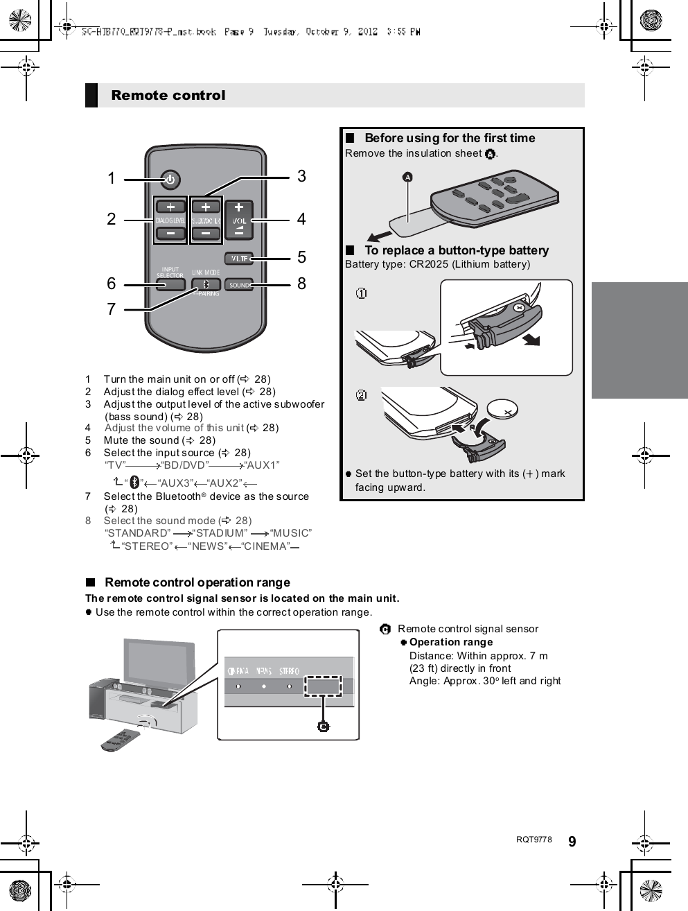
![28 R QT977 8Using this unitPreparationTurn on the active subwoofer.Turn on the TV and/or connected device.Press [ ] to tu rn on the main unit.Sel ect the sou rce.This remote control cannot be used to control the operationsof the connected devices.When is selected as the sourceOn the Bluetooth® device:Select this unit as the output source of the Bluetooth®device and start the playback.Make sure that the Bluetooth® device is already paired withthis unit. ( 2 7)Playback may pause when a different source is selected.When BD/DVD , AUX1 or AUX2is selected as the sourceOn the connected device:Select the TVs input for this unit and start the playb ack onthe connected device.When AUX3 is selected as thesourceOn the connected device:Select the TVs input for the device connected to AUX3terminal and start the playback on the connected device.Adjust the volume and sound effectlevel.To adjust the volume of this unitPress [ VOL ].Volum e range: 1 to 100To adj ust the dial og effect levelThis setting will change the level of the Clear-mode dialog effect. ( 29)1 Press [ DIALOG LEVEL ] to display thecurrent level.2 While the level is displayed:Press [ DIALOG LEVEL ] to adjust thelevel.To adjust the subwoofer level1 Press [ SUBWOOFER ] to display thecurrent level.2 While the level is displayed:Press [ SUBWOOFER ] to adjust thelevel.The level indication pattern is the same as dialog effectlevel.To mute the soundPress [MUTE].While muting, the sound mode indicators blinksimultaneously.To cancel, press the button again or adjust the volume.Muting is canceled if the main unit is turned off.The sound mode indicators b lin k f rom left to rig ht ( ) or from right t o left ( ) wh ile adju sting .The indicators will not blink when it has reached the maximum or minimum.If there is sound coming out of the TVs speakers, reduce the volume of the TV to its minimum.If the main unit is turned off with the volume setting in the greater half (above 50), the main unit will automatically lower thevolume to the middle (50) when the main unit is turned on (Volume limitation).To turn this function off, refer to page 33.Press To select[IN PUTSELECTOR]TVBD/DVDAUX1 AUX3 AUX2[] (Bluetooth®) Indication Effect level4Highest321LowestIf the main unit does not operate as expected or sound is unusual, return the settings to thefactory preset and operate the system again. ( 33)](https://usermanual.wiki/Panasonic-of-North-America/11BT1301.OI-Manual-SC-HTB770-RQT9778-P-121012/User-Guide-1837058-Page-28.png)
![R QT977 8 293D soundThis unit provides a feeling that the sound and the imageare as one.To change the applied effect, refer to Audio outputmodes. ( right)To turn off Dolby Virtual Speaker and the 3D surroundeffects, select STEREO as the audio output mode.(right)To turn off the 3D surround and the Clear-mode dialogeffects, refer to Only using the Dolby Virtual Speakere ffect . ( 3 2)By changing the a udio output mode, i t is possible to enjoythe sou nd that is sui table to the TV program or image fromthe connected device.To select the sound modePress [SOUND].STANDARDSTADIUMMU SICSTEREO NEWS CINEMAThe indicator for the selected sound mode lights.E.g., STANDARDThe setting is maintained until it is changed again.When using the optical digital audio cable, Dolby VirtualSpeaker and the 3D surround effect will be temporarilycanceled if the audio signals sampling frequency is greaterthan 48 kHz.3D sou ndDolby VirtualSpeakerWith this effect you can enjoy asurround sound effect similar to5.1ch.3D surr oundeffectAdding to the Dolby VirtualSpeaker effect, Panasonic h asapplied its own sou nd fieldcontrol ling technology to expandthe sound field fo rwards,backwards, upwards, anddownwards, providing a soundwith depth and fo rce that bettermatches 3D images.Clear-modedialogSports commentary and dialogsfrom TV dramas are heard as if thesound is coming from the TV,giving the feeling that the soundand the image are one.Also, the dialog will stand out fromthe other sounds during n ormalvolume playback and when thevolume is lowered for night timeviewing.e.g., Image of 3D sound fieldAudio output modesSound m odeSTANDARD(Factory preset)Produces a sou nd best suited fordramas and comedy shows.STAD IUMProduces a highly realistic soundfor live broadcasts of sports.MUSICRe-crea tes the sound of musicalinstruments and songs with anexpansive sound.CINEM AProduces a powerful, three-dimenti onal sound unique tomovies.NEWSEnhances the voices of news andsports commentaries for clearerhearing.STEREOYou can play any source in stereo.Dolby Virtu al Speaker and 3Dsurround effects are turned off.](https://usermanual.wiki/Panasonic-of-North-America/11BT1301.OI-Manual-SC-HTB770-RQT9778-P-121012/User-Guide-1837058-Page-29.png)
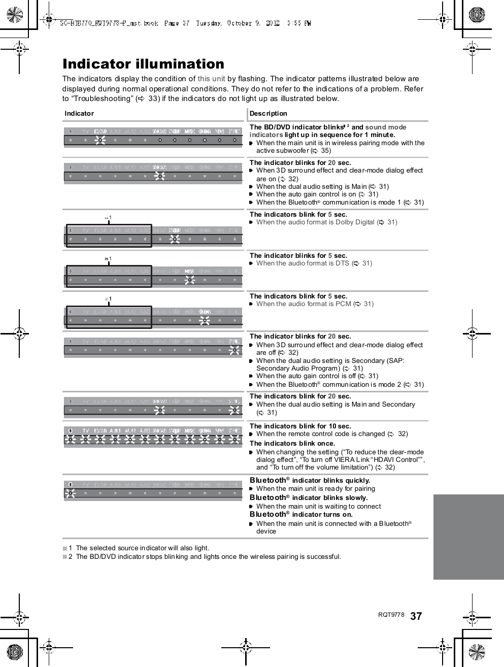
![R QT977 8 31Advanced operationsTo display the current au dio format,Press and hold [SOUND] for more than4 sec.The current audio format is indicated for 5 sec.The audio format status is also indicated for 5 sec if theaudio format on the selected source (TV, Blu-ray Disc/DVD Player, etc.) is changed.Change the dual audio from main to secondary.This setting will only work if the audio outp ut settin g onthe connected TV or player, etc. is set to "Bitstream"and dual audio is available in the audio source.Press and h old [MUTE] for more than4 sec.While the setting is displayed, press[MUTE] to change the setting.The indicator for the selected setting blinks for 20 sec andthen exits the setting mode.The setting is maintained until it is changed again.The same setting is used for all digital audio sources.With this function, you can prevent sudden loud sounds.The output will be reduced automatically when the inputexceeds a certain level.Press and hold [INPUT SELECTOR]on remote controller for more than4sec.While the setting is displayed, press[INPUT SELECTOR] to change thesetting.The indicator for the selected setting blinks for 20 sec andthen exits the setting mode.The setting changes each time [INPUT SELECTOR] ispressed.The setting is maintained until it is changed again.Default se t ting of th is f unc tion is O FF.You can select different modes to suit the type ofconnections which emphasis on connectivity or highquality audio.Make su re that a Bluetoo th® device is already pairedwith this unit. ( 27)Disable the Bluetooth® connection ofthe device.indicator will blink slowly.Press [LINK MODE, ] to display thecurrent mode.While the mode is displayed, press[LINK MODE, ] to select the mode.The setting changes each time [LINK MODE, ] ispressed.The indicator for the selected setting blinks for 10 sec andthen exits the setting mode.The setting is maintained until it is changed again.Audio format indicatorSTADIUM indicator blinks:Dolby Digital is the audio format.MUSIC indicator blinks:DTS is the audio format.CINEMA indicator blinks:PCM or LPCM is the audio format.Changing the dual audioSTANDARD indicator blinks ( ):M a in (Factory preset)STEREO indicator blinks ( ):Secondary(SAP: Secondary Audio Program), : Main and secondaryAuto gain controlSTANDARD indicator blinks:Auto gain control is on.STEREO indicator blinks:Auto gain control is off.(Factory preset)Bluetooth® communicationmodeSTANDARD indicator blinks:MODE1 (Factory preset)Emphasis on connectivitySTEREO indicator blinks:MODE2Emphasis on audio quality](https://usermanual.wiki/Panasonic-of-North-America/11BT1301.OI-Manual-SC-HTB770-RQT9778-P-121012/User-Guide-1837058-Page-31.png)
![32 R QT977 8Depending on your preferen ce, It is possible to turn off the3D surround effect a nd the clear-mode dialog effect.While pressing and holding [SOUND]on the remote control, press andhold [VOL ] on the main unit formore than 4 sec.Whi le th e setti ng is di spl ayed, press[SOUND] to change the setting.The setting changes each time [SOUND] is pressed.The indicator for the selected setting blinks for 20 sec andthen exits the setting mode.This setting will be reset to on when this unit is turned off.When off is selected, the dialog effect level cannot beadjusted.You can turn off dimmer mode and keep the LEDindicators bright.While pressing and holding [INPUTSELECTOR] on the remote control, pressand hold [ VOL] on the main unit to turnoff Dimmer mode.The indicator for the current condition will turn brighter.The setting is maintained until it is changed again.Default setting of this function is on.To turn on dimmer mode, repeat the operation above.After performancing the operation, the indicator for thecurrent condition will be dim.Remote control codeWhen other Panasonic devices respond to this unitsremote control, change the remote control code on themain un it and the remote control.PreparationTurn off all other Panasonic products.Turn on the main unit.Change the remote control code to code 2:1 Aim the remote control at this units remotecontrol sensor.2 Press and hold [MUTE] and [ ] on the remotecontrol for more than 4 sec.All the indicators will blink for 10 sec when the code ofthis unit is changed.The setting is maintained until it is changed again.If this unit does not operate after changing the code, repeatsteps 1 and 2.To change the remote control code to code 1, repeat thesteps above, but replace []with [INPUT SELECTOR].To reduce the clear-mode dialog effectWhen the dialog does not sound natural while the volumeis set low, it is p ossible to reduce the dialog enhancingeffect as follows:While pressing and holding [SOUND] on theremote control, press and hold [ VOL] on themain unit for more than 2 sec.All the indicators will blink once when the clear-mode dialogeffect is reduced.Even if clear-mode dialog effect is reduced, dialog effectlevel is still adjustable.To reset th e setting, re turn to the f ac to ry p res et. ( 3 3)Only using the DolbyVirtual Speaker effectSTANDARD indicator blinks:3D surround effect and clear-modedialog effect is on.STEREO indicator blinks:3D surround effect and clear-modedialog effect is off.Dimmer modeOthers](https://usermanual.wiki/Panasonic-of-North-America/11BT1301.OI-Manual-SC-HTB770-RQT9778-P-121012/User-Guide-1837058-Page-32.png)
![R QT977 8 33To turn off VIERA Link HDAVIControlWhen HDAVI Control compa tible equipment does notwork well with this unit, for example, it is possible to turnoff this function as fo llows:When VIERA Link is turn ed off the ARC function is notavailable. Be sure to connect the optical digital audiocable. ( 24)1 While pressing and holding [MUTE] on theremote control, press and hold [ VOL] on themain unit for more than 4 sec.2 After the setting has changed, turn off all theconnected devices and then turn them onagain.All the indicators will blink once when VIERA Link HDAVIControl is turned off.To re se t the se ttin g, re turn to t he f ac to ry preset. ( right)To turn off the volume limitationIf a state of the lowe red volume disturbs you every timethis unit turns on, for example, it is possible to turn off thisfunction as follows:While pressing and holding [MUTE] on the remotecontrol, press and hold [VOL ] on the main unitfor more than 2 sec.All the indicators will blink once when the volum e limitationis turned off.To re se t the se ttin g, re turn to t he f ac to ry preset. ( right)TroubleshootingBefore re questing service, make the following checks. Ifyou are in doubt about some of the check points, or if thesolutions indicated in the following guide do not solve theproblem, refer to Customer Services Directory (UnitedStates and Puerto Rico) on page 38 if you re side in theU.S.A. o r Puerto Rico, or refer to WARRANTY SERVICEon page 39 if you reside in Canada.No power.Insert the AC power supply cord securely. ( 26)After turning the main unit on, if the indicators blink a ndthe main unit immediately turns off, unplug the ACpower supply cord and consult you r dealer.The remote control does not work properly.The battery is depleted. Replace it with a new one.(9)It is possible that the insulation sheet has not beenremoved. Remove the insulation sheet. ( 9)It may be necessary to set the code of the remotecontrol again after changing the battery of the remotecontrol. ( 32)Use the remote control within the correct operationrange. ( 9)The TV indicator blinks.Remove the AC power supply cord and consult yo urdealer. If there are any oth er indicators blinking, be sureto inform your dealer about the blinking indicators.The main unit is automatically switched tostandby mode.The main unit wi ll automatically switch to standby modewhen no signal is input and no operation is performed forapprox. 30 minutes. ( 26)The main unit is turned off when the TVsspeakers are selected in the speaker control.This is a normal feature when using VIERA Link (HDAVIControl 4 or later). Please read the operatin g instructionsfor the TV for detail s about its power save fea ture. ( 30)To return to the factory preset.While the main unit is on, press [ /I] on the mainunit for more than 4 sec.(All the indicators will blink twice when the mainunit is reset.)If this unit does not operate as expected,returning the settings to the factory presetmay solve the problem.The remote control code will return to whenthe main unit is returned to the factory preset.To change the remote control code, refer topage 32.General operation](https://usermanual.wiki/Panasonic-of-North-America/11BT1301.OI-Manual-SC-HTB770-RQT9778-P-121012/User-Guide-1837058-Page-33.png)
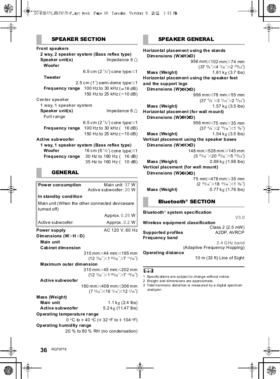
![R QT977 8 35There is no audio.The power of the main unit turns offautomatically.(When the main unit detects a problem, a safety measureis activated and the main unit automatically switches tostandby mode.)There is a problem with the amplifier.Is the volu me extremely high?If so, lower the volume.Isthis unit placed in an extremely hot place ?If so, move this unit to a cooler place and wait a fewmoments and then try to turn it on again.If the problem persists, con firm the TV indicator andBD/DVD indicator blink, turn this unit off, remove the ACpower supply cord and consult your deal er. Please besure to remember the indicators that were blinking andinform th e dealer.No power.Ensure the AC power supply cord of the active subwooferis connected properly.After turning the subwoofer on, it immediatelytu rns off.Unplug the AC power supply cord and consult your dealer.No sound from the subwoofer.Check that the a ctive su bwoofer is turned on.Check that the wireless link indicator lights green.(27)The wireless link indicator lights red.There is no link between this unit and the activesubwoofer.Check that this unit is turned on.Turn the active subwoofer off and then back on.Alternatively, turn the active subwoofer off,discon nect the AC powe r supply cord and thenreconnect it.The active subwoofer an d the main unit may not bepaired corr ectly. Try the following op eration. (Wirelesspairing)Turn on the main unit and active subwoofer.Press [ID SET] on the rear of the active subwoofer.(The WIRELESS LINK indicator will light red andgreen alternately.)While pressing and holding [INPUT SELECTOR] onremote control, press an d hold [VOL ] on the mainunit for more than 4 sec. (The BD/DVD indicator willblink and sound mode indicators light up insequence.)When the wireless pairing is successful, BD/DVDindicator will stop flashing and WIRELESS LINKindicator lights green.Turn the main unit off and on.Consult your dealer if the problem persists.SpecificationsActive SubwooferAMPLIFIER SECTIONRMS ou tput power10 % total harmonic distortionSubwoofer ch120 W per channel (100 Hz, 8 )Fro nt ch (L, R ch)60 W per channel (1 kHz, 6 )Center ch (C ch)60 W per channel (1 kHz, 6 )Total RMS Dolby Digital mode power300 WFTC output pow er1.0 % total harmonic distortionSubwoofer ch60Hzto120Hz40W(8 )Fro nt ch (L, R ch)120 Hz to 20 kHz 25 W (6 )Center ch (C ch)120 Hz to 20 kHz 25 W (6 )Total FTC Dolby Digital m ode power115 WWIRELESS SECTIONWireless moduleFrequency Range 2.4 GHz bandNumber of channels 3TERMINAL SECTIONHDAVI Co ntro lThis unit supports HDAVI Control 5 function.HDMI AV input (BD/DVD, AUX1) 2Inp ut connector Type A (19 pin)HDMI AV output (TV (ARC)) 1Output con nector Type A (19 pin)Digital audio inputOptical digital input (TV, AUX2) 2Sampling frequency32 kHz, 44.1 kHz, 48 kHz88.2 kHz, 96 kHz (only LPCM)Audio form atLPCM, Dolby Digital, DTS](https://usermanual.wiki/Panasonic-of-North-America/11BT1301.OI-Manual-SC-HTB770-RQT9778-P-121012/User-Guide-1837058-Page-35.png)