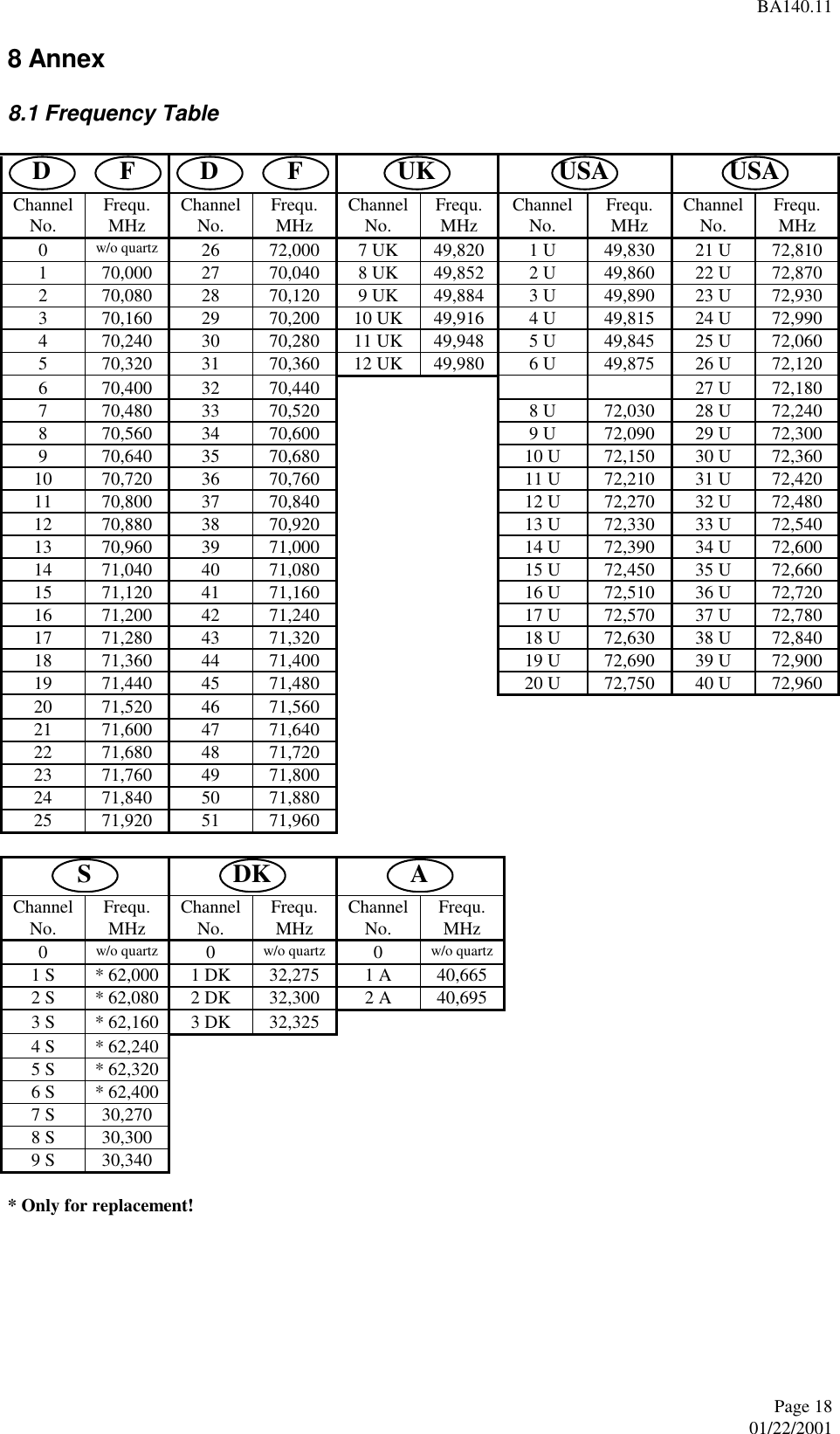
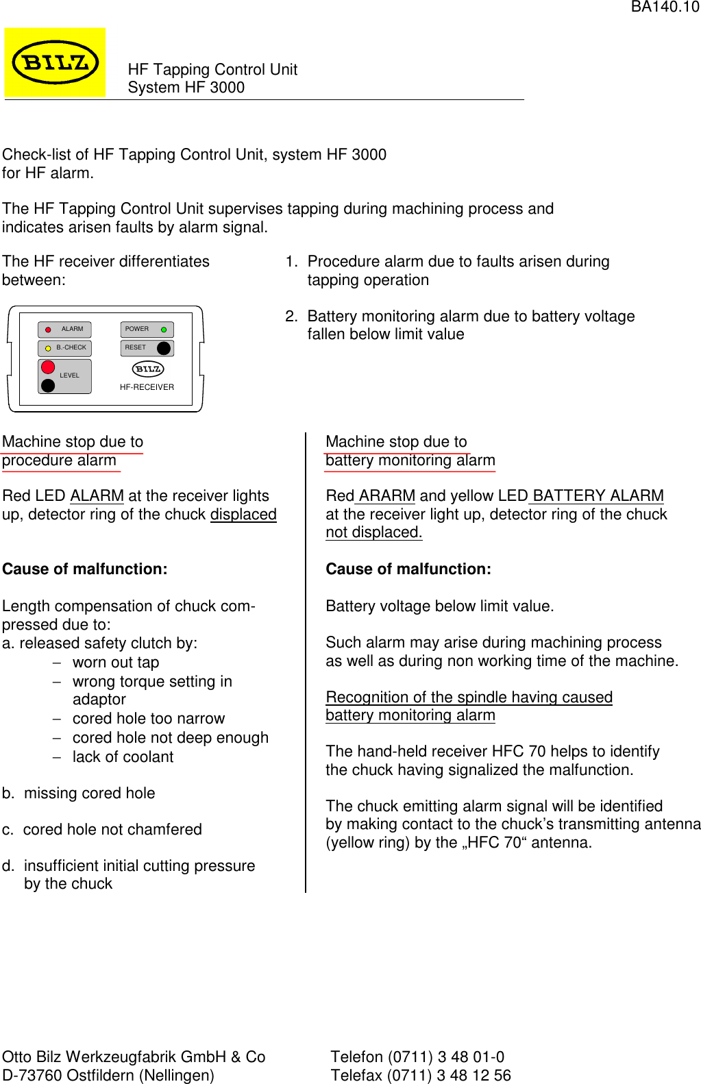
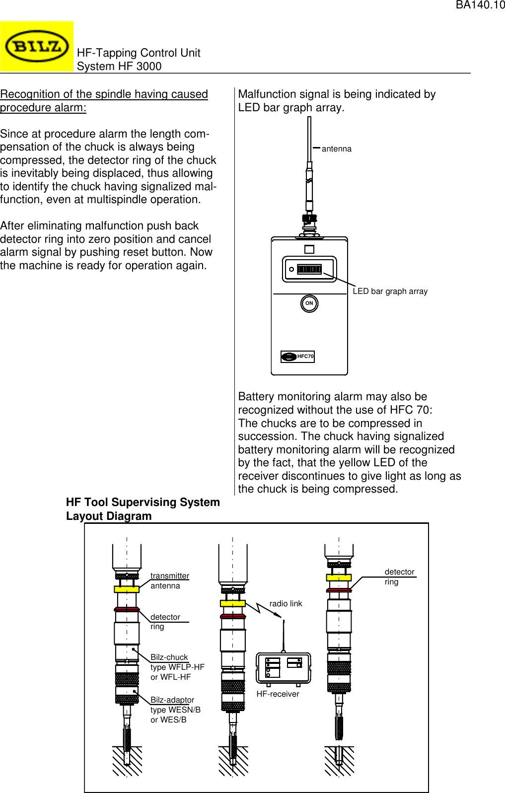
Otto Bilz and HFS3000-49 Wireless Machine Tapping Control System User Manual Manual

Otto Bilz GmbH & Co. Wireless Machine Tapping Control System Manual

Manual

BA140.1 Ik GmbH & CoEln Unternehmen dcr LEITZ METALWORKING TECHNOLOGY GROUPNotes to the FCC authorityto oDerate the equipmentThis device complies with Part 15 of the FCC Rules. Operation is subject to thefollowing two conditions:(l)This device may not cause harmful interference, and(2)thi.s device must accept any interference received, including interference thatmay cause undesired operation.Caution:Changes or modifications not expressly approved by the party responsible forcompliance could void the user’s authority to operate the equipment.This equipment has been tested and found to comply with the limits for a Class Bdigital device, pursuant to Part 15 of the FCC Rules. These limits are designed toprovide reasonable protection against harmful interference in a residential instal-lation. This equipment generates, uses and can radiate radio frequency energyand, if not installed and used in accordance with the instructions, may causeharmful interference to radio communications. However, there is no guaranteethat interference will not occur in a particular installation. If this equipment doescause harmful interference to radio or television reception, which can be deter-mined by turning the equipment off and on, the user is encouraged to try to cor-rect the interference by one or more of the following measures:l Reorient or relocate the receiving antenna.l Increase the separation between the equipment and receiver.lConnect the equipment into an outlet on a circuit different fi-om that to whichthe receiver is connected.lConsult the dealer or an experienced radio/TV technician for help.IIZ Werkzeugfabrik GmbH & Co . Ust-IdNrDE 145355716 . Hand&register Essllngen a N HRA 313 . VogeisangstraRe 8 . 73760 Ostfildern . Postfach 1155 .73747OstflldernTelefon + 49 (0) 711 3 48 01-O - T&fax + 49 (0) 711 3 48 12 56 . C-mall anfo@btlz de . Homepage http iiwww bllr dePersonlich haftende Gesellschafterln Bilz GmbH . Handelsreglster Esslingen a N HRB 1759 . Geschaftsfuhrer Rwner BIIZ Michael Voss,bank Essllngen BLZ 611 400 71 Kto 8 264 780. Baden Wurttemberglsche Bank Aalen, BLZ 600 200 30 Kto 8 960 902 800 . Deutsche Bank Esslingen BLZ 611 700 76 Kto 102 012
BA140.11Ein Unternehmen dcr Lirll~Z METALWORI<ING TECHNOLOGY GROUPHF Wireless Tappim  Control Unit HF 3000OPERATING INSTRUCTION1 Layout Diagram: HF Wireless Tapping Control Unit HF 300032 Introduction3 The HF transmitters3.1 Transmitter “HFS 3100”3.1.1 Operational Modes of HF Transmitter3.1.2 Battery replacement3.2 Transmitter  “HFS 3000”3.2.1 Operational Modes of HF Transmitter3.2.2 Battery replacement3.3 Technical data4 The HF Receivers “HFE 3002” and “HFE 3004”34444444564.1 Operating Elements of HF Receiver and their Functions64.2 Operational and Alarm Modes of HF Receiver84.2.1 Mains operated84.2.2 Standby operational mode84.3 Mains Voltage Setting94.4 Technical Data94.5 Remote Control of Receiver by Programmable Logic Control104.5.1Wiring explanations104.5.2 Status schedule of relaycontacts104.5.3 Wiring Diagram of HF Receiver104.5.4 Realisation of Remote Control Operation114.5.5 Actions at alarm115 The HF Receiver “HFC70” 126 Installation136.1 General Information136.2 Assembly136.2.1 Front mounting of receiver in the switchboard146.2.2 Mounting of receiver with sliding blocks for handle and feet slots147 Maintenance167.1 Quarterly Maintenance167.2 Semi-annual Maintenance178 Annex188.1 Frequency Table188.2 Homologations198.3 Check-list for HF Tapping Alarm Control Unit system 3000, in case of HF alarm20- _._,#IL Werkreugfabrlk GmbH & Co . Ust-IdNrDE 145355716 . Handelsreglster Essilngen a N HRA 313 . VogelsangstraRe 8 . 73760 Ostflldern . Postfach 1155 . 73747OstfbldernTelefor~ + 49 (0)7113 48 01-O . T&fax + 49 (0) 711 3 48 12 56 . E-mall mfo@bllz de * Homepagehttp iiwww bllz dePersonllch haftende Gesellschafterin BIIZ GmbH . Handelsreglster Essllngen a N HRB 1759 . Geschaftsfuhrer Remer Bllr, Michael Vossrbank Essllngen, BLZ 611 400 71 Kto 8 264 780 . Baden Wurttemberglsche Bank Aalen, BLZ 600 200 30, Kto 8 960 902 800 .Deutsche Bank Esslmgen BLZ 611 700 76 Kto 102 012
BA140.11Page 301/22/20011 Layout Diagram: HF Wireless Tapping Control Unit HF 30002 IntroductionHF Tapping Control Unit (HF = High Frequency)When tapping on transfer lines, special purpose machines and machining centers, damage of the tap cannot al-ways be prevented. Occasionally, the threads are not tapped to full depth or are missing at all. Such faults remainoften undetected until assembling of the parts. This causes high remachining costs and means sometimes even therejection of the component. In combination with the BILZ WFL, WFLK or WFLP Quick Change TappingChucks and Adaptors with safety clutch, the HF unit controls the thread depth, identifies possible tap breakageduring tapping operation and prevents such malfunctions.max. 3 mHFA 0receiving antennaHFA 2adaptor withsafety clutchtapping unittransmitterantennachuck withlength compensationreceiving antenna HFA 2HF-RECEIVERALARM POWERBILZB.-CHECKLEVELRESETPOWERALARMHF-receiverHFE 3002: 2 antenna inputsHFE 3004: 4 antenna inputs machine controlcoaxial cablex = length in meter      (max. 25 m)HFK 2.xmultiple cable to machine control(optional length)HFK 0.xHFK 0.xreceiving antennaHFA 0
BA140.11Page 401/22/20013 The HF transmitters3.1 Transmitter ”HFS 3100”3.1.1 Operational Modes of HF TransmitterCollision alarm Battery monitoring alarmAlarm triggering:Chuck is compressed in the clockwise direction orextended in the anticlockwise directionAlarm triggering:Battery voltage drops below 3.0 V.Reaction:HF signal in 1 sec. rhythm Reaction:HF signal in .5 sec. rhythm.End of alarm:Collision alarm is cancelled 5 sec. after chuck release.Transmitters of extended transmittal time are availableon requestEnd of alarm:Battery monitoring alarm can be cancelled onlyby removing  the empty battery.As long as no alarm is being triggered the HF transmitter is in inoperative position and requires max.20 µA of energy.3.1.2 Battery replacementAs soon as a battery monitoring alarm is being triggered, the battery is to be replaced immediately.• Remove from spindle the chuck having triggered battery monitoring alarm (for identification see 4.2.1), dry itup and unscrew plug screw from shank.• Remove empty battery and replace it by a new one.Attention: Insert battery with negative pole (-) towards open end of shank.For replacement purposes use only lithium-thionyl-chloride batteries, size ½AA(preferably Sonnenschein SL-750/S).• Screw in again shank plug screw.  3.2 Transmitter ”HFS 3000” 3.2.1 Operational Modes of HF Transmitter  Collision alarm  Battery monitoring alarm Alarm triggering:Chuck is being compressed  Alarm triggeringBattery voltage drops below 3,1 V. Reaction:Permanent HF signal  Reaction:Permanent HF signal End of alarm:Alarm is being cancelled only after releasing the chuck  End of alarm:Battery monitoring alarm can be cancelled only byremoving the empty battery. As long as no alarm is being triggered the HF transmitter is in inoperative position and requires max. 20 µA ofenergy. 3.2.2 Battery replacement As soon as a battery monitoring alarm is being triggered the battery is to be replaced immediately.• Remove from spindle the chuck having triggered battery monitoring alarm (for identification see 4.2.1), dry itup and unscrew plug screw from shank.• Remove batteries and test voltage using battery tester: minimum 3.0 V.• Replace empty batteries by new ones.• Remove transmitter from shank by pulling it downward; do not lose spring of switch pin .• Visual inspection of transmitter:1. for humidity and corrosion2. for integrity of contact bow.
BA140.11Page 501/22/2001• Putting back the transmitter into the chuck:1. Place the spring on the switching pin and push the transmitter back into the shank hole from the bottomtowards the top.2. Insert batteries with the positive pole to the open end of the shank. 3 mercuryoxide batteries are neededfor replacement purposes (according to IEC NR07, NR44 or ANSI N15 resp. USASI M15)  e.g.:Varta V675HP, Mallory M P 675 H, Daimon/Berec MP675H, Ucar EP 675E, FDH 675E.Zinc-air batteries must not be used.All of the 3 batteries are to be replaced at the same time.3. Replace O-ring on the screwplug each time the plug had been unscrewed. Screw plug is to be tightenedwith 5 to 6 Nm.  3.3 Technical data   General Country  FRG  U.K.  USA  USA  Sweden   frequency range  70.00-72.00  49.82-49.98  49.83-49.89  72.00-72.99  30.27-30.34  MHz channel spacing  80  16  15  30  30/40  kHz  transmitting range (distance chuck - antenna) abt.  3 m HF-output  < 1  nW permissible ambient temperature  0 - 80  °C  HFS 3100 Power source: lithium thionyl chloride battery  3.6  V Battery capacity  850  mAh  HFS 3000 Power source: 3 mercury batteries 1.4 V each  4.2  V Battery capacity  240  mAh  springchuckdetector ringtransmitting antenna (yellow)adjusting nuttransmitterNo. of transmitting channelplastic bushingspringbatteriesO-ringplug screw
BA140.11Page 601/22/2001 4 The HF Receivers ”HFE 3002” and ”HFE 3004” 4.1 Operating Elements of HF Receiver and their Functions  a) Front panel of the unit   Element:   Function: S1  ”RESET” button  A signal emitted by a chuck will be memorizedby the receiver. Pushing ”RESET” button willclear the receiver.  D12  Yellow ”B.-CHECK” indicator  Lights up only as long as a signal emitted byone of the chucks on this receiver’s channel isbeing received.  D13  Red ”ALARM” indicator  Informs that a signal emitted by one or severalchucks on this receiver’s channel has been and/oris being received.  D14  Green mains indicator  Lights up when power is switched on.  BU1 (-), BU2 (+)  Level output  The strength of the HF signal received (level) canbe measured by voltmeter. The level depends onantenna’s positioning (see 6.2).  b) Rear panel of the unit    ALARMB.-CHECK    LEVELRESETPOWERBILZHF-RECEIVERD12 D13 D14 S1BU1 BU2X6 X1X2 X3 X4 X5
BA140.11Page 701/22/2001  Element:   Function X1  Multiple connector  Ten pin plug for Harting socket HAN 10 A forremote control of the receiver, see below and 4.5. The socket is to be inserted all the time. If remotecontrol isn’t needed, please install bridge (part of oursupply).  X2, X3, X4, X5  Antenna inputs  Coaxial socket type N with an impedance of 50 Ohm. The receiver ”HFE 3002” is being equipped withthe two antenna inputs X2 and X3 only.  X6  Mains connection  Mains connection of abt. 1.8 m incl. line plug. Tochange mains voltage shift bridges on printed boardinside the receiver.  Assignment of multiple connector X1:    Element:   Function X1 comprises:    REL1  Normally closed contact  ”B.-CHECK” contact, open when signal from tool isbeing received.  REL2  Normally closed contact  ”ALARM” contact, open when signal from one orseveral chucks on this receiver’s channel has beenand/or is being received.  REL4  Operating contact  Power contact, closed when power supply is switchedon.  9101234562REL23REL41REL1R1.1Remote control connectionmultiple connector X1To machine controlmultiple socket (type HAN 10A)B.-CHECKALARMPOWER ON4COM5678RESETHFRELGND78910R2.1
BA140.11Page 801/22/2001 4.2 Operational and Alarm Modes of HF Receiver 4.2.1 Mains operated Collision alarm  Battery monitoring alarm Yellow ”B.-CHECK” indicator and ”REL1” contact: Transmitter HFS 3000  Transmitter HFS 3100  Transmitter HFS 3000  Transmitter HFS 3100 As long as an alarm signalis being received,”B.-CHECK” indicatorlights up.”REL1” contact: open. As long as an alarm signalis being received,”B.-CHECK” indicator isflashing in 1 sec. rhythm.”REL1” contact opens andcloses in the same rhythm. As long as an alarm signalis being received,”B.-CHECK” indicatorlights up.”REL1” contact: open.. As long as an alarm signalis being received,”B.-CHECK” indicator isflashing in .5 sec. rhythm.”REL1” contact opens andcloses in the same rhythm. Red ”ALARM” indicator and ”REL2” contact: As soon as the HF receiver has identified an alarm signal, the ”ALARM” indicator lights up and the ”REL2” con-tact opens.This situation will remain unchanged even after alarm signal ends, until the receiver will be reset by pushingRESET button of its front panel or by opening the bridge between pins 8 and 10 of the multiple plug X1.  Recognition of faulty thread spindle in case of collision alarm: All HF transmitters in the chucks of one multi-spindle tapping station can operate on the same frequency, i.e. onthe same channel. To recognize the spindle of the faulty thread, the chuck shanks are equipped with detectorrings. When the length compensation of a chuck gets compressed, the detector ring will be moved upwards andthus identifies the spindle of the faulty thread. After correction, the detector ring is to be pushed back by handinto zero position. Minimum compression length to get a signal response from the chucks is 1 mm (.04”).  Recognition of the spindle with battery monitoring alarm: In case of alarm, all chucks are to be released first. If luminous diode ”B.-CHECK” continues lighting or flashing(HFS 3100): A battery monitoring alarm has occurred. The individual chucks of the different spindles are to becompressed now in succession. When compressing the chuck giving battery monitoring alarm, luminous diode”B.-CHECK” will discontinue to give light. When compressing any other chuck, the luminous diode”B:_CHECK” will continue to light up resp. to flash. The chuck giving battery monitoring alarm can be identified much easier by using the HF receiver”HFC 70”. After recognition of the chuck having caused battery monitoring alarm and after battery replacement, the detectorrings are to be pushed back into zero position. 4.2.2 Standby operational mode During intermissions (mains cut off) the receiver switches on periodically for short moments, to check if one ofthe chucks is emitting battery monitoring alarm and, if any, memorizes it. During stand-by neither the indicatordiodes of the front panel nor the remote control relays are being activated. A fully loaded buffer batteryallows to maintain stand-by for abt. 3 weeks. After switching on again electricity supply system, the alarm indi-cating diodes of the receiver’s front panel are being switched on, too, and the remote control relays are beingactivated as well.  Recognition of the chuck having caused battery monitoring alarm, after switching on mains supply: Weak battery  Empty battery• Red ”ALARM” indicator lights up.• Yellow ”B.-CHECK” indicator lights up orflashes in .5 sec. rhythm (HFS 3100).• Red ”ALARM” indicator lights up.• Yellow ”B.-CHECK” indicator does not light up. see chapter 4.2.1  Check all chucks by compressing one after another.• Active battery: ”B.-CHECK” lights up or flashes in1 sec. rhythm (HFS 3100).• Empty battery: ”B.-CHECK” doesn’t light up.
BA140.11Page 901/22/2001 4.3 Mains Voltage Setting   SI  Fuse socket  To change mains fuse, remove cover, replace fuse(63 mA, slow), put back cover.  SK1, SK2  Screw clips  To connect mains supply.   4.4 Technical Data Mains voltage   115 V +/- 10 % or 230 V +/- 10  % Mains frequency   50 - 60  Hz Fuse  (slow)  63  mA Power consumption   6.9  VA Battery voltage   12  V Battery capacity   280  mAh Permissible ambient temperature   0 - 65  °C Recommended antennae  HFA 0 and HFA 2   Relay contact rating  230 V / 2  A Sensitivity  - 90  dBm Adjacent channel suppression (40 kHz separation)  > 40  dB Number of channels per receiver  1  Number of antenna connections per receiver    HFE 3002  2  HFE 3004  4  Antenna impedance  50  Ohm Degree of case protection   IP54  Dimensions  Width  * Height  * Length    160  * 98  * 340  mm  6.3  * 3.9  * 13.4  inch  Weight  2.4  kg   5.3  pound  ATTENTION!!!Disconnect mains supply before opening equipment!!! SK1SK2 SK2SK1LNwire bridgeLN230 V: 115 V:wire bridges
BA140.11Page 1001/22/2001 4.5 Remote Control of Receiver by Programmable Logic Control 4.5.1 Wiring explanations R1, R2  Relay R1.1  Normally closed contact of relay R1, controlled by one of the PLC outputs R2.1  Main contact of relay R2, controlled by one of the PLC outputs E1, E2, E3  Inputs of PLC A1, A2, A3  Outputs of PLC VS  Voltage supply, up to 230 V GND  Ground wire of voltage supply REL1, REL2  Normally closed contacts of the relays inside the receiver REL4  Main contact of REL4 relay inside the receiver 4.5.2 Status schedule of relaycontacts Contact  REL1 B.-CHECK  REL2 ALARM  REL4 POWER ON No power supply  closed  closed  open Power supply switched on and:     no signal received so far  closed  closed  closed signal is just being received  open  open  closed signal was received  closed  open  closed reset when just no signal is being received  closed  closed  closed The receiver is memorizing the reception of a signal until reset by front panel button or by reset input onremote control connection, respectively. 4.5.3 Wiring Diagram of HF Receiver COMMANDEPROGRAMMABLE(SPS)programable logic control(PLC)84132REL1REL4REL2R1.1POSTE-RÉCEPTEUR HFHF-ReceiverE1E2E3 }ENTRÉES SPSPLC-inputsVS SOURCE DE TENSIONVoltage sourceGND Masse / GroundA1A2SORTIES SPSPLC-outputs10PONT OU R1.1wire bridge or R1.1SCHÉMA DE CÂBLAGE POUR TÉLÉCOMMANDEWiring diagram for remote operationB.-CHECKPOWER ONALARMCOMRESETGND9HFREL A3 R2.1
BA140.11Page 1101/22/2001 4.5.4 Realisation of Remote Control Operation• Wire receiver according to wiring diagram of chapter 4.5.3.• PLC supervises inputs E1, E2, E3.• When not operated (mains supply connected), inputs E1, E2, E3 are connected to VS. Input  Function  Source of signal at receiver E1  B.-CHECK  Output 1 E2  Mains  Output 3 E3  ALARM  Output 2  Output  Function  Action A1, A2  Reset of receiver  Bridge between receiver’s inputs8 and 10 is being opened A2, A3  HF reception suppressed  Bridge between receiver’s inputs9 and 10 is being closed After a malfunction signal and the necessary steps, the machine control cancels the signal. For that purpose PLCwill activate the contact R1.1 for a short moment (> .1 sec). 4.5.5 Actions at alarm Program step KError signal atinput E3?Retract the unit,release all chucksAlarm ofcollision detectionSight ring is shiftedCheck tool and workpiecereplace if necessaryResetHFE 3002 / HFE 3004Shift sight ringsto zero positionyesnoBatterymonitoringalarmyes Compress each toolin successionyesReplace batteryof this toolProgram step K+1nonoError signal atinput E1?Error signal atinput E1?ResetHFE 3002 / HFE 3004Shift sight ringsto zero positionDuring this actions at alarm, the bridgebetween pins 9 and 10 of the HARTINGsocket must be open.
BA140.11Page 1201/22/2001 5 The HF Receiver ”HFC 70” The use of the HF receiver ”HFC 70” is of help to easily identify a chuck having caused battery monitoringalarm. Such chuck can be identified by making contact to the transmitting antenna (yellow ring) of the chuck by the”HFC 70” antenna.  Operating elements of the hand-held receiver• ON button:Hand held receiver is switched on as long as ON button is being pushed.• Indication of signal level (by LED):The level of the signal received by the stub antenna is being shown by LED row. A distinct deflection will beseen only after the antenna bar has nearly touched the antenna ring on the chuck.• Battery check:A red LED in the left corner of the LED row is determined to show operating readiness:fully charged battery:when pushing ON button: LED lights up for a short momentweak battery:when pushing ON button: LED doesn’t light up  The battery is of standard 9 V bloc type.   ONHFC70antennaON buttonLED indicationbatterycheck
BA140.11Page 1301/22/2001 6 Installation 6.1 General Information The HF receiver is protected against interference pulses. Normally adjacent electrical motors, transformers, con-trols, radios etc. will not cause alarm signals. On the operating frequency, interference signals must not exceedthe maximum level of -93 dBm. The field strength of the HF signal transmitted by the chucks stays below the permitted upper limit, and thusinterference with other radio services and other electronic equipment are prevented. We recommend that BILZ HF Equipment on adjacent machines is operated on different channels to avoidmutual interference.  6.2 Assembly  HF Quick Change Tapping Chucks The insertion of HF Quick Change Tapping Chucks into the spindle is simple and follows the same principle asstandard chucks. However, avoid damaging the yellow isolation of the antenna ring which neither must be com-pletely screened by metallic items.  Receiver antennae 2 (HFE 3002) or 4 (HFE 3004), respectively, antennae can be connected to the HF receivers. The positioning ofthe antennae should be as close as possible to the chucks, however far enough away from metallic parts (mini-mum distance 30 cm), to avoid weakening of the HF reception field. The ideal length of the antenna bar is one quarter of the wavelength, as a rule the antenna is abt. 1.1 m long (HFA0). However, if lack of space prevents the use of such antenna, a shorter one (HFA 2) can be used. The antenna cable (RG58U) should be as short as possible; the maximum length between each antenna and thereceiver is 25 m. Please handle the antenna cable with care, do not pull nor bend it!  Level output on the front panel of HF receiver To make installation easier and to evaluate the strength of a signal received, the receivers are equipped with alevel output which can be connected to standard voltmeters. Digital voltmeters must not be used, as they cannot react quickly enough to the transmitter’s pulsedsignals.To evaluate the level of a signal received by a certain antenna, only this one is to be connected to the re-ceiver. All other antennae are to be disconnected from the receiver so far. The voltage at the level output is increasing depending on the level of the signal received.  The following standard values should be considered for new transmitter batteries:• Voltage < 1 V: weak signal received, improve antenna positioning.• Voltage > 2 V: good signal received.Additional AntennaeIf, despite optimal antenna positioning, the signal level remains too low (metal parts and/or coolant may affecttransmission fields), additional antenna rings combined with rods can improve the radiation of signals from thechuck group. These are special items to be designed for each individual case. For any further advice we will begladly at your disposal.
BA140.11Page 1401/22/20016.2.1 Front mounting of receiver in the switchboard6.2.2 Mounting of receiver with sliding blocks for handle and feet slots1sliding block for handle slot 2sliding block for feet slotsThe sliding blocks (extruded aluminium, alodine) provide an optional means of attachment for the receiver case.The blocks are inserted in the lateral slots of the case or in place of the feet.Line drawing of the attachment points     sliding block for handle slot     sliding block for feet slotsNotes: -all distances in mm-centre distance between the two feet slots: 83.4 mm.HF-RECEIVERRESETPOWERLEVELB.-CHECKALARM2678615796bracket setGT/33-650Ident-Nr. 43927844consisting of:one bracket foreach sideretaining screws M4not included in our supply179151R768814,5detail of front panelinsertion depth of receiver,including plug abt. 310 mmall dimensions in mm!
BA140.11Page 1501/22/20016.2.3 BILZ Antennae∅∅∅∅ 12SW 14∅∅∅∅ 5SW 17serrated lock washerantenna base,not includedin our supplycable,5 meterswasher∅∅∅∅5λλλλ /4to coaxial socketof receiverSW 17max. 5HFA 0all dimensions in mm∅∅∅∅ 5cable,5 meters∅∅∅∅17∅∅∅∅ 13washerantenna base,not includedin our supplyto coaxial socketof receiverca. 283max. 3HFA 2all dimensions in mm
BA140.11Page 1601/22/20017 Maintenance7.1 Quarterly Maintenance1. Sight inspection of antenna and its accessories:a. damages, dirt, moistureb. screwed connections of the antenna cable and loose plug connections of the remote control indicator.Protocol:Date: Name:1st yearly quarter2nd yearly quarter.3rd yearly quarter4th yearly quarter2. Quick change adaptors type WESNDismantle adaptors’ safety clutches, clean everything and refill with grease Molykote Pate G, readjusttorque according to operating instructions and table BA 102. For cold-forming of threads increase torque val-ues by 50 % to the values shown in tapping torque tables.Protocol:Date: Name:1st yearly quarter2nd yearly quarter3rd yearly quarter4th yearly quarter
BA140.11Page 1701/22/20017.2 Semi-annual MaintenanceHFS 3100:Check of transmitter batteries: All chucks are to be compressed in turnFully charged battery Weak battery Empty batteryChuck compressed:Yellow ”B.-CHECK” LED flashesin 1 sec. rhythm.Chuck compressed:Yellow ”B.-CHECK” LED flashesin 1 sec. rhythm.Chuck compressed:Yellow ”B.-CHECK” LED doesn’tlight up.Chuck released:Yellow ”B.-CHECK” LED flashesin 1 sec. rhythm till follow-up timeof transmitter has run out, afterwhich indication ends.Chuck released:Yellow ”B.-CHECK” LED flashesin 1 sec. rhythm till follow-up timeof transmitter has run out, afterwhich it flashes in .5 sec. rhythm(battery monitoring alarm).Chuck released:Yellow ”B.-CHECK” LED doesn’tlight up.Remedial actions:No action required! Remedial actions:Replace battery! Remedial actions:Replace battery!HFS 3000: Remove battery block as per 3.2.2 and test voltage by battery tester: minimum 3.0 V.Protocol:Date: Name:1st half of the year2nd half of the year
BA140.11Page 1801/22/20018 Annex8.1 Frequency TableD    F D     FUK USA USAChannelNo. Frequ.MHz ChannelNo. Frequ.MHz ChannelNo. Frequ.MHz ChannelNo. Frequ.MHz ChannelNo. Frequ.MHz0w/o quartz 26 72,000 7 UK 49,820 1 U 49,830 21 U 72,8101 70,000 27 70,040 8 UK 49,852 2 U 49,860 22 U 72,8702 70,080 28 70,120 9 UK 49,884 3 U 49,890 23 U 72,9303 70,160 29 70,200 10 UK 49,916 4 U 49,815 24 U 72,9904 70,240 30 70,280 11 UK 49,948 5 U 49,845 25 U 72,0605 70,320 31 70,360 12 UK 49,980 6 U 49,875 26 U 72,1206 70,400 32 70,440 27 U 72,1807 70,480 33 70,520 8 U 72,030 28 U 72,2408 70,560 34 70,600 9 U 72,090 29 U 72,3009 70,640 35 70,680 10 U 72,150 30 U 72,36010 70,720 36 70,760 11 U 72,210 31 U 72,42011 70,800 37 70,840 12 U 72,270 32 U 72,48012 70,880 38 70,920 13 U 72,330 33 U 72,54013 70,960 39 71,000 14 U 72,390 34 U 72,60014 71,040 40 71,080 15 U 72,450 35 U 72,66015 71,120 41 71,160 16 U 72,510 36 U 72,72016 71,200 42 71,240 17 U 72,570 37 U 72,78017 71,280 43 71,320 18 U 72,630 38 U 72,84018 71,360 44 71,400 19 U 72,690 39 U 72,90019 71,440 45 71,480 20 U 72,750 40 U 72,96020 71,520 46 71,56021 71,600 47 71,64022 71,680 48 71,72023 71,760 49 71,80024 71,840 50 71,88025 71,920 51 71,960SDK AChannelNo. Frequ.MHz ChannelNo. Frequ.MHz ChannelNo. Frequ.MHz0w/o quartz 0w/o quartz 0w/o quartz1 S * 62,000 1 DK 32,275 1 A 40,6652 S * 62,080 2 DK 32,300 2 A 40,6953 S * 62,160 3 DK 32,3254 S * 62,2405 S * 62,3206 S * 62,4007 S 30,2708 S 30,3009 S 30,340* Only for replacement!
For EC-Type Examination see separate file8.2   Homologations
BA140.10Otto Bilz Werkzeugfabrik GmbH & Co Telefon (0711) 3 48 01-0D-73760 Ostfildern (Nellingen) Telefax (0711) 3 48 12 56HF Tapping Control UnitSystem HF 3000Check-list of HF Tapping Control Unit, system HF 3000for HF alarm.The HF Tapping Control Unit supervises tapping during machining process andindicates arisen faults by alarm signal.The HF receiver differentiatesbetween: 1.  Procedure alarm due to faults arisen during     tapping operation2.  Battery monitoring alarm due to battery voltage     fallen below limit valueMachine stop due toprocedure alarmRed LED ALARM at the receiver lightsup, detector ring of the chuck displacedCause of malfunction:Length compensation of chuck com-pressed due to:a. released safety clutch by:−  worn out tap−  wrong torque setting inadaptor−  cored hole too narrow−  cored hole not deep enough−  lack of coolantb.  missing cored holec.  cored hole not chamferedd.  insufficient initial cutting pressure     by the chuckMachine stop due tobattery monitoring alarmRed ARARM and yellow LED BATTERY ALARMat the receiver light up, detector ring of the chucknot displaced.Cause of malfunction:Battery voltage below limit value.Such alarm may arise during machining processas well as during non working time of the machine.Recognition of the spindle having causedbattery monitoring alarmThe hand-held receiver HFC 70 helps to identifythe chuck having signalized the malfunction.The chuck emitting alarm signal will be identifiedby making contact to the chuck’s transmitting antenna(yellow ring) by the „HFC 70“ antenna.   ALARMB.-CHECK    LEVELRESETPOWERHF-RECEIVER
BA140.10HF-Tapping Control UnitSystem HF 3000Recognition of the spindle having causedprocedure alarm:Since at procedure alarm the length com-pensation of the chuck is always beingcompressed, the detector ring of the chuckis inevitably being displaced, thus allowingto identify the chuck having signalized mal-function, even at multispindle operation.After eliminating malfunction push backdetector ring into zero position and cancelalarm signal by pushing reset button. Nowthe machine is ready for operation again.Malfunction signal is being indicated byLED bar graph array.ONHFC70antennaLED bar graph arrayBattery monitoring alarm may also berecognized without the use of HFC 70:The chucks are to be compressed insuccession. The chuck having signalizedbattery monitoring alarm will be recognizedby the fact, that the yellow LED of thereceiver discontinues to give light as long asthe chuck is being compressed.HF Tool Supervising SystemLayout Diagramtransmitter antennadetectorringBilz-chucktype WFLP-HFor WFL-HFBilz-adaptortype WESN/Bor WES/BHF-receiverradio linkdetectorring

Navigation menu