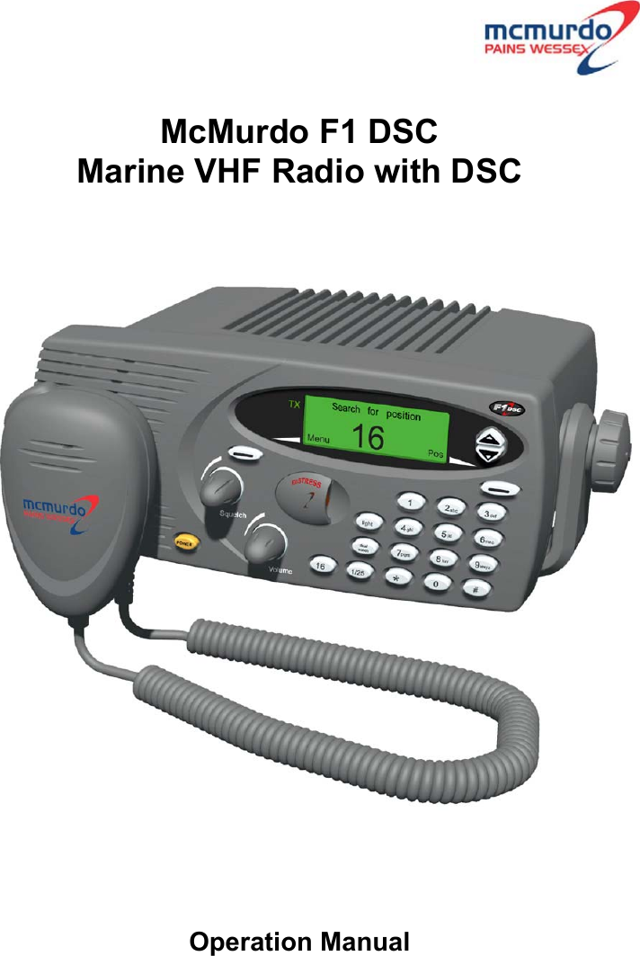
Orolia F1DSC VHF Marine radiotelephone inc.class 'D' DSC User Manual F1 DSC Radio Operator Manual
Orolia Ltd VHF Marine radiotelephone inc.class 'D' DSC F1 DSC Radio Operator Manual
Orolia >
Contents
- 1. Installation
- 2. Operator
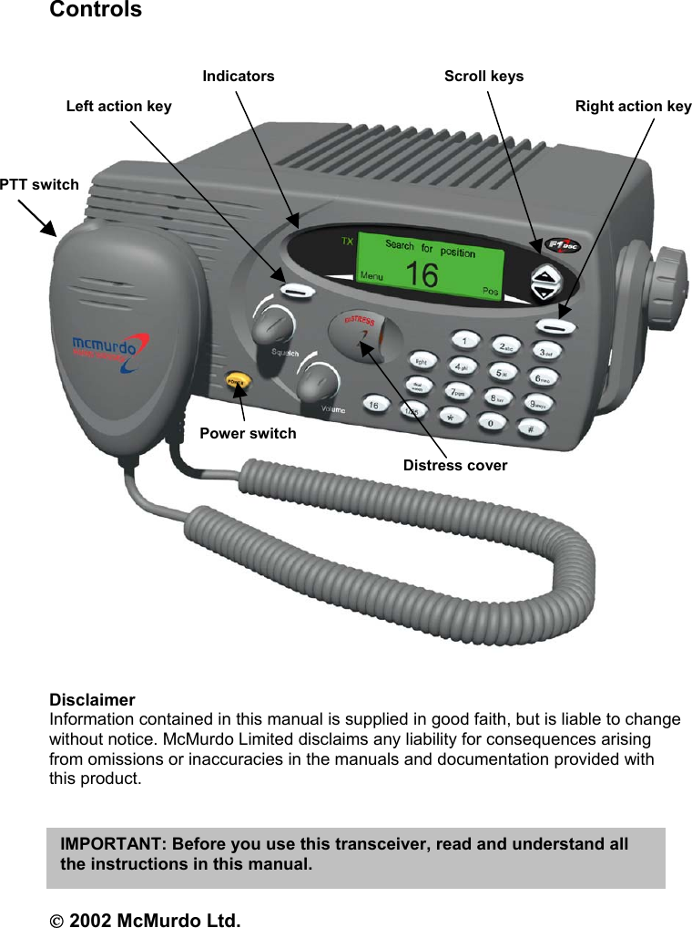
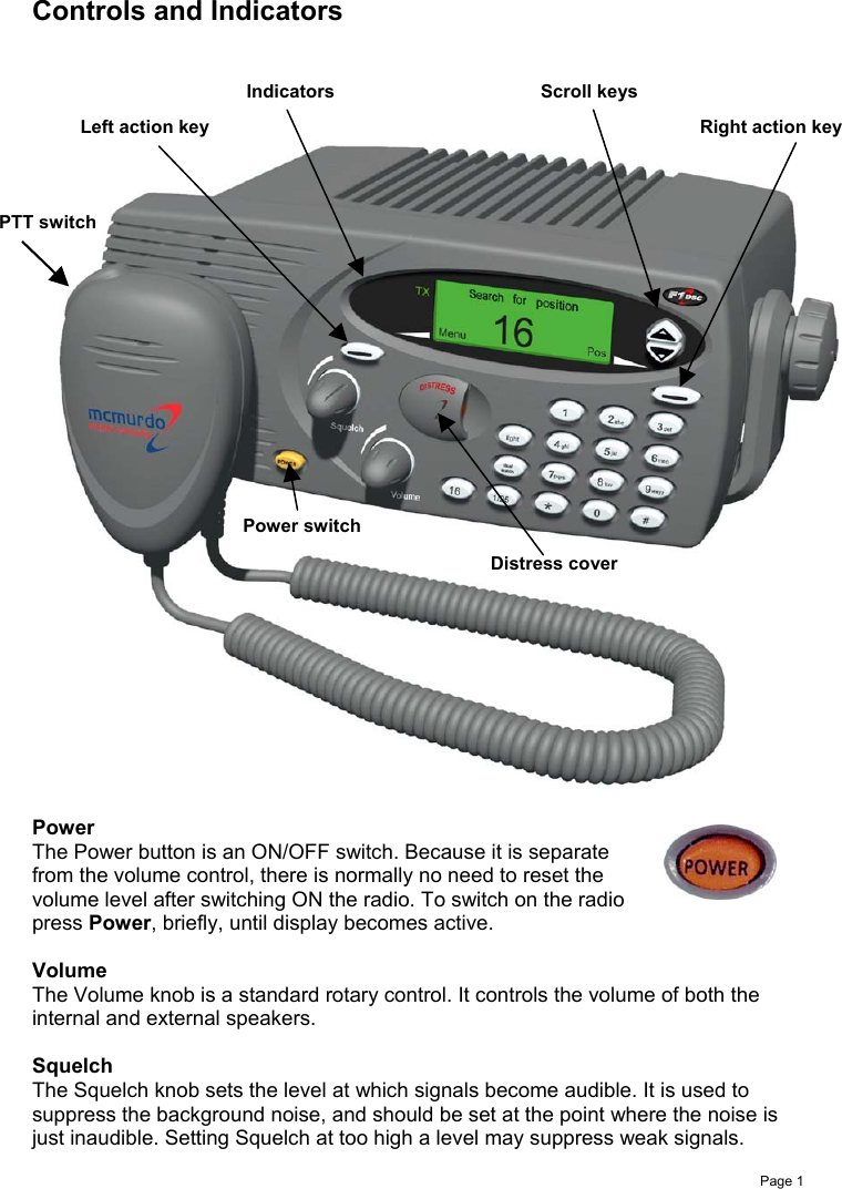
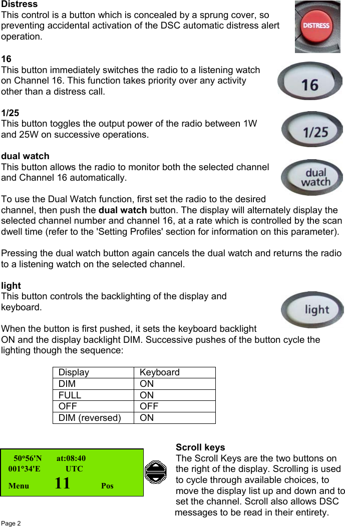
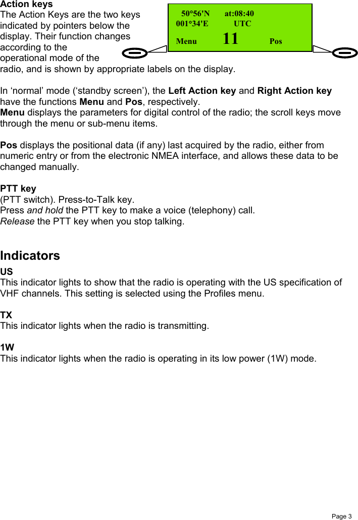
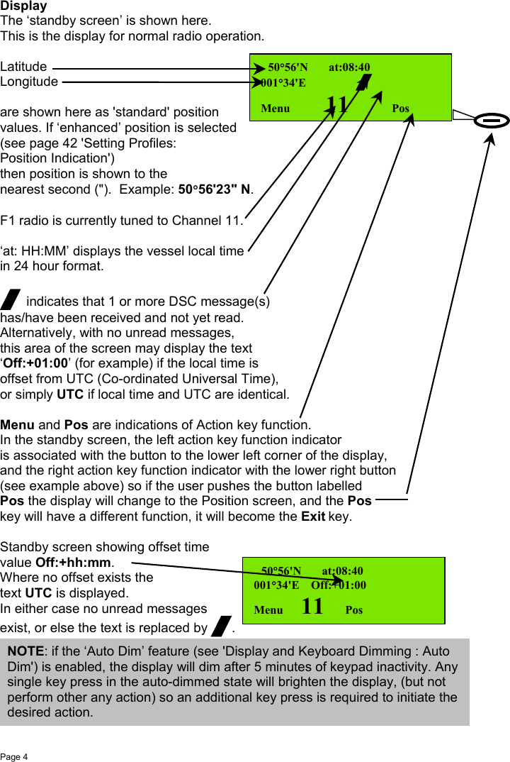
Operator
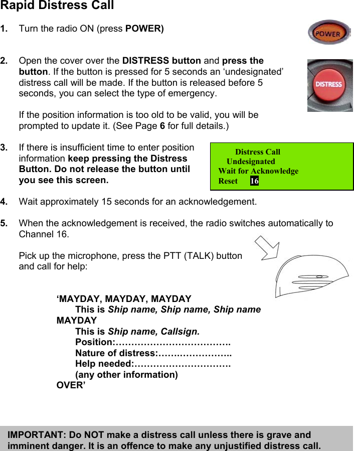
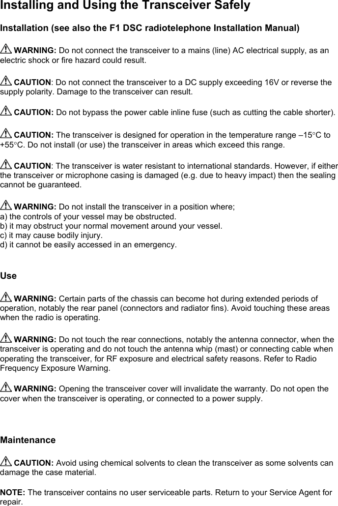
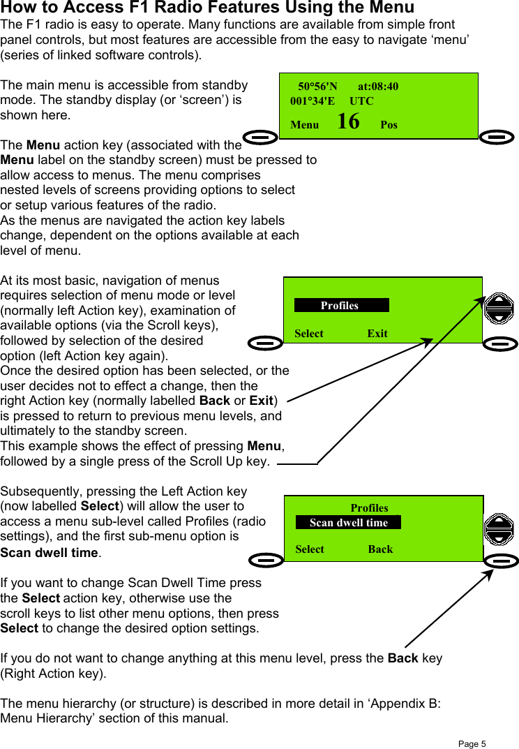
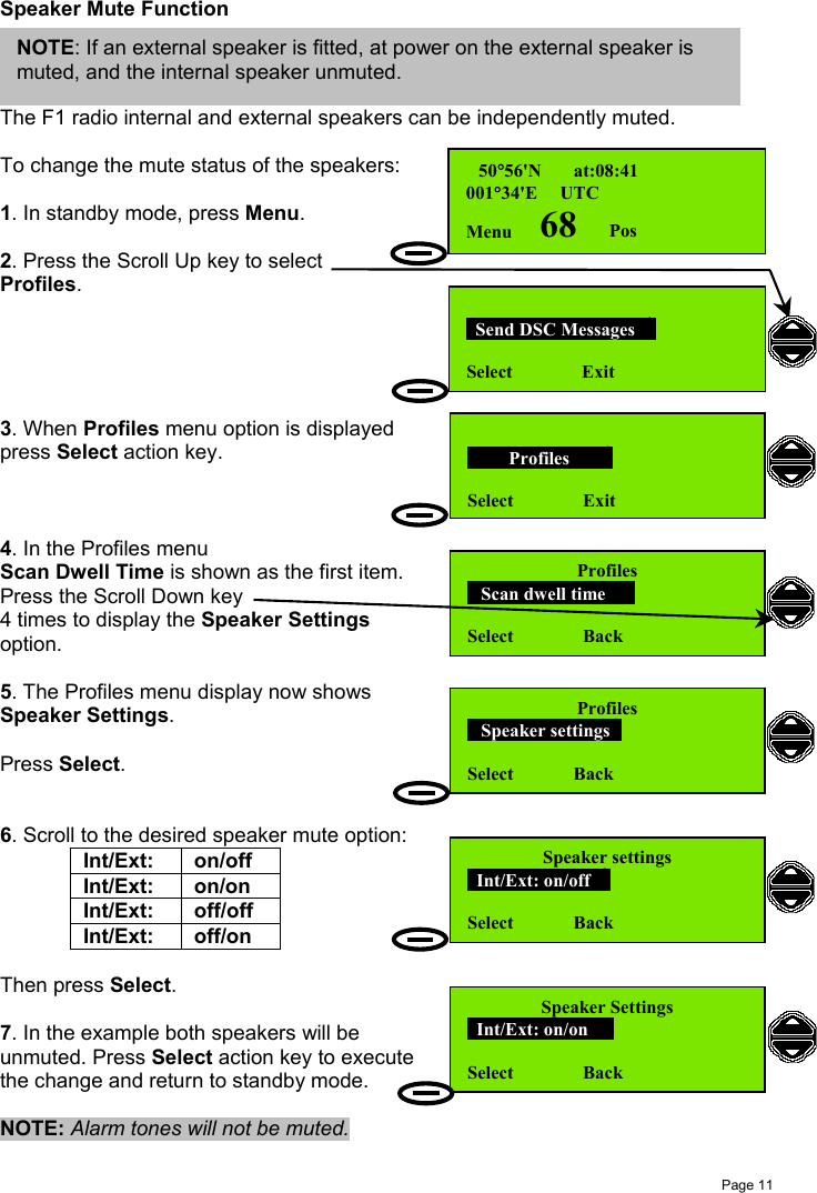
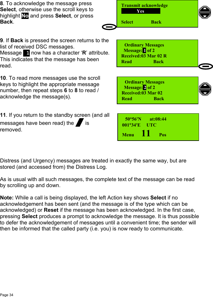
![Page 8 a b c7pqrs#2abcReceiving and TransmittingThe radio will operate as a basic transceiver for verbal communication withoutrequiring any information programmed into it.However, it cannot be used as a DSC communication system before it has a 'profile'set into it (i.e. as a minimum, the MMSI number must be set).Please refer to the 'Setting Profiles' section 'Setting the MMSI' for more information.Listening for Voice Communications (Telephony Calls)To prepare to listen to telephony calls:1. Ensure the radio is in the standby state(standby screen is shown here) using theaction keys if necessary.2. Set the radio to an appropriate channel. This is normally channel 16 (the radio isdesigned to monitor channel 16 by default). If a different listening channel isrequired press the scroll keys: or to increase or decrease the channelnumber, or use the numeric keys to set the channel directly. See also ‘PrivateChannels’.3. Set volume control to a comfortable level. A suitablestarting level is with the volume control rotated fully anti-(counter) clockwise and then rotated a few degreesclockwise.4. (a) Rotate the squelch control fully clockwise to‘squelch’ the channel, (b) then rotate slowly anti-clockwise until noise is heard on the free channel,(c) then rotate slightly clockwise to squelch the channelagain.5. Readjust the volume control if necessary. If sound cannot be heard, check thatthe internal speaker is enabled (go to Profiles->Speaker settings).Private ChannelsTo select a Private Channel (example P1, M2):1. Press the key then thekey (for P).2. Press3. You have now selected Private Channel P2.Subject to certain restrictions, your Service Agent can set up your Private Channels.[See also ‘Setting Channel Numbers’ on page 9.] 50°56'N at:08:40001°34'E UTCMenu 16 Pos 50°56'N at:08:40001°34'E UTCMenu P Pos 50°56'N at:08:40001°34'E UTCMenu P2 Pos](https://usermanual.wiki/Orolia/F1DSC.Operator/User-Guide-288626-Page-18.png)
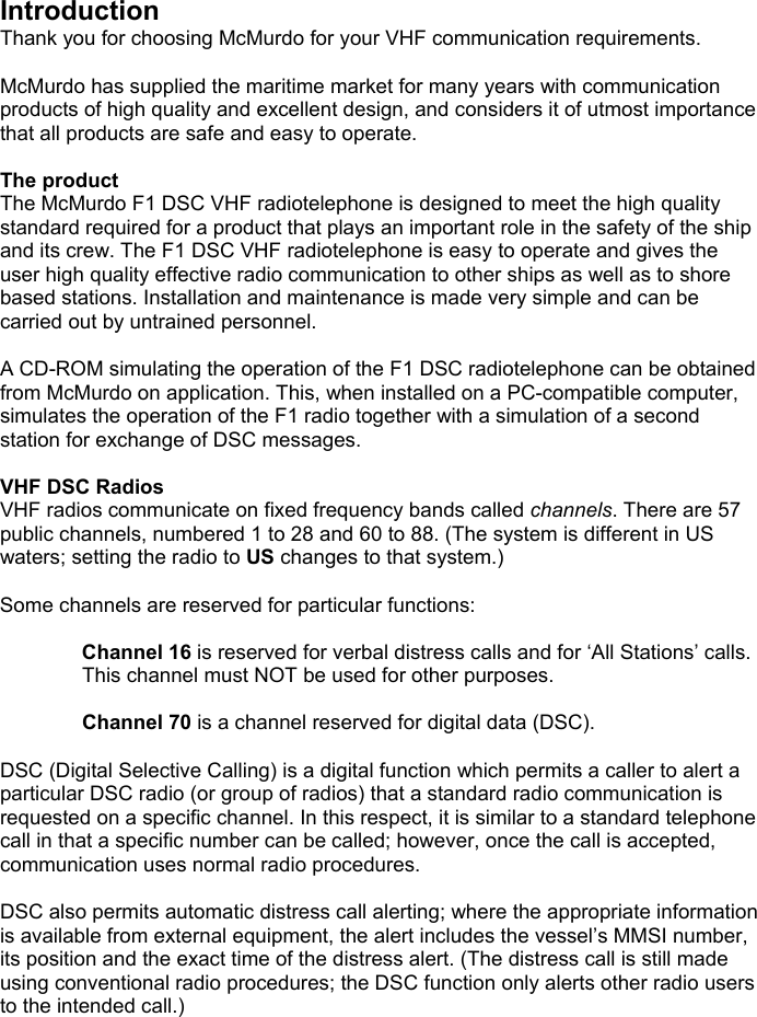
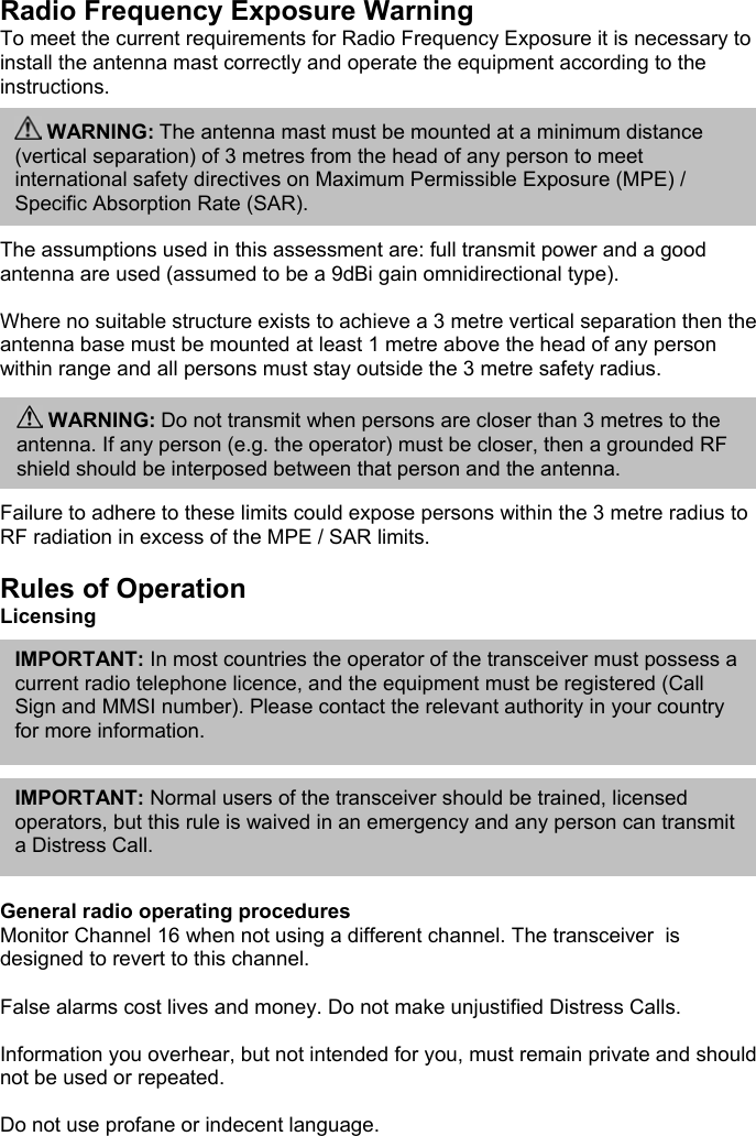
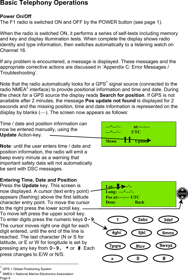
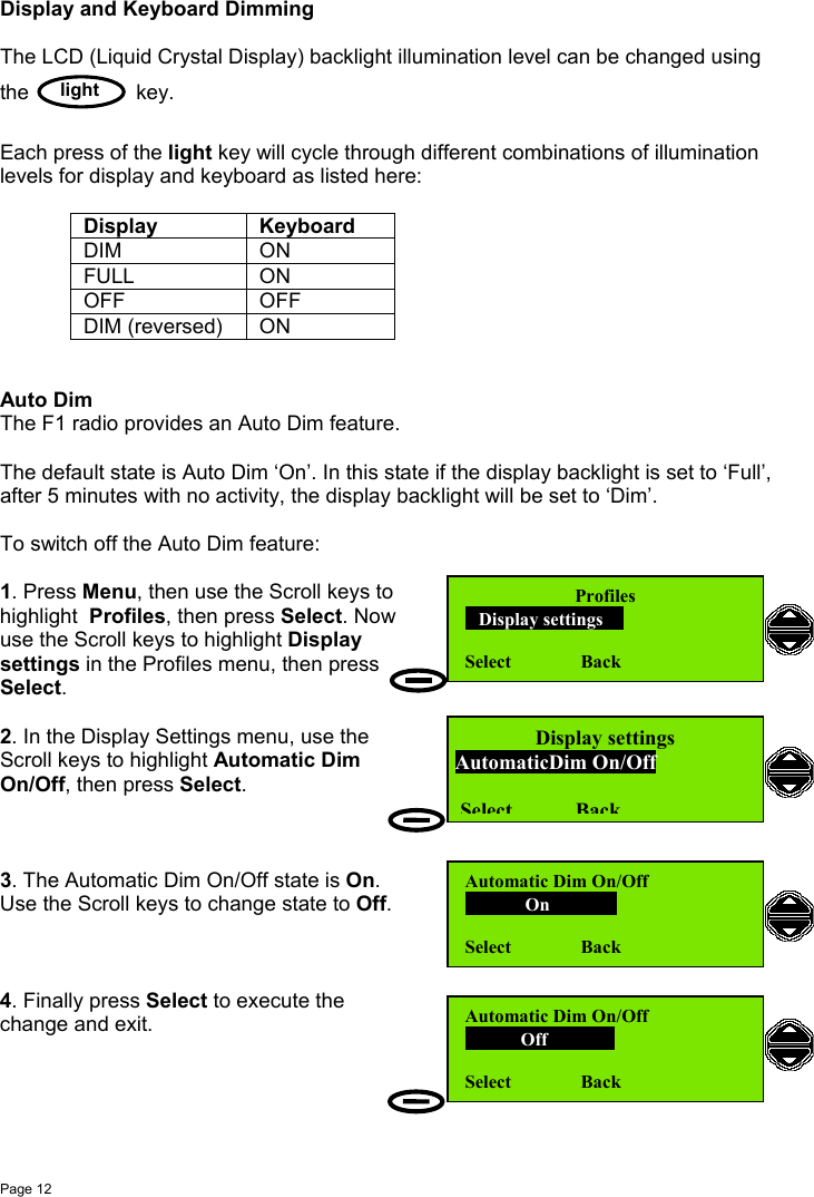
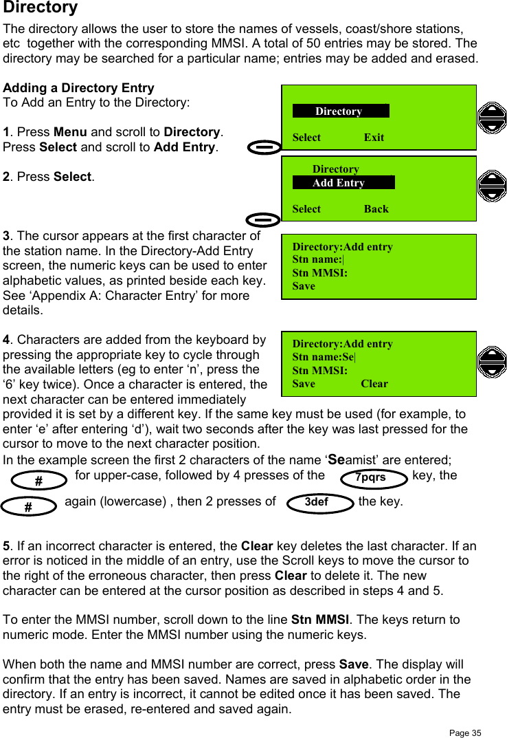
![Page 91/25Receiving Telephony (Voice) CallsWhen a call is received and the call sign ofyour vessel (or station name) is heard inloudspeaker (or handset where appropriate):1. Pick-up the fist-microphone or handset andpress and hold the PTT key, to answer the call.2. Say:‘<CALLING STATION NAME>This is <YOUR STATION NAME>’.3. Say: ‘Over’then release the PTT key and wait for anacknowledgement from the caller, which shouldinclude the new working channel (if suggested).4. Set the radio to the working channel (please referto the Setting Channel Numbers section) beforeresuming communication.For normal communications, very near to coasts,in ports and marinas, use the 1W power setting.(Press the key until the 1W LED is lit.)Setting Channel NumbersThe active channel is changed using the scrollkeys or by entering the channel number from thekeyboard, when in standby mode.To change a channel using the keyboard pressa numeric key (example ‘2’). The existing channelsetting clears and ‘2’ appears channel indicationsection of the display.If no other numeric key is pressed within 2seconds then the F1 radio is set to channel 2.If another numeric key is pressed (example ‘3’)then the displayed digit ‘2’ moves left by 1 digitposition and ‘3’ becomes the channel units digit.The radio is now set to channel 23.[See also ‘Private Channels’ on page 8.] 50°56'N at:08:40001°34'E UTCMenu 2 Pos 50°56'N at:08:41001°34'E UTCMenu 23 PosSeaMist.This is SunCruiser.(Goto) Channel 68.Over.NOTE: Press the PTT key only when talking. If a simplex channel is used (refer to Appendix D:Channel Specifications) it is necessary to say ‘Over’when you stop talking.NOTE: It is essential to propose a working channel forsubsequent communications(not Channel16). USTX1WPress / holdPTT keyRelease PTT key](https://usermanual.wiki/Orolia/F1DSC.Operator/User-Guide-288626-Page-19.png)
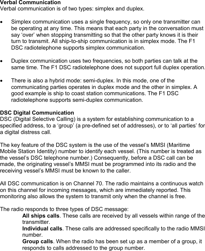
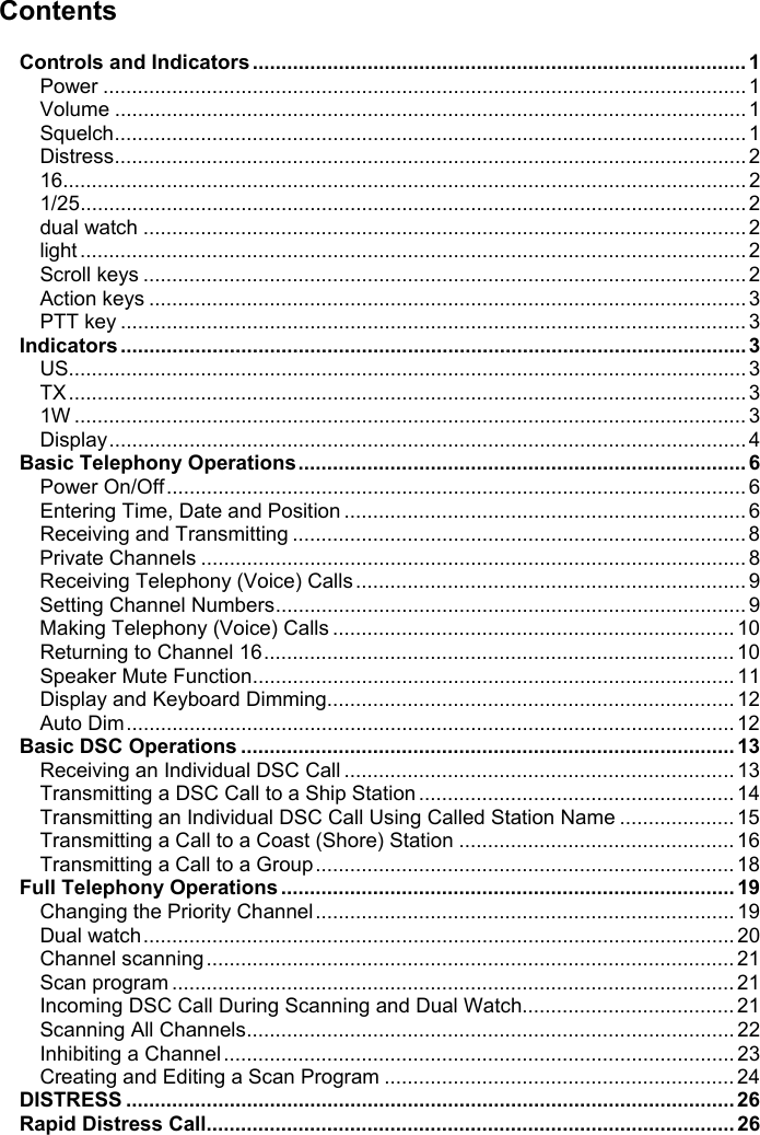
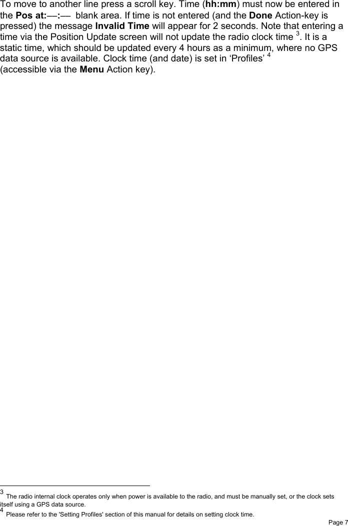
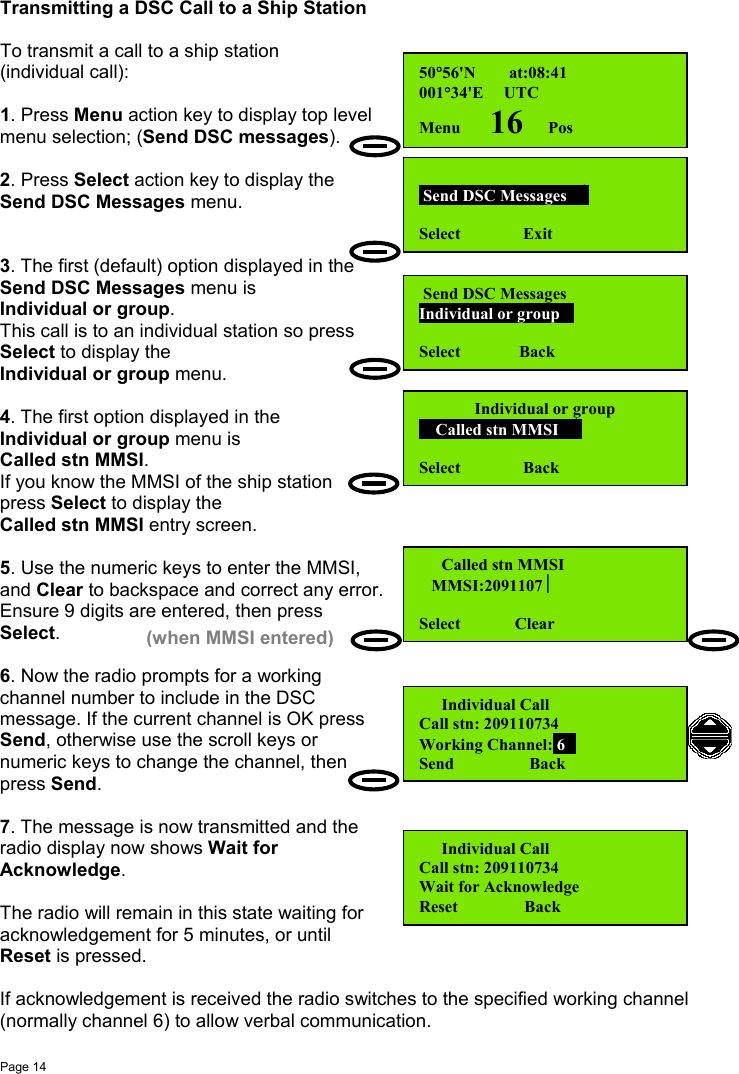
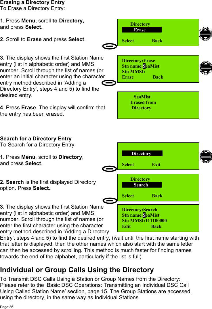
![Page 13Basic DSC OperationsAll DSC communication is on Channel 70. The radio maintains a continuous watchon this channel for incoming messages, which are immediately reported. Thismonitoring also allows the system to transmit only when the channel is free.Receiving an Individual DSC CallWhen the radio receives an individual DSC message an alarm will sound, and themessage Individual Call is displayed.If the call type is 'Distress' or 'Urgency' thealarm ('notify beep') will sound repeatedlyevery second. This screen will remain untilyou Read the message or Exit.To read the message:1. Press Read action key (or any key).Alarm tone is cancelled.2. Press Read key again to go to Read mode.3. The Read mode screen is displayed,and the message details are now shown; if necessary, scroll up and down to displaythe complete message. To acknowledge the message press Select.4. You now have a choice:Transmit Acknowledge?• Yes (default)• No.Use the scroll keys to change the optionto acknowledge the received message.5. Press Select to transmit a DSCacknowledgement. A DSC Acknowledgemessage is transmitted and the display brieflyshows Acknowledge sent and the MMSI ofthe called station. The radio now switches tothe caller proposed channel ready forcommunication. Press Reset to restore theoriginal channel, if desired.Individual CallRead 16 ExitIndividual: Safety15 Jan 02 UTC:07:43From stn: 987654321Select 16 BackTransmit acknowledge Yes Select Back[Press Read][Press Read]50°56'N at:08:41001°34'E UTCReset 6 PosNOTE: Normal practice is to acknowledge areceived DSC message, especially Distress orUrgency messages. Acknowledge sentCalled stn:987654321NOTE: If the call type is ‘Safety’ or‘Routine’ the alarm will sound twice only.If the message is not read within 1 minutethe radio will return to standby mode.](https://usermanual.wiki/Orolia/F1DSC.Operator/User-Guide-288626-Page-23.png)

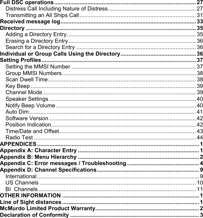
![Page 23Inhibiting a ChannelTo Inhibit a Channel when Scanning:1. The scan program is now running.The Scan ALL run screen is displayed.Press Stop.2. The screen now displays the new scanstatus:Inhibit chXX, where XX was the channelwhen Stop was pressed. Example: Ch25.Press Select.The scan program is now running again,But channel 25 is now temporarily deletedfrom the list of channels to be scanned, andthe radio will skip over channel 25 whenselecting channels during the scan process.Channel inhibition can be applied to additional channels, and is performed exactlyas described in steps 1 and 2 above.To restore the original 'Scan All' state (all channels scanned) press the Back keythen the Select key. Scanning is then resumed for all channels.Running a Scan Program (1-9)To Run a Scan Program (Scan Program 1 to Scan Program 9):1. In standby screen, press Menu, then scrollto Channel scanning and press Select.2. Scroll to Run scan program and pressSelect.3. Display shows Scan: ALL.Scroll to Scan: 01 (or to the Scan Program ofyour choice. When the desired Scan Programis displayed press Select to start the ScanProgram.[See also ‘Full Telephony Operations: Creating and Editing a Scan Program’ page24.] Scan:ALL stopped Inhibit ch25 Select Run Scan:ALL runStop 24 Back Scan:ALL runStop 26 Back Channel scanning Run scan program Select Back Run scan program Scan: 01Select Back](https://usermanual.wiki/Orolia/F1DSC.Operator/User-Guide-288626-Page-33.png)
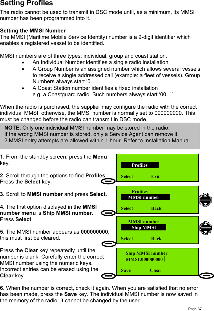
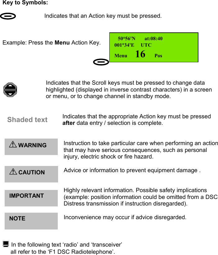
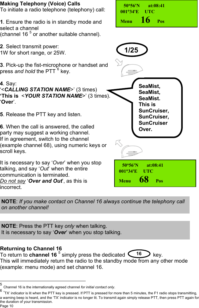
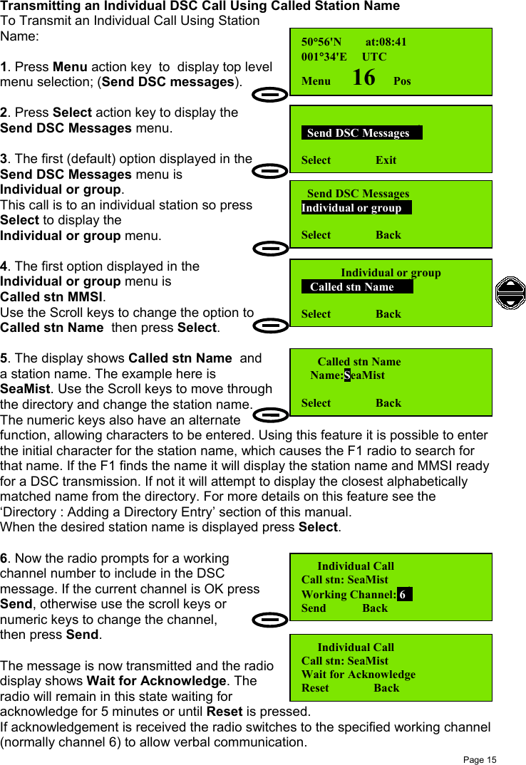
![Page 38Group MMSI NumbersA radio may be a member of up to 4 MMSI groups (for example, a group MMSIcould be assigned to a fishing fleet).Setting a group MMSI is similar to the process for setting the individual MMSI.1. After selecting Profiles – MMSI number,scroll to Group MMSI and press Select.Group 1 is displayed first;Groups 2, 3, and 4 are displayed by scrolling.2. Press Edit to enter the Group MMSInumber. When entering the MMSI number, thefirst ‘0’ cannot be changed (because itidentifies a MMSI as a group number). TheBack Action key changes to Clear as youenter digits.3. When the Group MMSI is entered, pressSave. The Edit screen, showing the groupMMSI is then displayed and it is possible toEdit the number again, or use the Back / Exitkey to return to the standby screen.Unlike the individual MMSI number, Group MMSIs can be edited and deleted.Scan Dwell TimeThe Scan Dwell Time is the length of time the radio monitors each channel when inScan mode.To set the Scan Dwell Time:1. In standby screen, press Menu, then scrollto Profiles and press Select.2. Scan dwell time is the first optiondisplayed. Press Select.3. The Dwell Time is changed using the Scrollkeys. Time increments / decrements are50ms. Press Save when the desired dwelltime is displayed. MMSI number Group MMSI Select Back Group MMSI number Group 1: Edit Back Group MMSI number Group 1:0|Save Back Profiles Select Exit Profiles Scan dwell time Select Back Scanning [msec] Set dwell time: 200Save Back](https://usermanual.wiki/Orolia/F1DSC.Operator/User-Guide-288626-Page-48.png)

![Page 41LCD Contrast AdjustThis control allows the contrast of the LCD display, and thus the viewing angle ofthe screen, to be adjusted using the Scroll keys.To set the Contrast Level:1. In standby screen, press Menu, then scrollto Profiles and press Select.2. Scroll to Display settings and pressSelect.3. The first option displayed in the Displaysettings menu is LCD contrast adjust.Press Select.4. Scroll through contrast levels 0-30. Whenthe desired level is reached press Select.(Default level is 15).If the screen becomes dark and cannot be adjusted by the scroll keys, press theright action key (the Back button) to return to the previous setting.Auto DimThe F1 radio provides an Auto Dim feature.The default state is Auto Dim ‘On’. In this state if the display backlight is set to ‘Full’,after 5 minutes with no activity, the display backlight will be set to ‘Dim’.To change the settings of this feature:1. In standby screen, press Menu, then scrollto Profiles and press Select.2. Scroll to Display settings and pressSelect.3. Scroll to Automatic Dim On/Offand press Select.4. Scroll between On and Off states. Whenthe desired state is shown press Select.[See also 'Basic Telephony operations: Display and Keyboard Dimming' section,page 12.] Profiles Display settings Select Back Display settingsLCD contrast adjust Select BackLCD contrast adjust 15Select Back Profiles Display settings Select Back Display settingsAutomatic Dim On/OffSelect BackAutomatic Dim On/Off OnSelect Back](https://usermanual.wiki/Orolia/F1DSC.Operator/User-Guide-288626-Page-51.png)