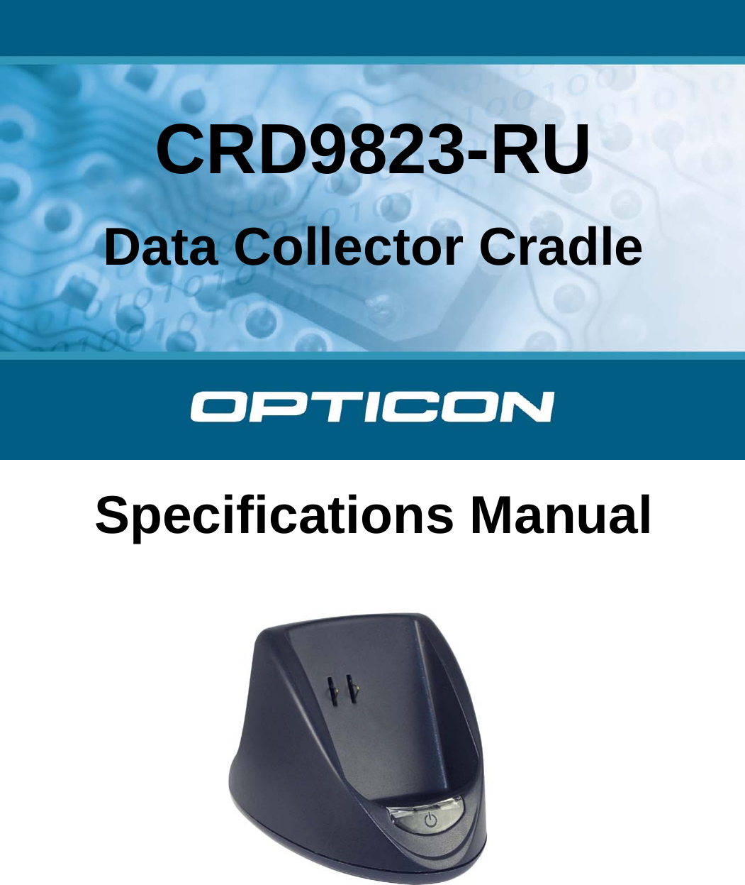
Opticon Sensors Europe PX36 Barcode data collector User Manual CRD 9723 Single Bay Specification Manual

Opticon Sensors Europe BV Barcode data collector CRD 9723 Single Bay Specification Manual
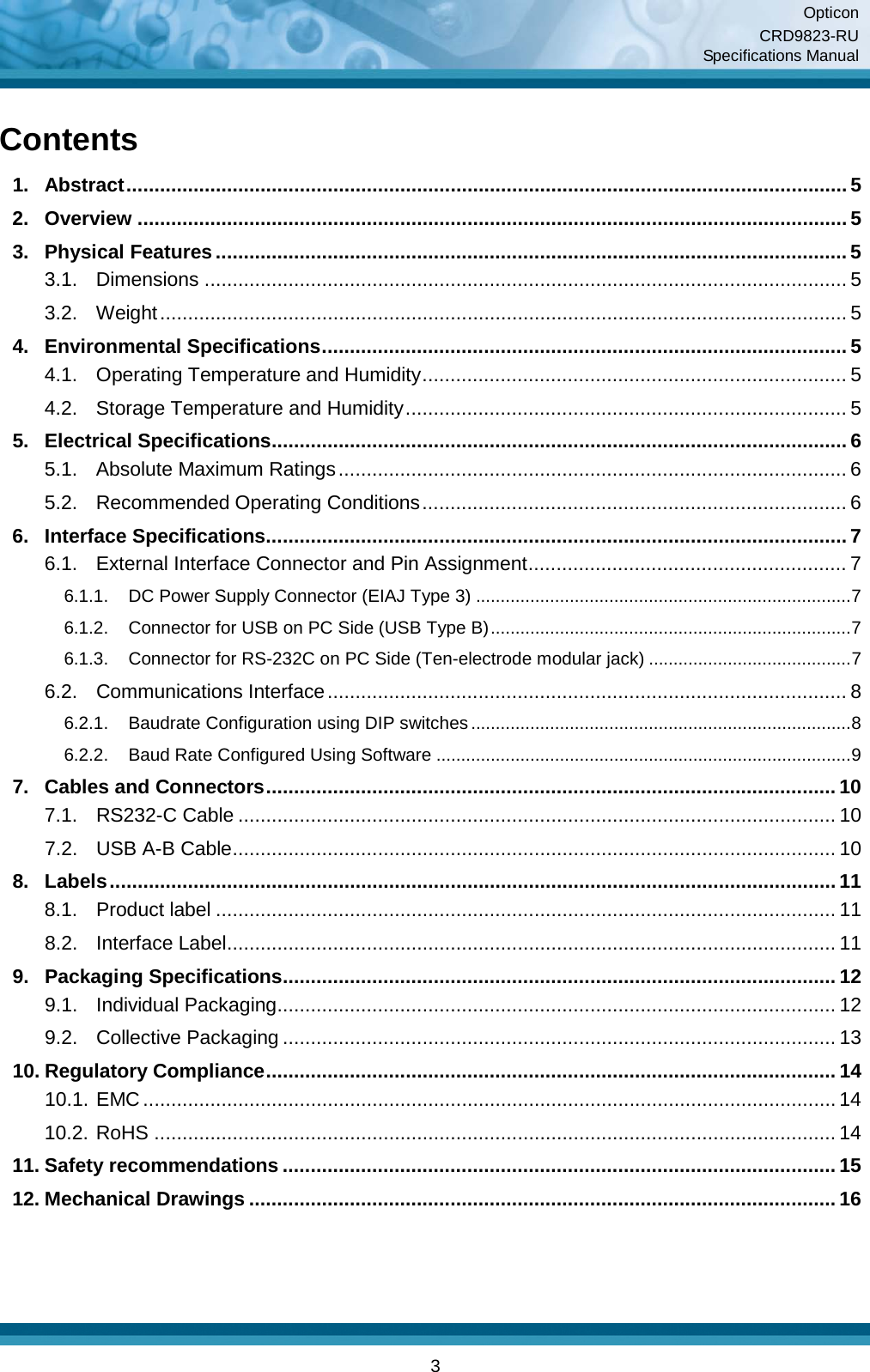
Contents

Manual of Cradle

  CRD9823-RU Data Collector Cradle  Specifications Manual
Opticon CRD9823-RU Specifications Manual     2 All information subject to change without notice. Document History Model Number: CRD9823 RU   Specification Number:  Edition: 1  Original Spec Number:  Date: 2014-01-03   Copyright 2014 Opticon. All rights reserved. This manual may not, in whole or in part, be copied, photocopied, reproduced, translated or converted to any electronic or machine readable form without prior written consent of Opticon. Limited Warranty and Disclaimers PLEASE READ THIS MANUAL CAREFULLY BEFORE INSTALLING OR USING THE PRODUCT. Serial Number  A serial number appears on all Opticon products. This official registration number is directly related to the device purchased. Do not remove the serial number from your Opticon device. Removing the serial number voids the warranty. Warranty Unless otherwise agreed in a written contract, all Opticon products are warranted against defects in materials and workmanship for two years after purchase. Opticon will repair or, at its option, replace products that are defective in materials or workmanship with proper use during the warranty period. Opticon is not liable for damages caused by modifications made by a customer. In such cases, standard repair charges will apply. If a product is returned under warranty and no defect is found, standard repair charges will apply. Opticon assumes no liability for any direct, indirect, consequential or incidental damages arising out of use or inability to use both the hardware and software, even if Opticon has been informed about the possibility of such damages.  Packaging The packing materials are recyclable. We recommend that you save all packing material to use should you need to transport your scanner or send it for service. Damage caused by improper packaging during shipment is not covered by the warranty. Trademarks Trademarks used are the property of their respective owners. Opticon Inc. and Opticon Sensors Europe B.V. are wholly owned subsidiaries of OPTOELECTRONICS Co., Ltd., 5-3, Tsukagoshi 5-chome, Warabi-shi, Saitama, Japan 335-0002. TEL +81-(0) 48-446-1183; FAX +81-(0) 48-446-1180 SUPPORT USA Europe Phone: 800-636-0090   Email: support@opticonusa.com Email: support@opticon.com Web: www.opticonusa.com Web: www.opticon.com
Opticon CRD9823-RU Specifications Manual     3 Contents 1. Abstract ................................................................................................................................. 5 2. Overview ............................................................................................................................... 5 3. Physical Features ................................................................................................................. 5 3.1. Dimensions ................................................................................................................... 5 3.2. Weight ........................................................................................................................... 5 4. Environmental Specifications .............................................................................................. 5 4.1. Operating Temperature and Humidity ............................................................................ 5 4.2. Storage Temperature and Humidity ............................................................................... 5 5. Electrical Specifications ....................................................................................................... 6 5.1. Absolute Maximum Ratings ........................................................................................... 6 5.2. Recommended Operating Conditions ............................................................................ 6 6. Interface Specifications ........................................................................................................ 7 6.1. External Interface Connector and Pin Assignment ......................................................... 7 6.1.1. DC Power Supply Connector (EIAJ Type 3) ............................................................................ 7 6.1.2. Connector for USB on PC Side (USB Type B) ......................................................................... 7 6.1.3. Connector for RS-232C on PC Side (Ten-electrode modular jack) ......................................... 7 6.2. Communications Interface ............................................................................................. 8 6.2.1. Baudrate Configuration using DIP switches ............................................................................. 8 6.2.2. Baud Rate Configured Using Software .................................................................................... 9 7. Cables and Connectors ...................................................................................................... 10 7.1. RS232-C Cable ........................................................................................................... 10 7.2. USB A-B Cable ............................................................................................................ 10 8. Labels .................................................................................................................................. 11 8.1. Product label ............................................................................................................... 11 8.2. Interface Label ............................................................................................................. 11 9. Packaging Specifications ................................................................................................... 12 9.1. Individual Packaging .................................................................................................... 12 9.2. Collective Packaging ................................................................................................... 13 10. Regulatory Compliance ...................................................................................................... 14 10.1. EMC ............................................................................................................................ 14 10.2. RoHS .......................................................................................................................... 14 11. Safety recommendations ................................................................................................... 15 12. Mechanical Drawings ......................................................................................................... 16
Opticon CRD9823-RU Specifications Manual     4 Table of Figures Figure 1: DIP switch settings ..................................................................................................... 8 Figure 2: Signal timing when software is configured .................................................................. 9 Figure 3: RS-232C cable ......................................................................................................... 10 Figure 4: USB cable ................................................................................................................ 10 Figure 5: Product  label on the bottom of the cradle ................................................................. 11 Figure 6: Label on the back side of the cradle .......................................................................... 11 Figure 7: Individual packaging specification ............................................................................ 12 Figure 8: Collective packaging specification ............................................................................ 13 Figure 9: Mechanical drawing ................................................................................................. 16
Opticon CRD9823-RU Specifications Manual     5 1. Abstract This manual provides specifications for the CRD9823-RU cradle designed for the Opticon OPL (OPL97XX and OPL98XX) series data collectors. The CRD9823-RU cradle supports USB and RS232 interfaces and can also used to charge the OPL. 2. Overview The CRD9823-RU cradle can be used to charge the OPL series data collectors. Additionally, it provides a way for data communication between the OPL data collector and a host computer. The Opticon OPL data collectors all have an IrDA communication interface and this cradle acts as a bridge between the USB/RS232 interface available on every computer and the IrDA interface in the OPL data collector.  The CRD9823-RU communicates with the OPL data collectors via infrared data communication (IrDA1.2, low-power) and can communicate with a host computer via either USB (USB 2.0, CDC class virtual comm. port) or RS232C.  The CRD9823-RU has three status LED’s, a red LED that indicates that the power is switched on, a green LED that blinks when the cradle receives data via IrDA and a yellow LED that blinks when data is received via USB or RS232.  The baud rate for RS232 & IrDA can be configured via special software on the host computer but it can also be configured via a block of switches that are accessible via the bottom of the cradle. Supported baud rates are 1200, 2400, 4800, and 9600 bps, 19.2kbps, 38.4kbps, 57.6kbps and 115.2 kbps.   3. Physical Features 3.1. Dimensions W 98.5 x D 71.5 x H 67.0 mm 3.2. Weight 80 g 4. Environmental Specifications 4.1. Operating Temperature and Humidity Temperature: 0 to 40° C (32 to 104° F) Humidity: 30 to 80% 4.2. Storage Temperature and Humidity Temperature: -20 to 60° C (-4 to 140° F) Humidity: 30 to 90%
Opticon CRD9823-RU Specifications Manual     6 5. Electrical Specifications Only use dedicated Opticon approved AC adapters with this cradle. The output of such a AC adapter should be 6V/2A. It is not possible to power the cradle via USB.   5.1. Absolute Maximum Ratings Parameter Value Unit Power supply voltage (VCC to GND)  -0.3 to 6.5  V Input voltage (D+, D-)  -0.5 to 0.5  V Input voltage (RS-232C IN) ±30  V Input voltage (RS-232C OUT) ±15  V 5.2. Recommended Operating Conditions Item Symbol Conditions Min Typ Max Unit Power supply voltage  VDD DC power supply  5.5  6.0 6.5  V
Opticon CRD9823-RU Specifications Manual     7 6. Interface Specifications 6.1. External Interface Connector and Pin Assignment 6.1.1. DC Power Supply Connector (EIAJ Type 3) Pin Signal Name Notes Inward +6 V Power supply +6 V Outward GND Ground 6.1.2. Connector for USB on PC Side (USB Type B) Pin Signal Name I/O Notes 1  VBUS  P  USB bus power supply 2  D-  I/O  Data - 3  D+ I/O Data + 4  GND  P  Ground 6.1.3. Connector for RS-232C on PC Side (Ten-electrode modular jack) Pin Signal Name I/O Notes 1  GND  P  Ground 2  CTS  I  For baud rate software control 3  TXD  O  Transmit data to PC 4  RXD  I  Receive data from PC 5  NC  -  Not connected 6  GND  P  Ground 7  NC  -  Not connected 8  DSR  I  For baud rate software control 9  NC  -  Not connected 10 GND  P  Ground
Opticon CRD9823-RU Specifications Manual     8 6.2. Communications Interface The baud rate can be configured via DIP switches on the bottom of the cradle. The baud rate can also be configured by using special software on the host. 6.2.1. Baud rate Configuration using DIP switches To disable software configuration, set SW4 to OFF. Baud rate can be configured using SW1–SW3 as listed in the table below.  Baud rate DIP Switch  SW1 SW2 SW3 SW4 115.2 kbps ON  ON ON OFF 57.6 kbps OFF ON ON OFF 38.4 kbps ON OFF ON OFF 19.2 kbps OFF OFF ON OFF 9600 bps ON ON OFF OFF 4800 bps OFF ON OFF OFF 2400 bps ON OFF OFF OFF 1200 bps OFF OFF OFF OFF     Figure 1: DIP switch settings Remove the cover and change the settings. Put the cover back on when finished.
Opticon CRD9823-RU Specifications Manual     9 6.2.2. Baud Rate Configured Using Software To allow configuration using software on the host computer, set SW4 to ON. The other DIP switches are not used when SW4 is ON.  CTS Line DSR Line Baud Rate Remarks  Edge 0 pulse 115.2 kbps Reset Pulse Count  1 pulse 57.6 kbps    2 pulse 38.4 kbps    3 pulse 19.2 kbps    4 pulse 9600 bps    5 pulse 4800 bps    6 pulse 2400 bps    7 pulse  1200 bps     Figure 2: Signal timing when software is configured
Opticon CRD9823-RU Specifications Manual     10 7. Cables and Connectors 7.1. RS232-C Cable      Figure 3: RS-232C cable  Type:  Straight Diameter: φ3.8 ±0.15 mm Length: 1500 ±100, -0 mm Cores: 8 insulated wires, 1 conductive wire Connectors Left   RJ50 (10-pin modular jack) Right   DB9, female 7.2. USB A-B Cable    Figure 4: USB cable  Type:  Straight Diameter: Φ4.7 ±0.15 mm Length: 1500 ±50 mm Cores: 4 insulated wires, 1 conductive wire Connectors Left   USB-B type Right USB-A type
Opticon CRD9823-RU Specifications Manual     11 8. Labels The serial number shown below is affixed to the specified location on the cradle. 8.1. Product label  Figure 5: Product  label on the bottom of the cradle 8.2. Interface Label  Figure 6: Label on the back side of the cradle
Opticon CRD9823-RU Specifications Manual     12 9. Packaging Specifications 9.1. Individual Packaging Put the cradle in a protective foam bag and place it in an individual packing box.    Figure 7: Individual packaging specification
Opticon CRD9823-RU Specifications Manual     13 9.2. Collective Packaging   Figure 8: Collective packaging specification  Note: The “RO” mark labeled on the package tray or package box guarantees that the applicable product has passed our test of RoHS restrictions compliance (the restriction of the use of certain hazardous substances in electrical and electronic equipment, 2002/95 EC). However, this document does not have any legal weight in the European Union.
Opticon CRD9823-RU Specifications Manual     14 10. Regulatory Compliance 10.1. EMC EN55022 EN55024 FCC Part 15 Subpart B Class B: This device complies with part 15 of the FCC Rules. Operation is subject to the following two conditions: (1) this device may not cause harmful interference, and (2) this device must accept any interference received, including interference that may cause undesired operation. 10.2. RoHS RoHS: The restriction of the use of certain hazardous substances in electrical and electronic equipment, 2002/95 EC.
Opticon CRD9823-RU Specifications Manual     15 11. Safety recommendations Handle this product carefully. Do not subject it to any of the following.  Shock • Do not throw or drop the cradle.  • Do not place heavy objects on the cables. Temperature Conditions • Do not use the cradle at temperatures outside the specified operating temperature range.  • Do not subject the cradle to temperatures outside the specified storage temperature range.  • Do not forcibly bend the cables, especially at low temperatures. Foreign Materials • Do not immerse the cradle in liquids. • Do not subject the cradle to chemicals. Other • Do not disassemble this product. • This cradle may degrade the reception of nearby radio/television sets. • The cradle may be damaged by high voltage spikes such as caused by lightning.  • The cradle may not operate properly when placed very close to a cellular phone.
Opticon CRD9823-RU Specifications Manual     16 12. Mechanical Drawings Dimensions: W 98.5 x D 71.5 x H 67.0 mm  Figure 9: Mechanical drawing  No. Name   1  DC jack DC jack for the dedicated AC adapter 2  USB connector USB communication connector to the host computer 3  RS-232C connector RS-232C communication connector to the host computer  4  Power LED (Red) Red LED lights when the power is on 5  IrDA reception LED (Green) Green LED blinks when receiving data via IrDA 6  IrDA transmission LED (Yellow) Yellow LED blinks when transmitting data via IrDA 7  IrDA communication window  IrDA communication window 8  Charging terminal (+) Charging Terminal (+) to the OPL-97xx  9  Charging terminal (-)  Charging Terminal (-) to the OPL-97xx 10 DIP switch To configure the baud rate.  11 Product label

Navigation menu