One World Technologies GD200 GDO200 main unit User Manual 2
One World Technologies, Inc. GDO200 main unit Users Manual 2
UserManual.wiki
>
One World Technologies
>
GD200 User Manual
>
Users Manual 2
Contents
1.
Users Manual 1
2.
Users Manual 2
3.
Users Manual 3
Users Manual 2
Navigation menu
Upload a User Manual
Namespaces
Wiki Guide
HTML
PDF
Info
Views
User Manual
Discussion / Help
Navigation
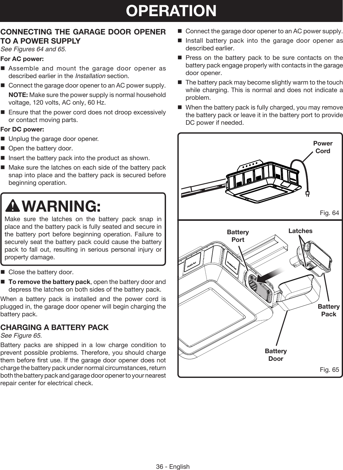
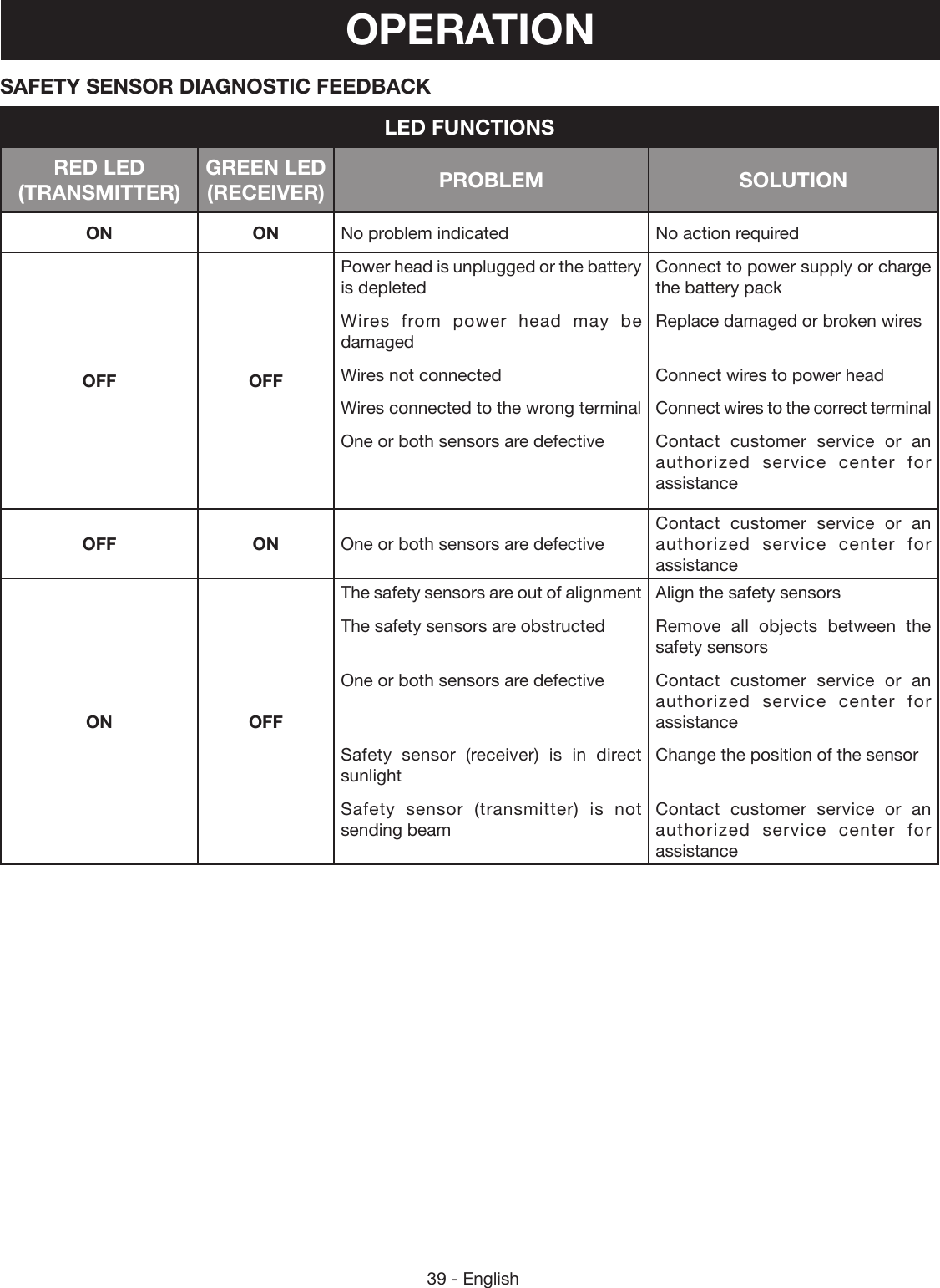
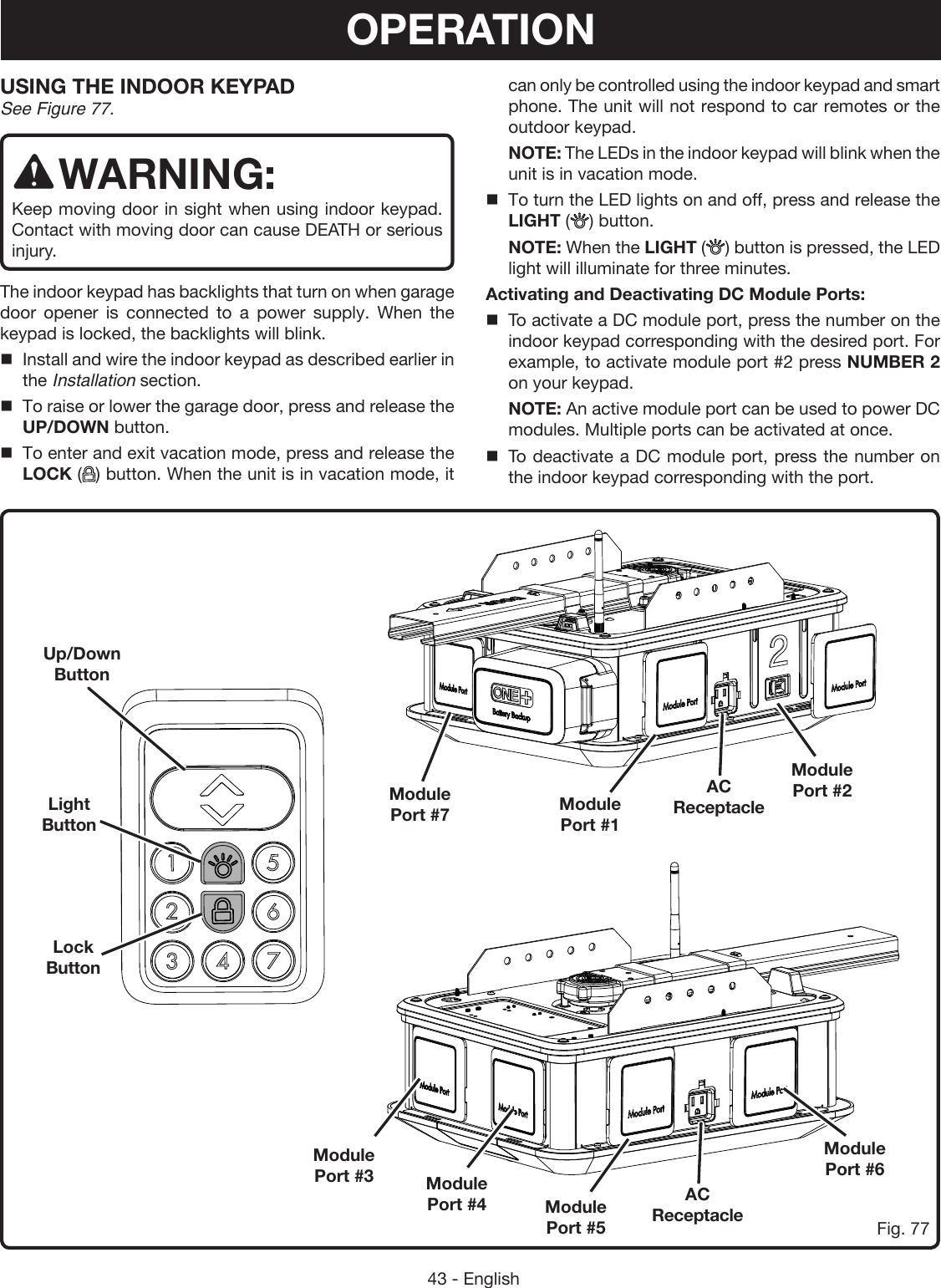
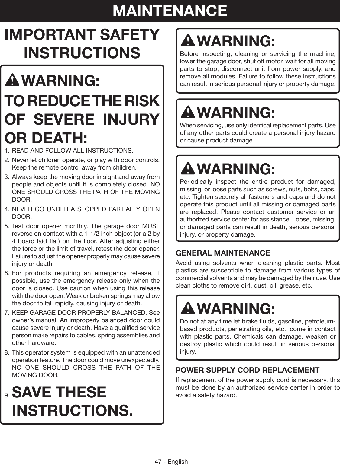
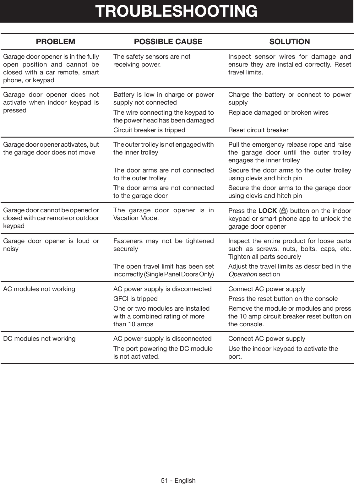
![29 - EnglishSectional DoorSectional DoorSectional DoorSectional DoorFig. 44Fig. 46Fig. 47Fig. 45CONNECTING DOOR BRACKET TO OUTER TROLLEY See Figures 44 - 49.Locate the following items: Curved Door Arm Straight Door Arm Medium Clevis Pin Small Clevis Pin Hitch pins (2) Bolts (M8 x 1 in.) [2] Lock Nuts (M8) [2]To connect sectional doors:Lower the garage door completely.Pull the emergency release rope down and slide outer trolley toward the garage door.Secure straight door arm to the rear of the outer trolley using medium clevis pin and hitch pin.Secure curved door arm to the door bracket using small clevis pin and hitch pin.Bring the curved and straight arms together. Choose two sets of aligned holes and install bolts and nuts. Tighten bolts and nuts with a 13 mm socket. NOTE: For better rigidity, install fasteners in holes that are as far apart as possible. NOTE: If the holes in the arm do not align, remove the straight door arm and reattach it in the reverse position.If the straight door arm hangs too low after assembly, you can shorten the length of the arm by cutting off up to 6 inches.Curved Door ArmHitch PinHitch PinClevis PinClevis PinStraight Door ArmBoltLock Nut Emergency Release RopeOuter TrolleyINSTALLATION](https://usermanual.wiki/One-World-Technologies/GD200.Users-Manual-2/User-Guide-2906780-Page-1.png)
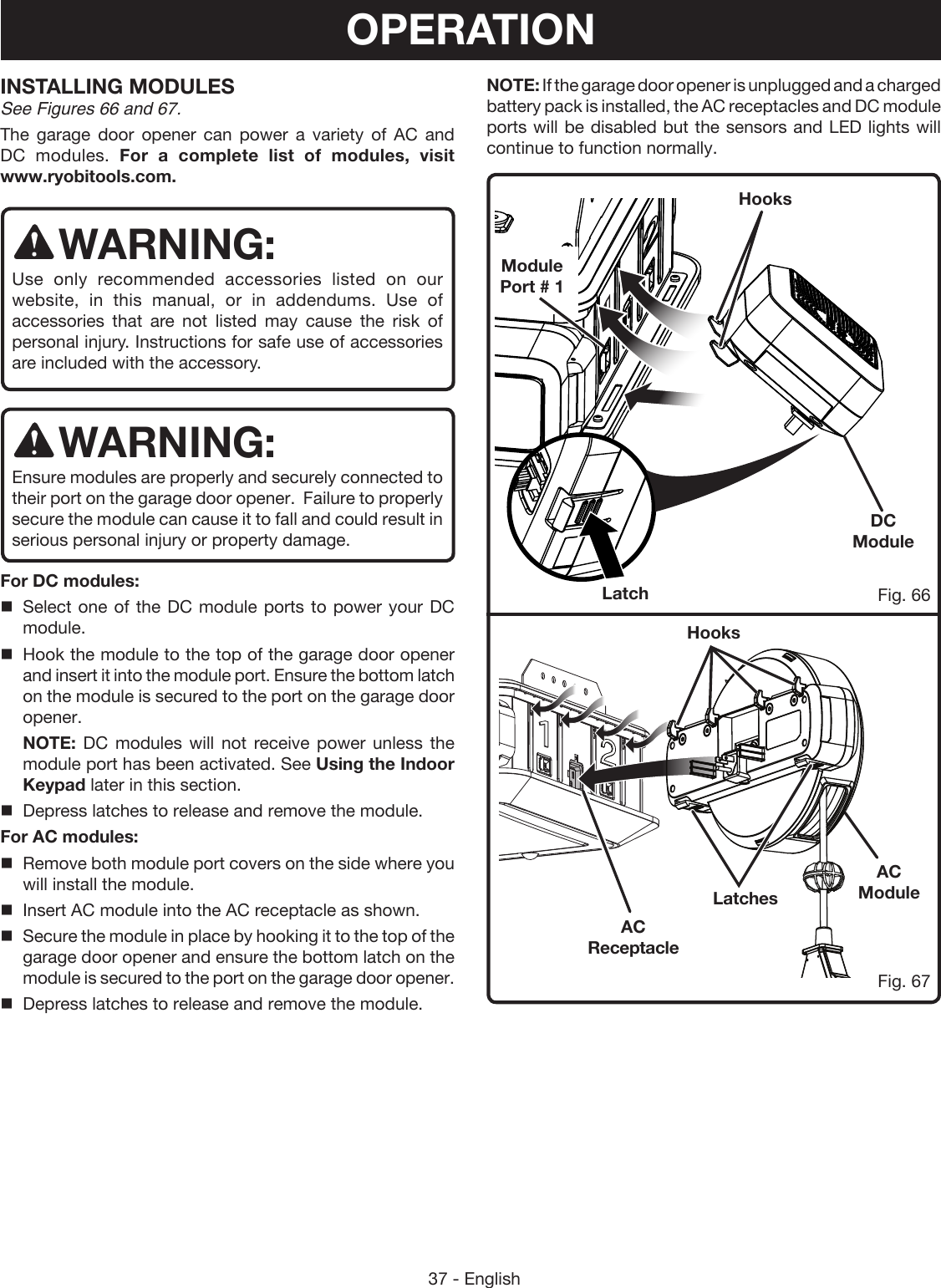
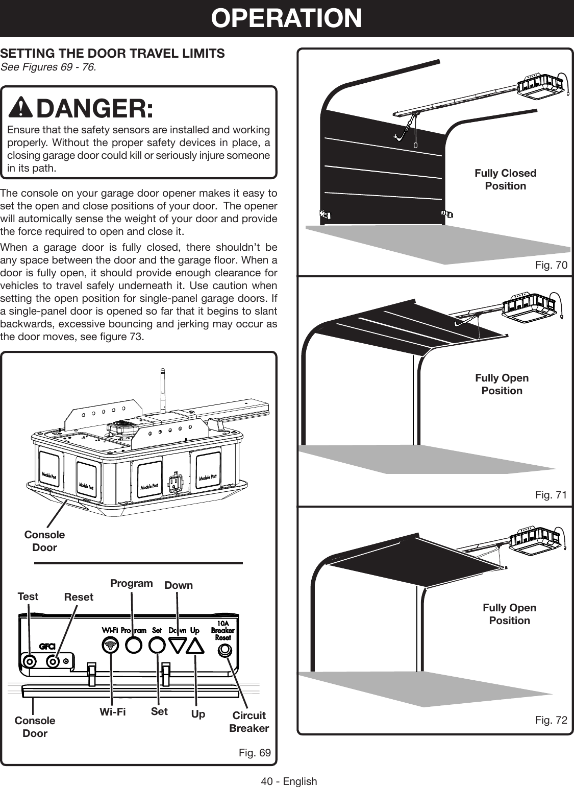
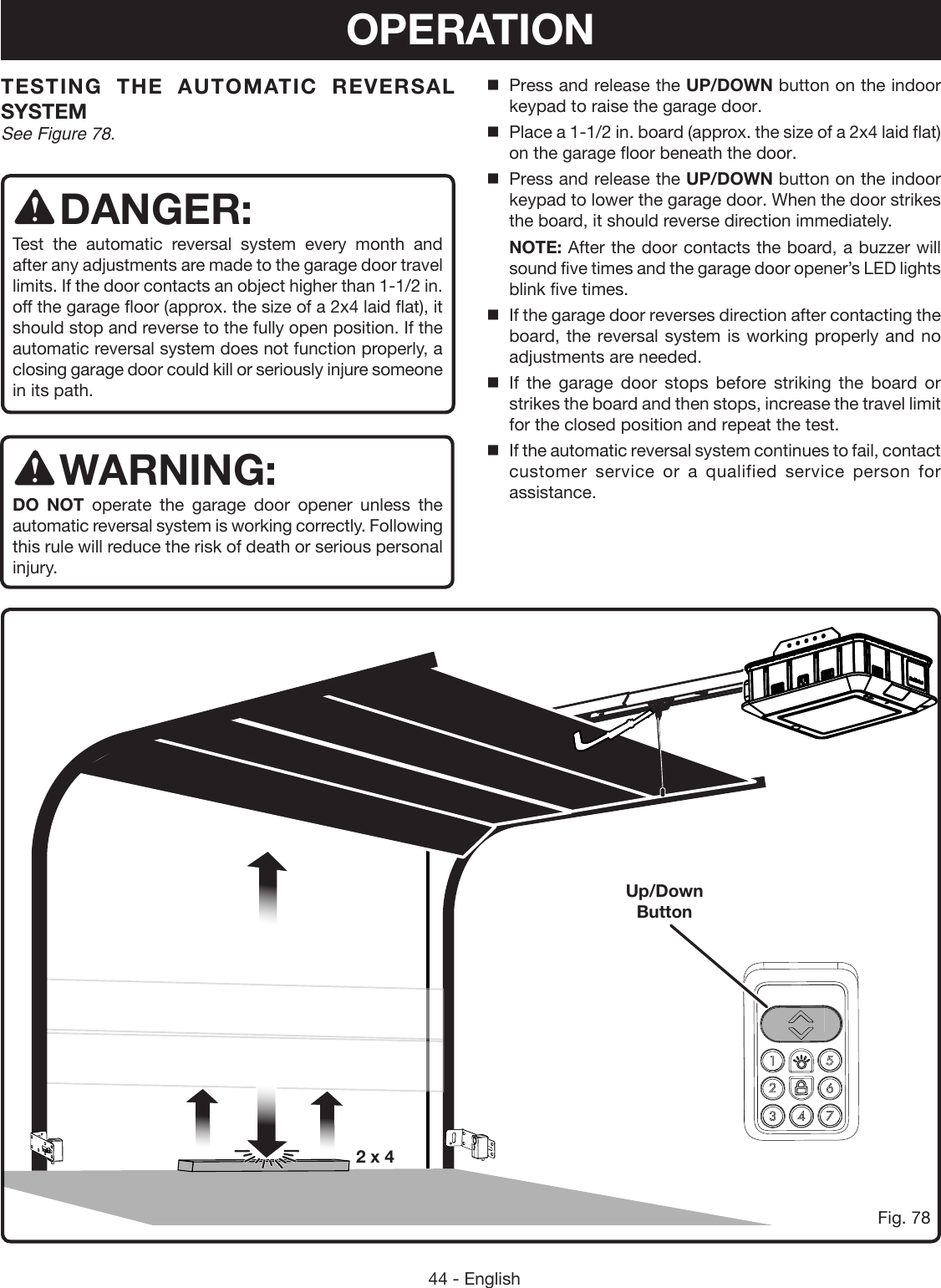
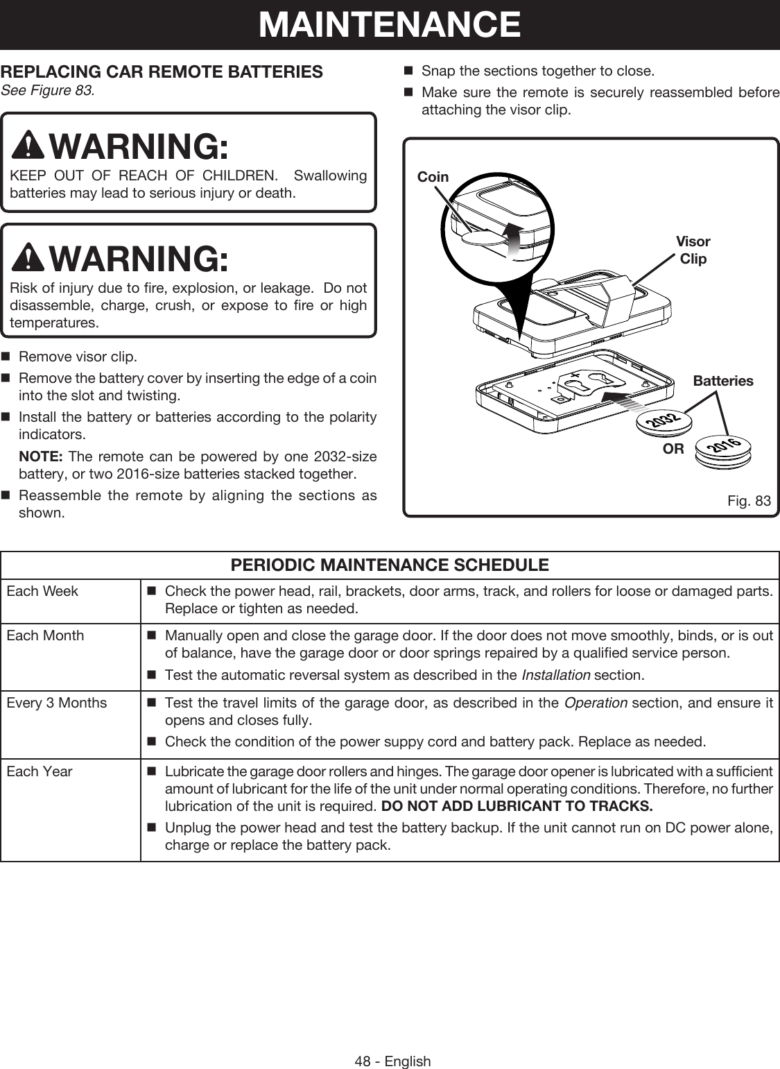
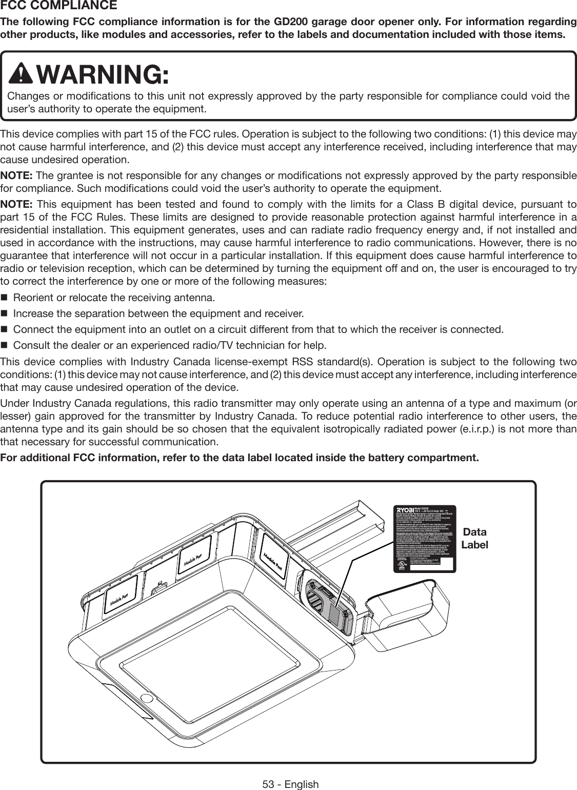
![30 - EnglishTo connect single-panel doors:Lower the garage door completely.Pull the emergency release rope down and slide outer trolley toward the garage door.Place the curved and straight arms together and align the holes.Choose two sets of aligned holes and install bolts and nuts. Tighten bolts and nuts with a 13 mm socket. NOTE: For better rigidity, install fasteners in holes that are as far apart as possible.Secure straight door arm to the door bracket using small clevis pin and hitch pin.Secure curved door arm to the rear of the outer trolley using medium clevis pin and hitch pin.INSTALLING THE SAFETY SENSORS See Figures 50 - 55.Locate the following items: Safety Sensors (2) Insulated Staples Wing Nut (2) Bracket (2) Nail (2 in.) [2] Lag Screw (M8 x 2 in.) [2]Fig. 48Fig. 49WARNING:DO NOT operate the garage door opener unless the safety sensors are installed and working correctly. Failure to properly install and ensure that the safety sensors are working correctly can result in death or serious personal injury. WARNING:The bottom of the safety sensor should be no higher than six inches above the garage floor. This will ensure that the door reverses should a child, pet, or small object move beneath the door as it lowers. Improper placement of the safety sensors can result in death or serious personal injury.WARNING:The effectiveness of the safety sensors included in this system directly relates to the placement and installation of the sensors. Incorrect placement or installation could prevent the sensors from working as intended and result in death or serious personal injury.Assemble the safety sensors by inserting the sensor stud through the long slot in the bracket and securing with a wing nut.Lower the garage door completely.Position both sensors on either side of the interior of the garage door about four to six inches above the garage floor and point the lenses toward each other. The arrow should be facing up.BoltHitch PinClevis PinClevis Pin StudWing NutSafety SensorLong SlotBracketHitch PinFig. 50Lock Nut Single Panel DoorSingle Panel DoorINSTALLATION](https://usermanual.wiki/One-World-Technologies/GD200.Users-Manual-2/User-Guide-2906780-Page-2.png)
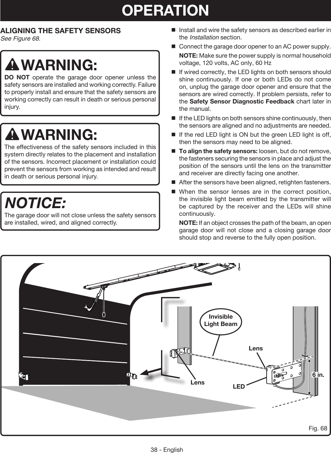
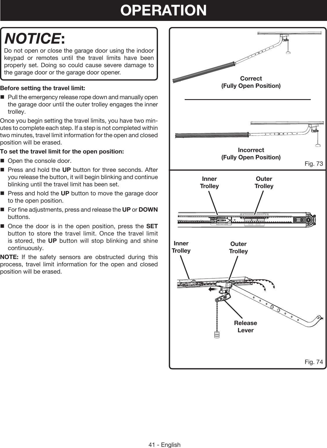
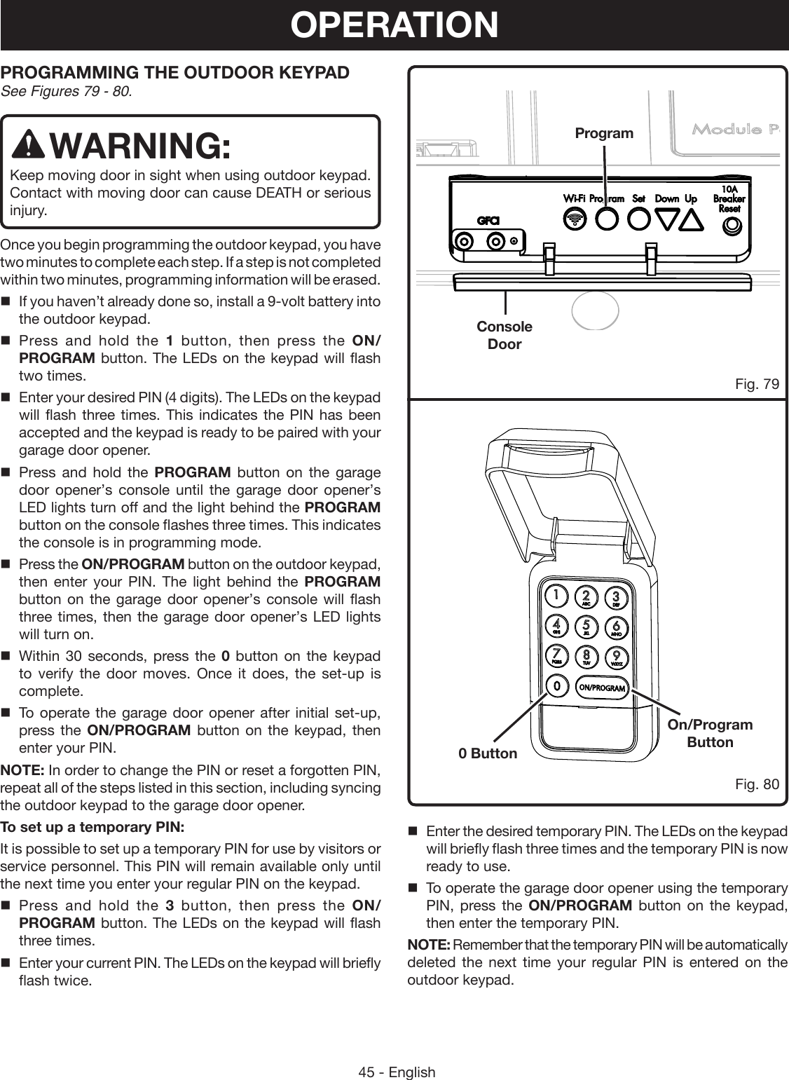
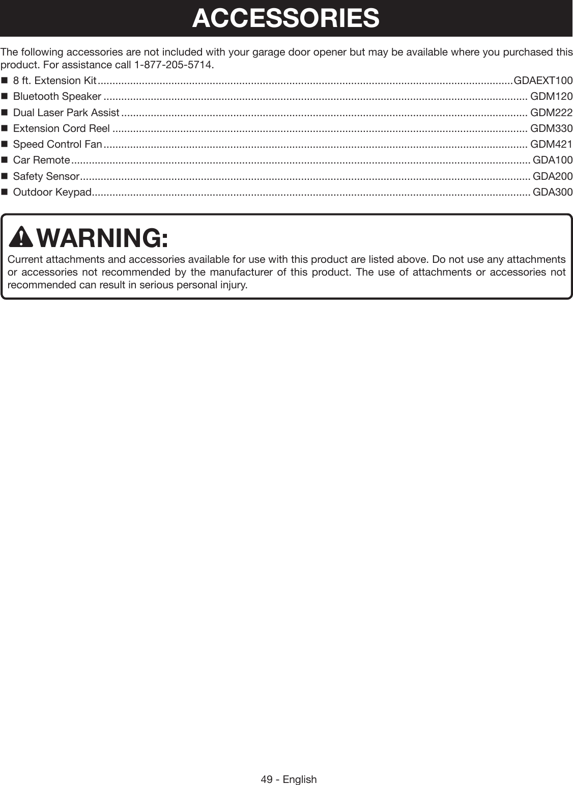
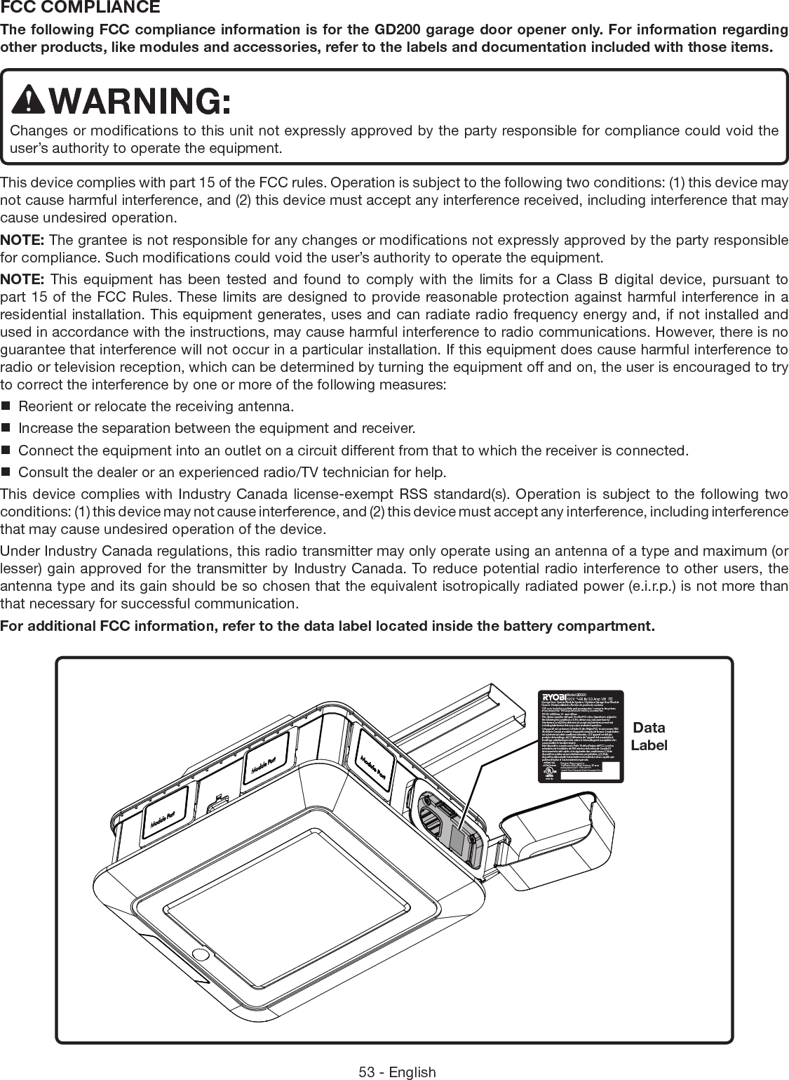
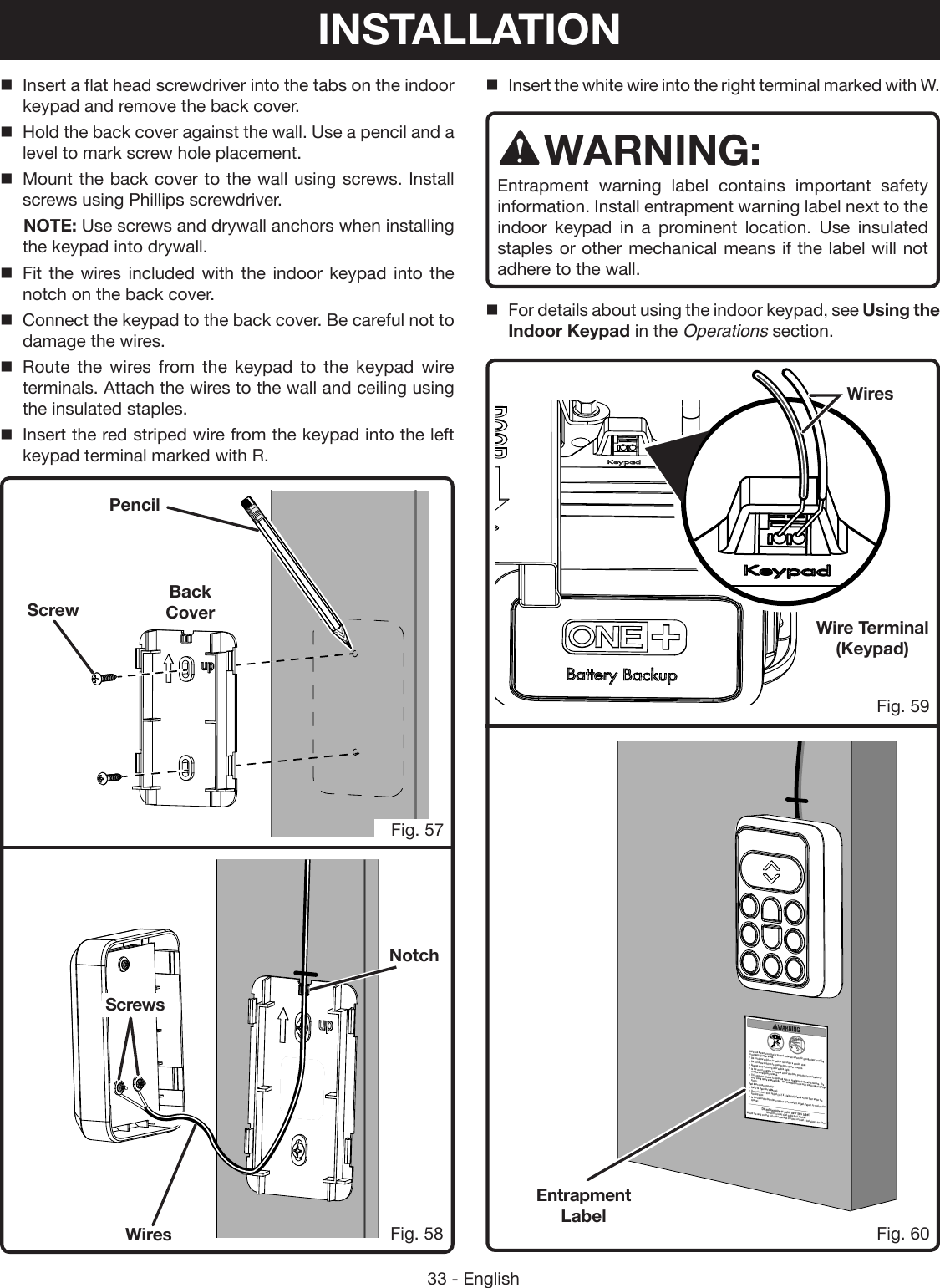
![32 - EnglishINSTALLING THE INDOOR KEYPAD See Figures 56 - 60.Locate the following items: Indoor Keypad Low Voltage Wire Insulated Staples Entrapment Label Screws (1 in., Phillips Hd.) [2] Drywall Anchors (2)WARNING:Do not use garage door opener if keypads or remotes do not start and stop the motor. An opener that cannot be controlled with a keypad or remote is dangerous, can result in death or serious personal injury, and must be repaired. WARNING:Make sure the keypad is mounted high enough to prevent unauthorized activation of the garage door opener. It should be placed at least five feet above the floor so that it is inaccessible to children. Unauthorized activation of the opener can result in death or serious personal injury. WARNING:Do not start or stop the garage door opener if there is a person or object in the path of the door, the door has not been properly balanced, or if you cannot see the doorway. Failure to follow these instructions can result in death or serious personal injury.WARNING:To avoid the risk of death, electric shock, or serious personal injury ensure that the garage door opener is unplugged and the battery pack is removed before wiring the keypad. WARNING:Connect the keypad using low voltage wires only to prevent the risk of electric shock or serious personal injury. Find desired location indoors and in sight of the garage door. NOTE: The keypad should be at least five feet above the floor so it is inaccessible to children.Fig. 55Twist the white wires from both sensors together and insert them into the left terminal marked with W.For alignment instructions, see Aligning The Safety Sensors in the Operations section.Wire Terminal (Door Sensor)Wires (White)Wires (Striped)“W” “G”TabBack CoverFig. 56INSTALLATION](https://usermanual.wiki/One-World-Technologies/GD200.Users-Manual-2/User-Guide-2906780-Page-4.png)
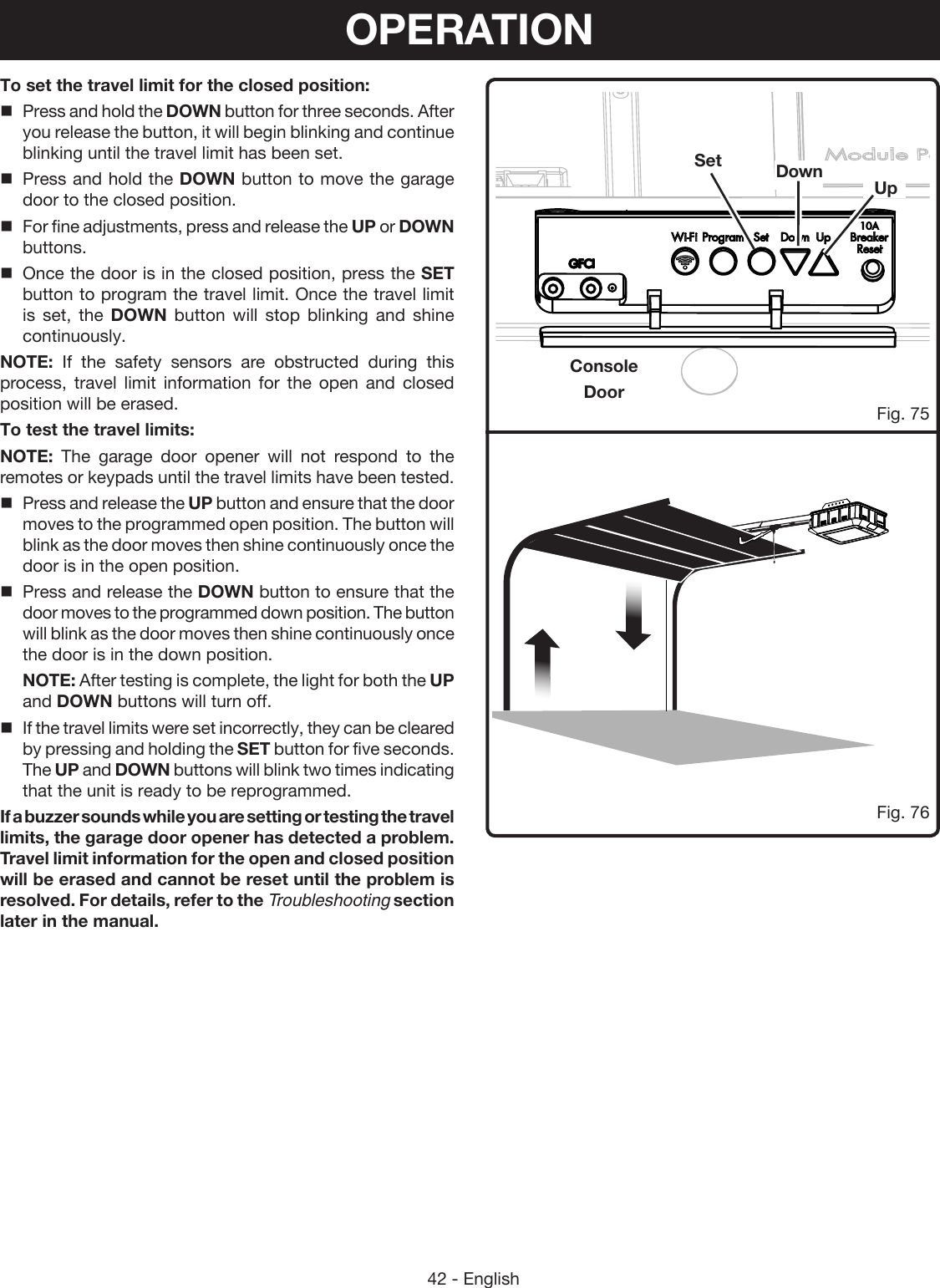
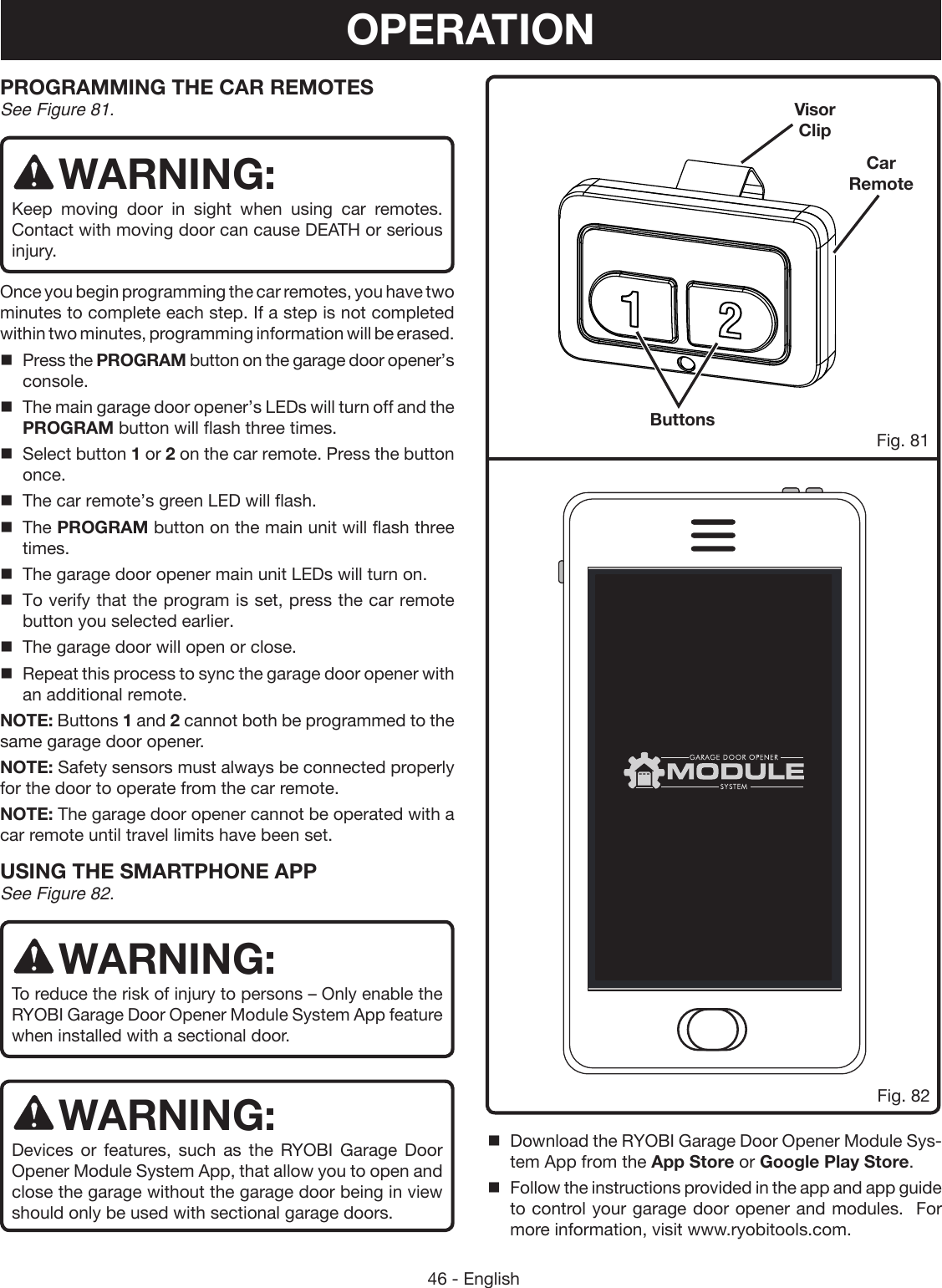
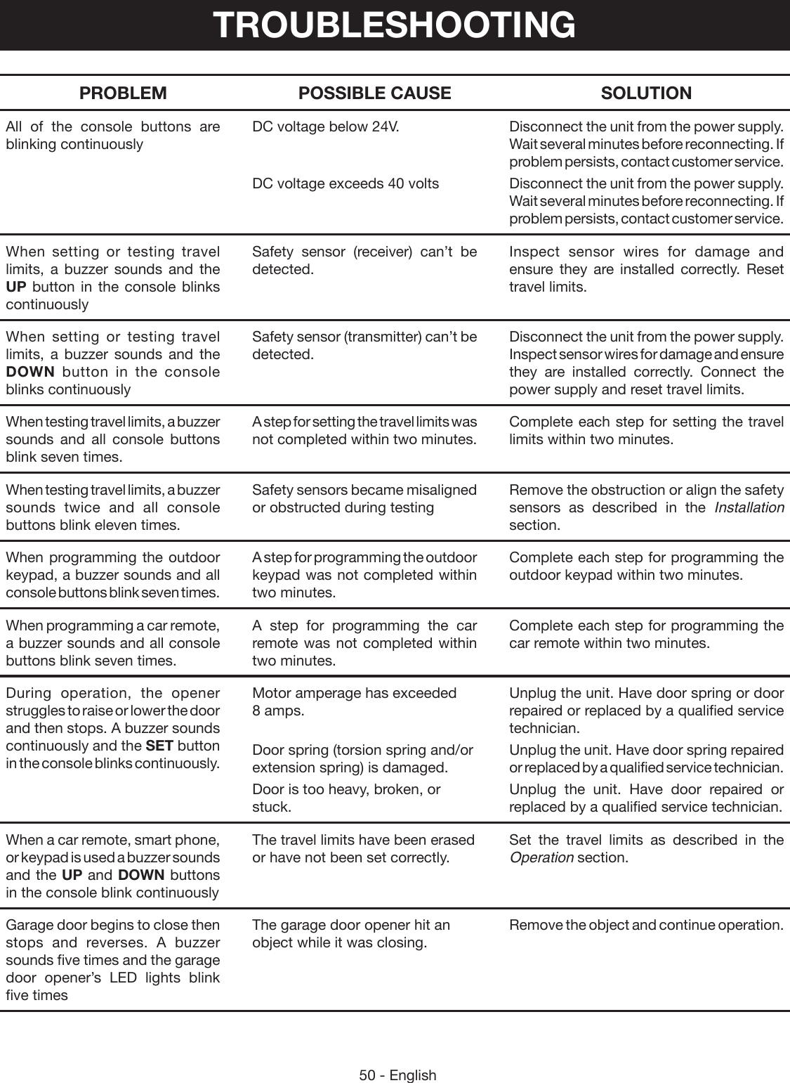
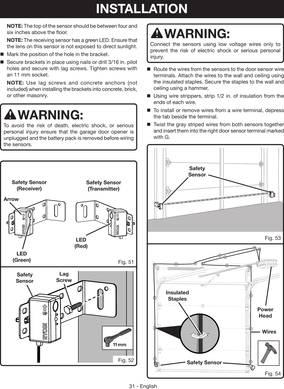
![34 - EnglishTop ScrewBottom ScrewINSTALLING THE OUTDOOR KEYPAD See Figures 61 - 63.Locate the following items: Outdoor Keypad Screws (1 in., Phillips Hd.) [2] Drywall Anchors (2)WARNING:Do not use garage door opener if keypads or remotes do not start and stop the motor. An opener that cannot be controlled with a keypad or remote is dangerous, can result in death or serious personal injury, and must be repaired. WARNING:Make sure the keypad is mounted high enough to prevent unauthorized activation of the garage door opener. It should be placed at least five feet above the floor so that it is inaccessible to children. Unauthorized activation of the opener can result in death or serious personal injury. WARNING:Do not start or stop the garage door opener if there is a person or object in the path of the door, the door has not been properly balanced, or if you cannot see the doorway. Failure to follow these instructions can result in death or serious personal injury.NOTE: For convenience, we recommend you program the outdoor keypad before installing. See Programming the Outdoor Keypad in the Operations section.Find desired location outdoors and in sight of the garage door. NOTE: The keypad should be at least five feet above the floor so it is inaccessible to children.Use a pencil to mark screw hole placement and install top screw. NOTE: Use screws and drywall anchors when installing the keypad into drywall. Place the wide portion of the key hole over the head of the top screw.Slide the keypad down until the top screw is inside the narrow portion of the key hole.Remove the battery cover and 9-volt battery.Use a level to be sure the keypad is in a vertical position, then install bottom screw into the screw hole.Fig. 62Fig. 63Key HoleBattery CoverBatteryScrewdriverPencilOutdoor KeypadFig. 61Screw HoleInstall 9-volt battery.Replace battery cover.For programming instructions, see Programming the Outdoor Keypad in the Operations section.INSTALLATION](https://usermanual.wiki/One-World-Technologies/GD200.Users-Manual-2/User-Guide-2906780-Page-6.png)