Olympus Medical Systems RU2020 Endoscope Reprocessor User Manual GT9883 0004 fm10
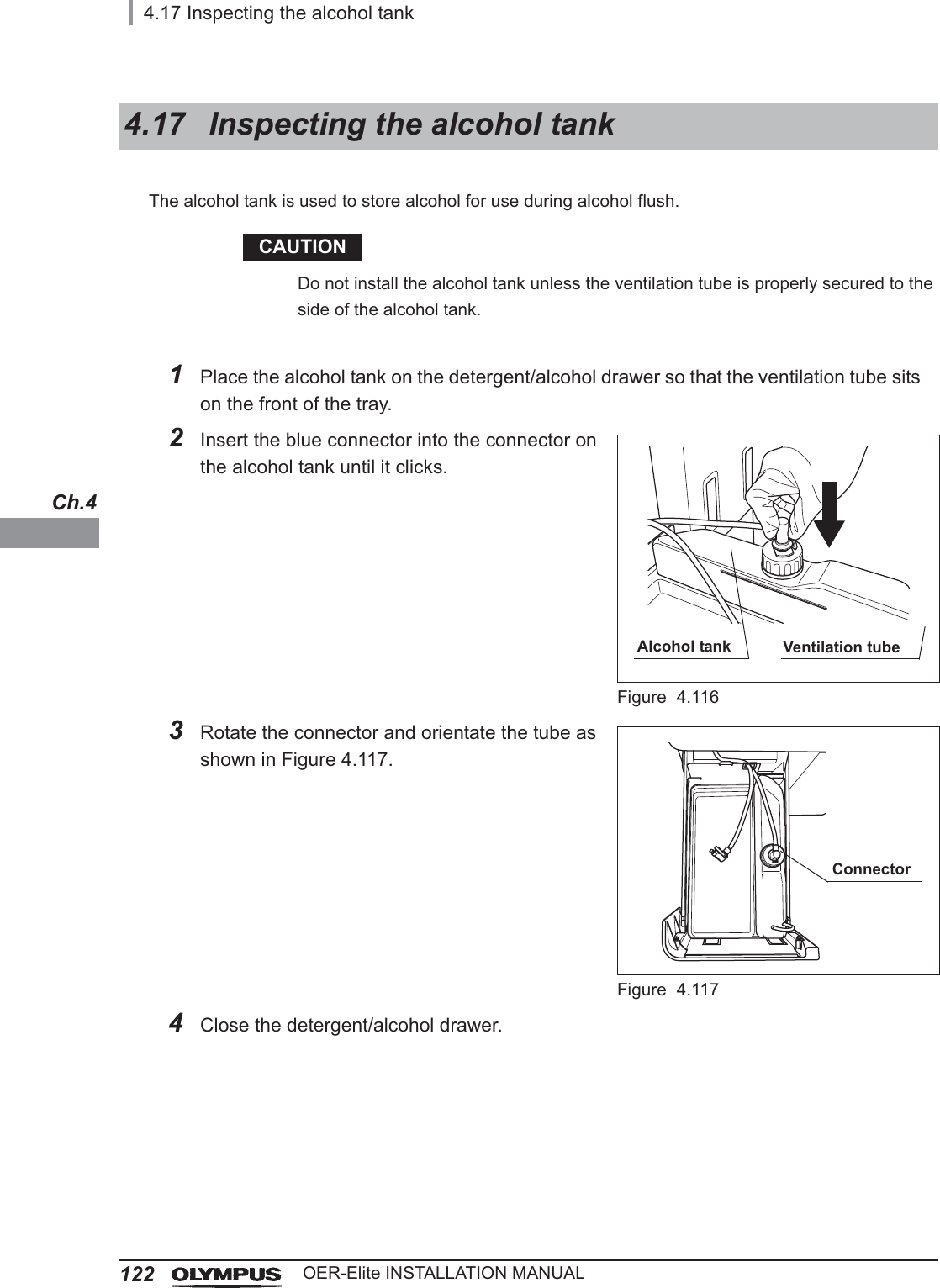
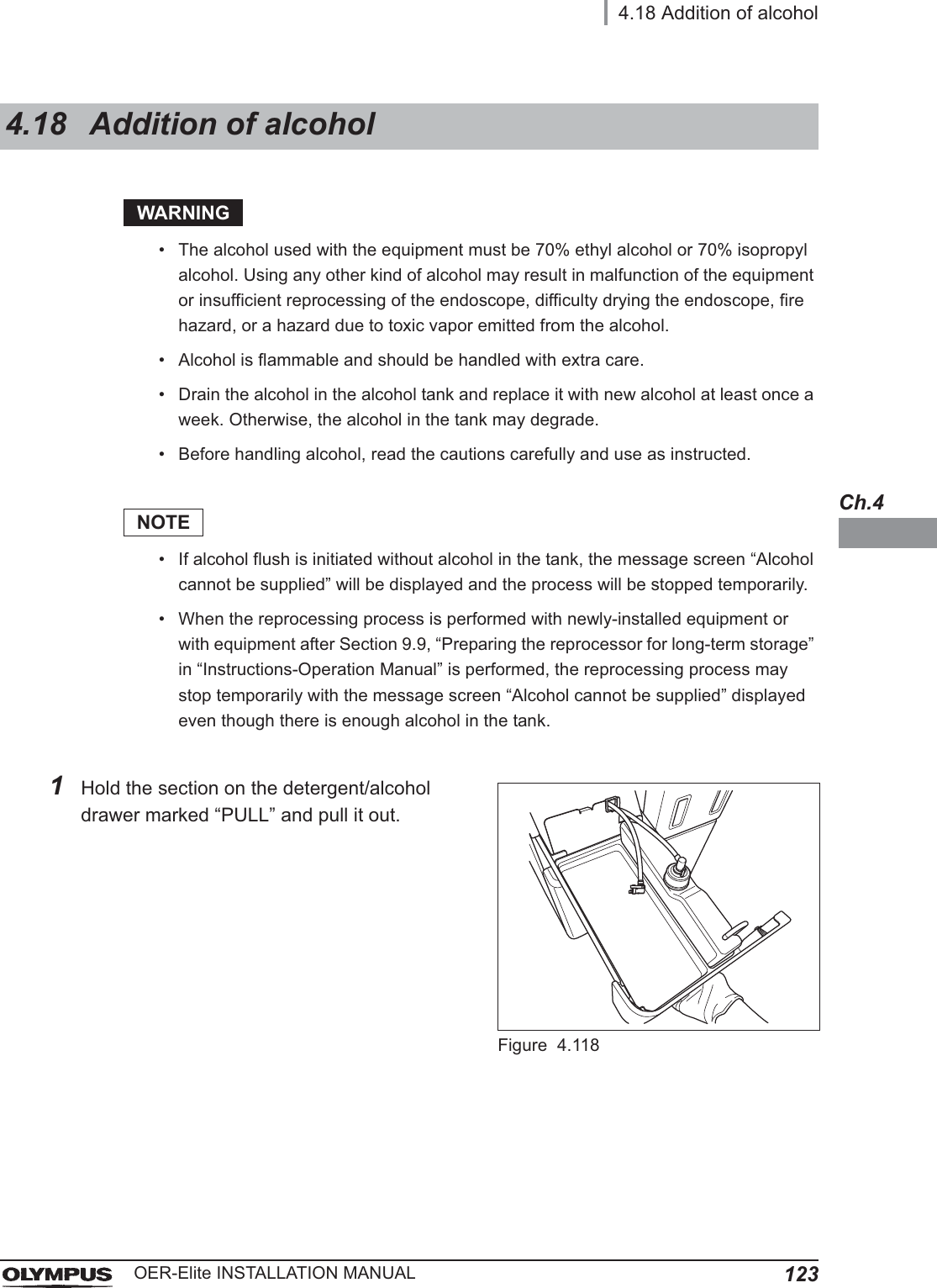
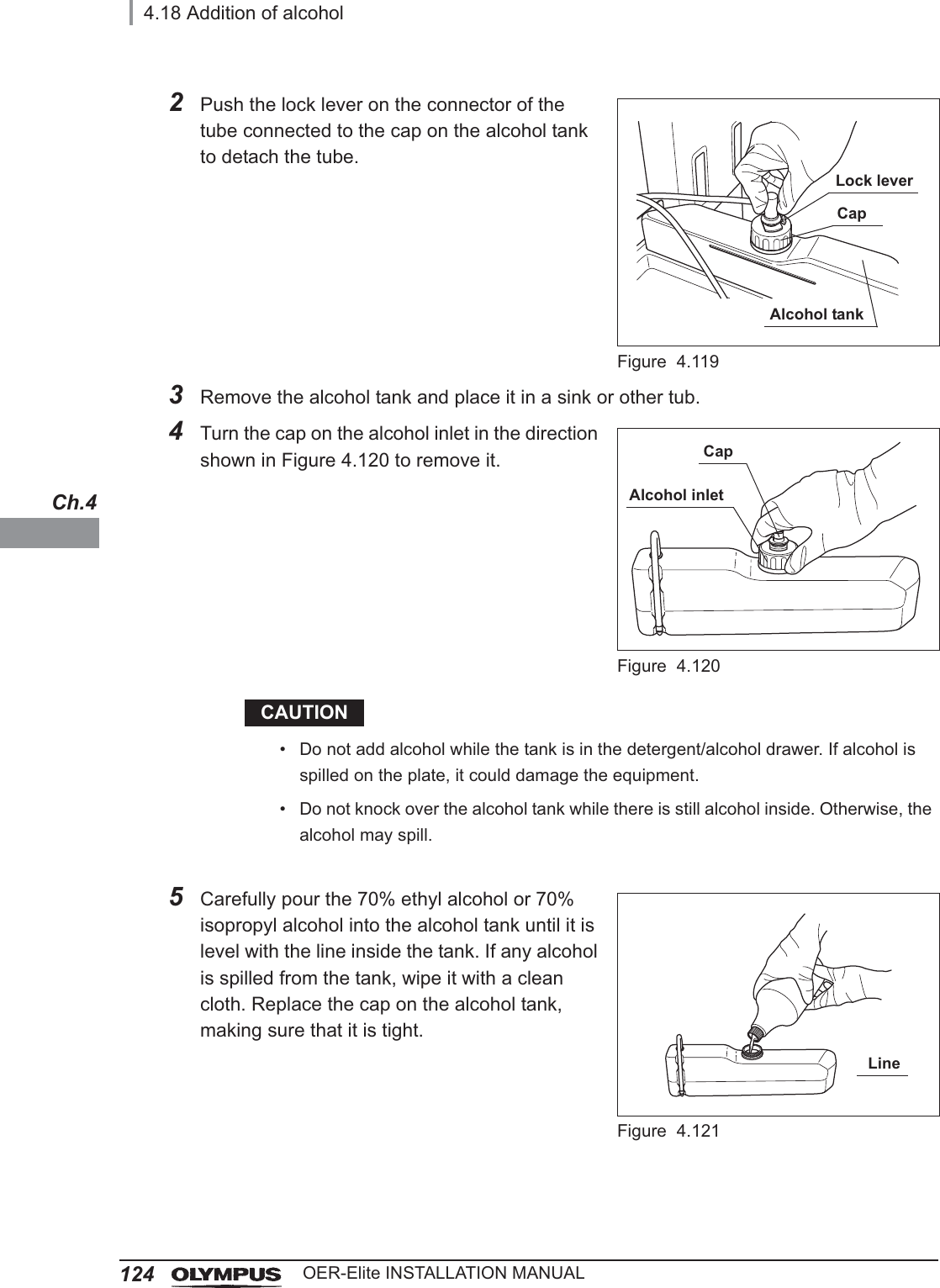
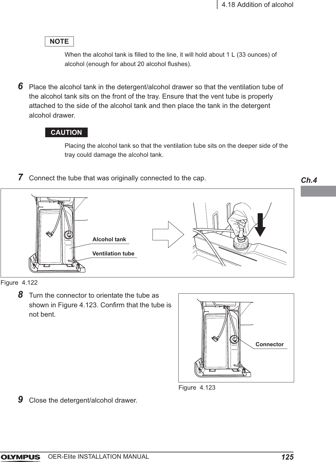
Olympus Medical Systems Corp. Endoscope Reprocessor GT9883 0004 fm10
UserManual.wiki
>
Olympus Medical Systems
>
RU2020 User Manual
>
Installation Manual 2
Contents
1.
Operation Manual 1
2.
Operation Manual 2
3.
Operation Manual 3
4.
Operation Manual 4
5.
Operation Manual 5
6.
Installation Manual 1
7.
Installation Manual 2
Installation Manual 2
Navigation menu
Upload a User Manual
Namespaces
Wiki Guide
HTML
PDF
Info
Views
User Manual
Discussion / Help
Navigation
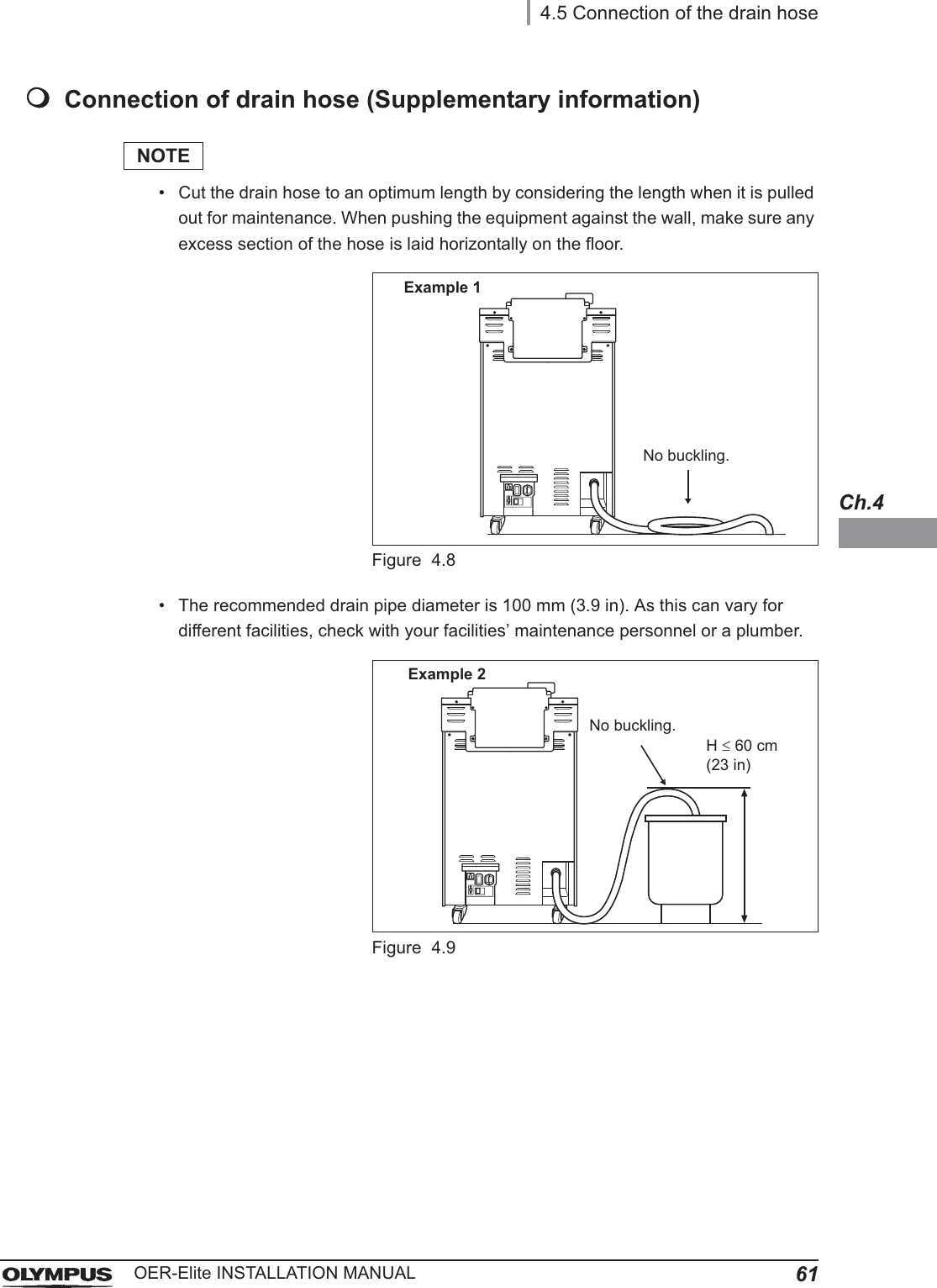
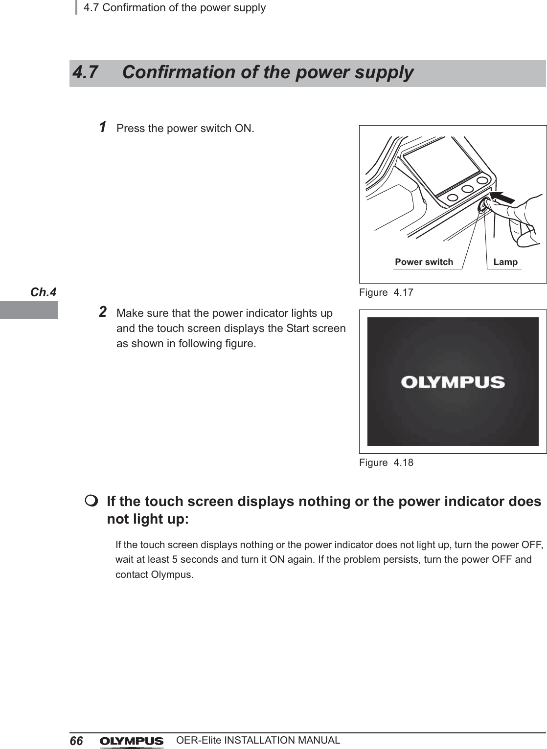
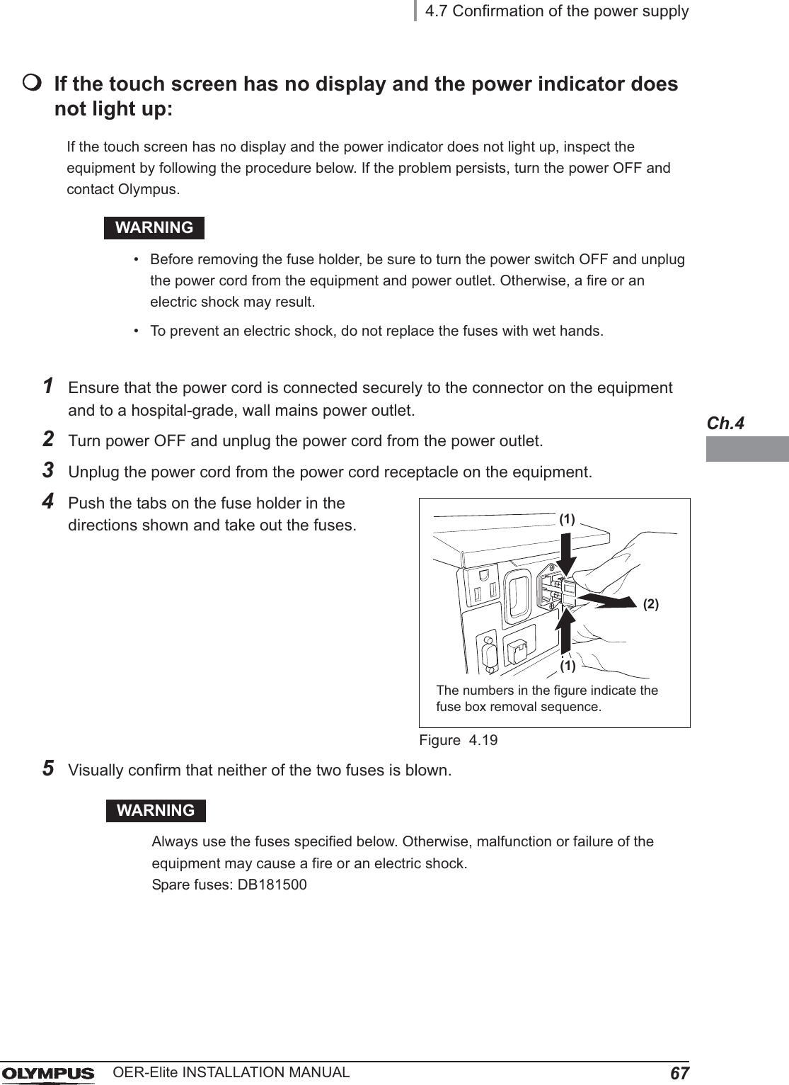
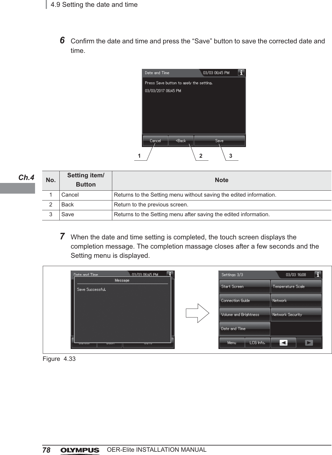
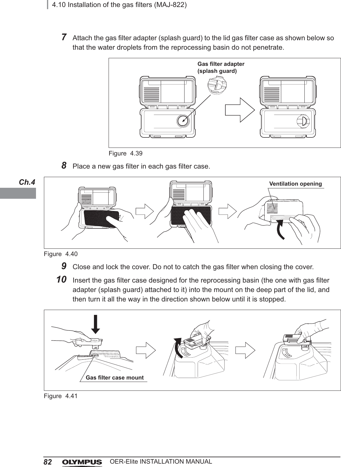
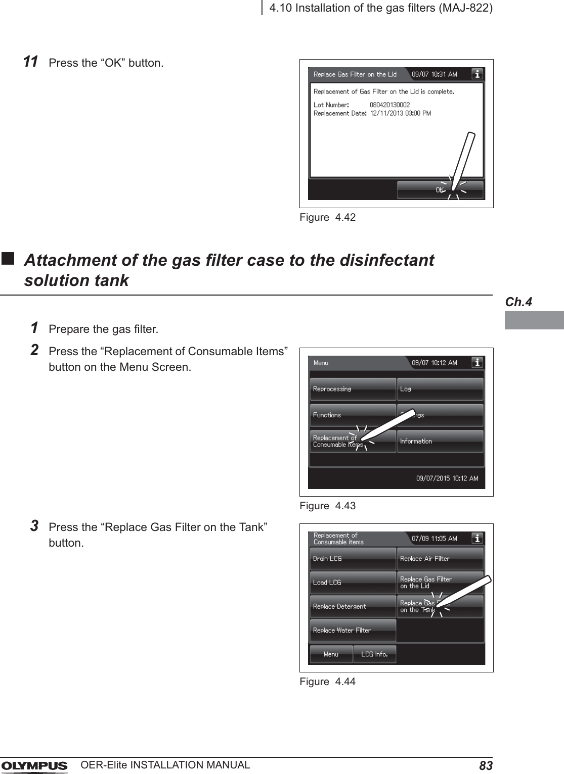
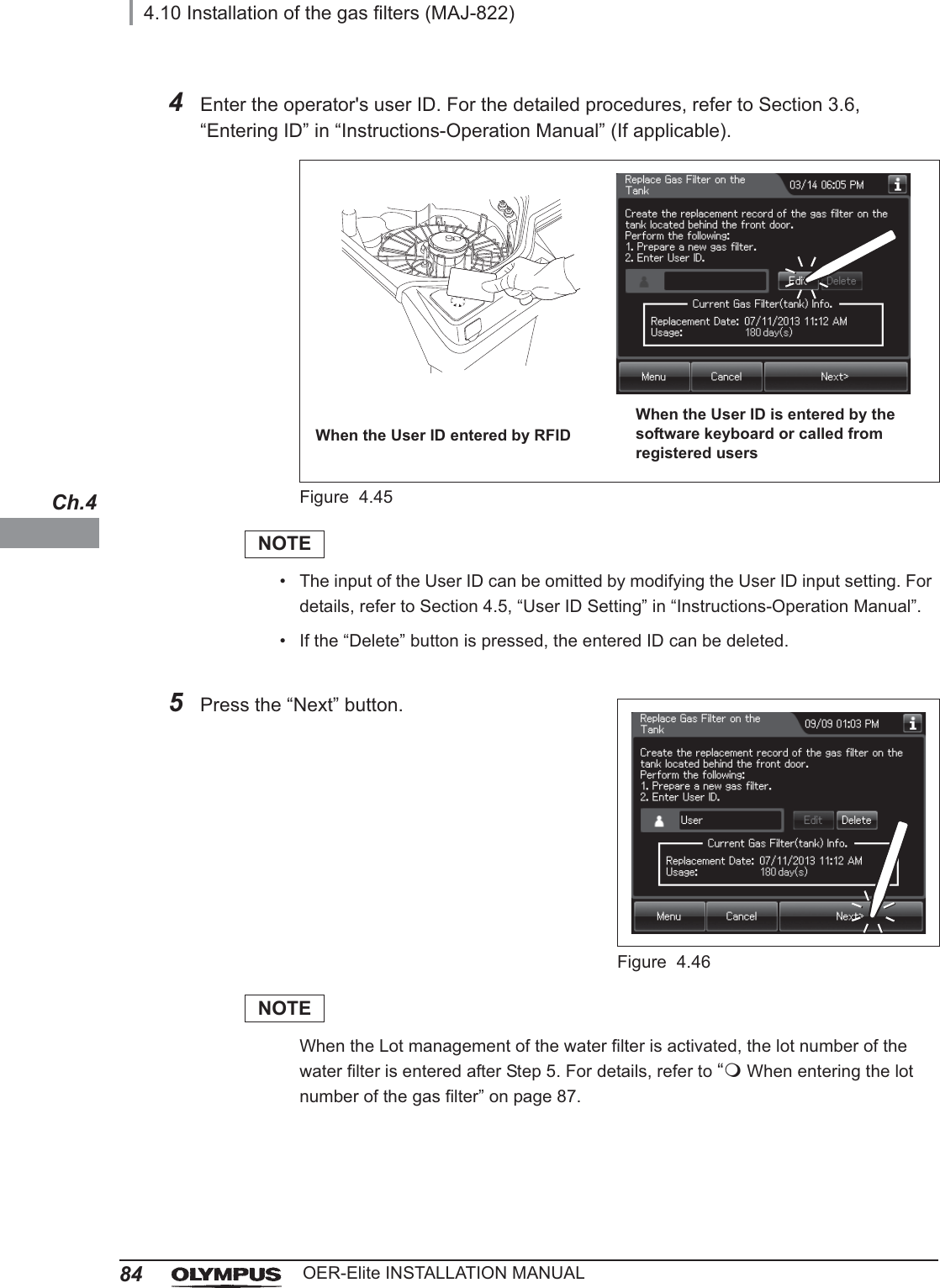
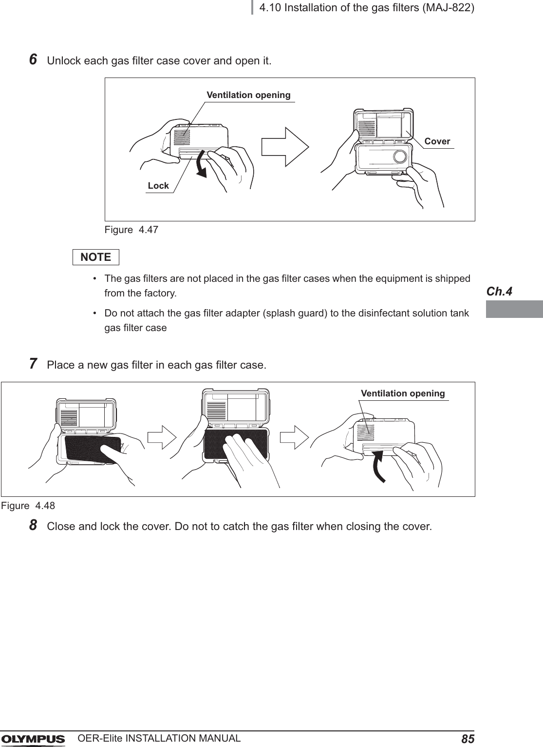
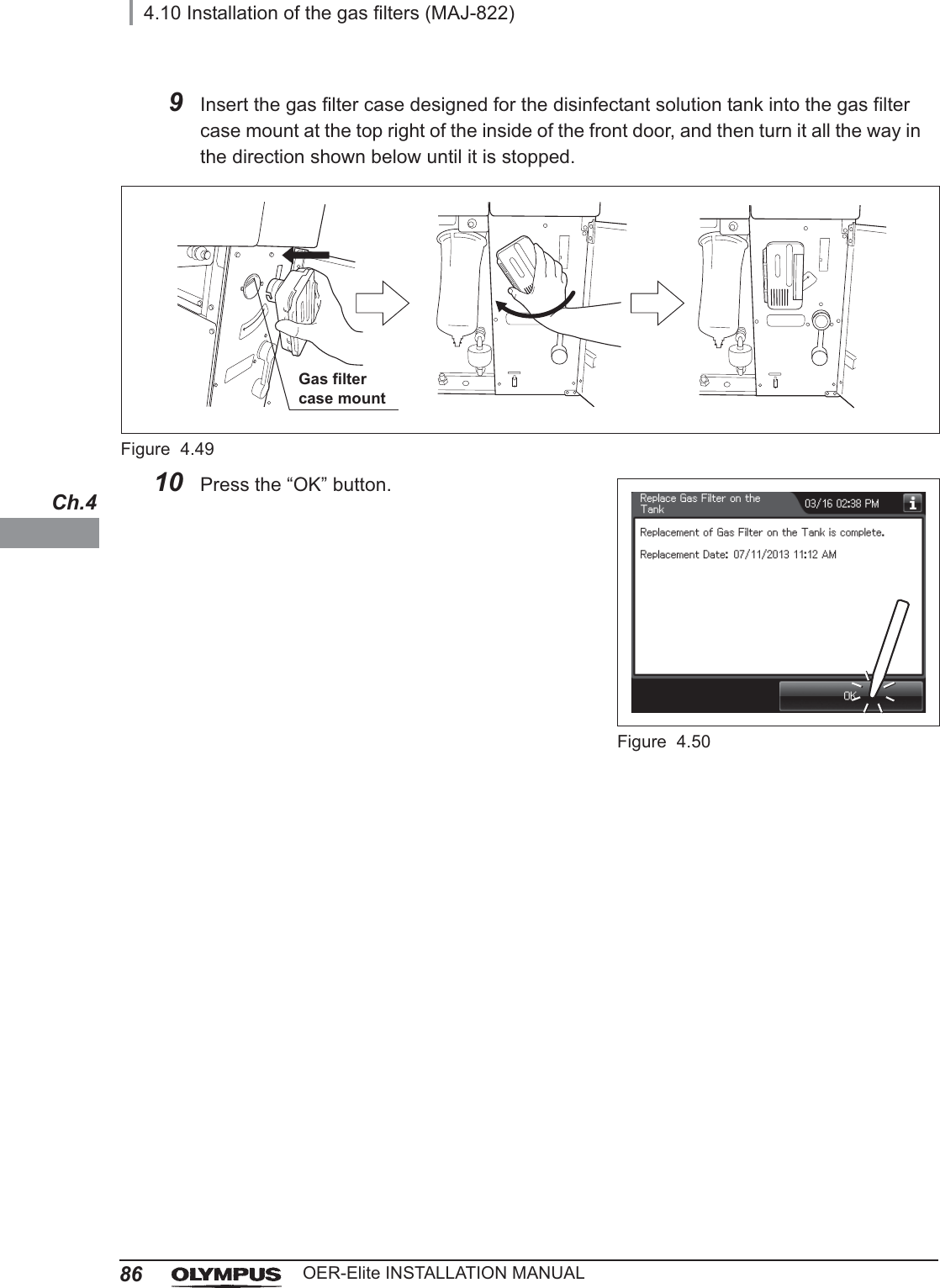
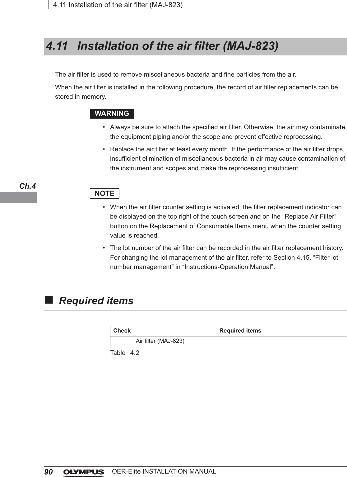
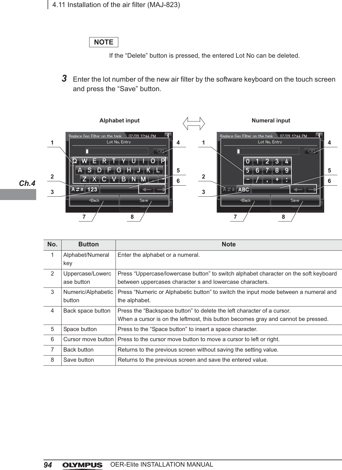
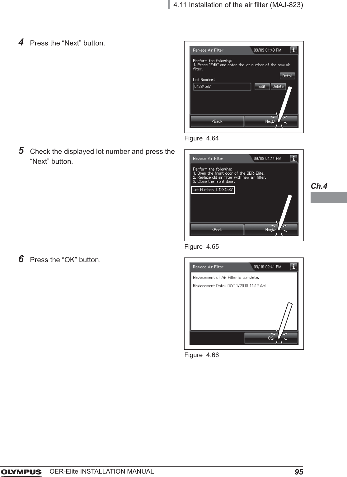
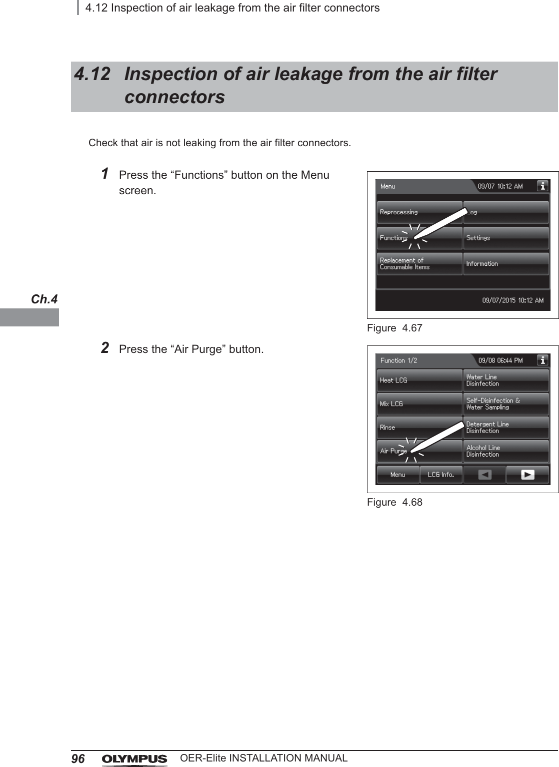
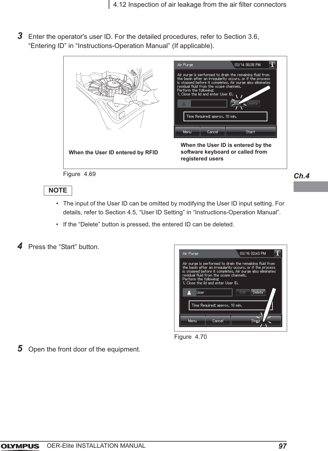
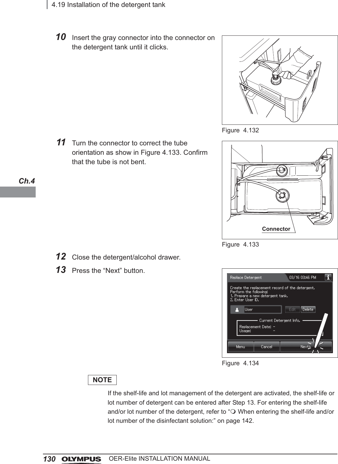
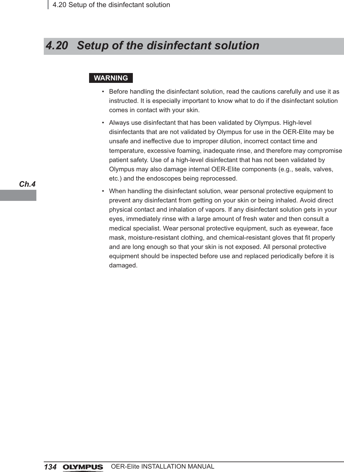
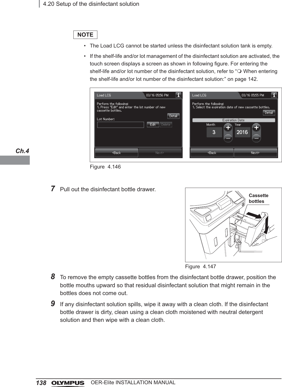
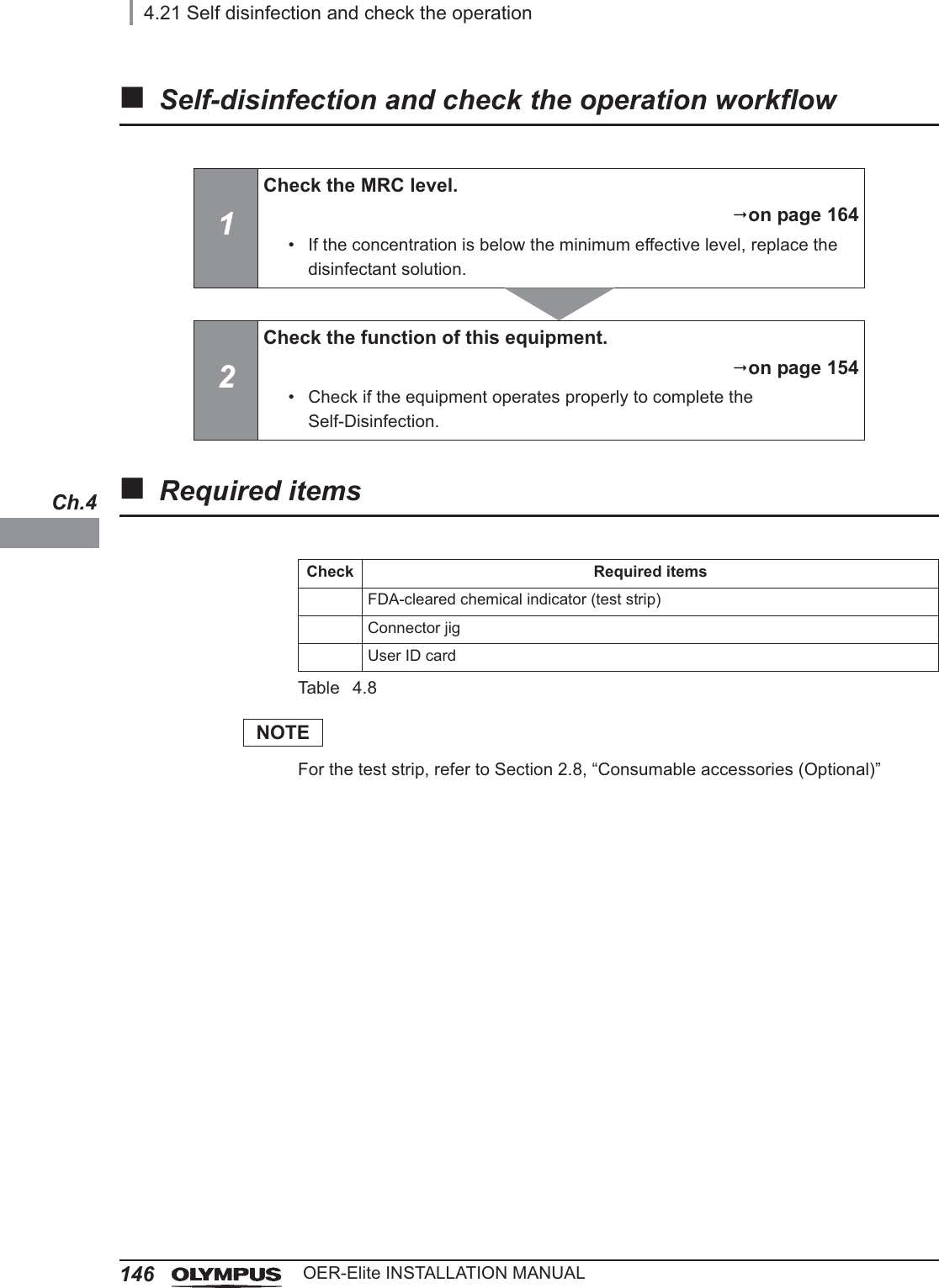
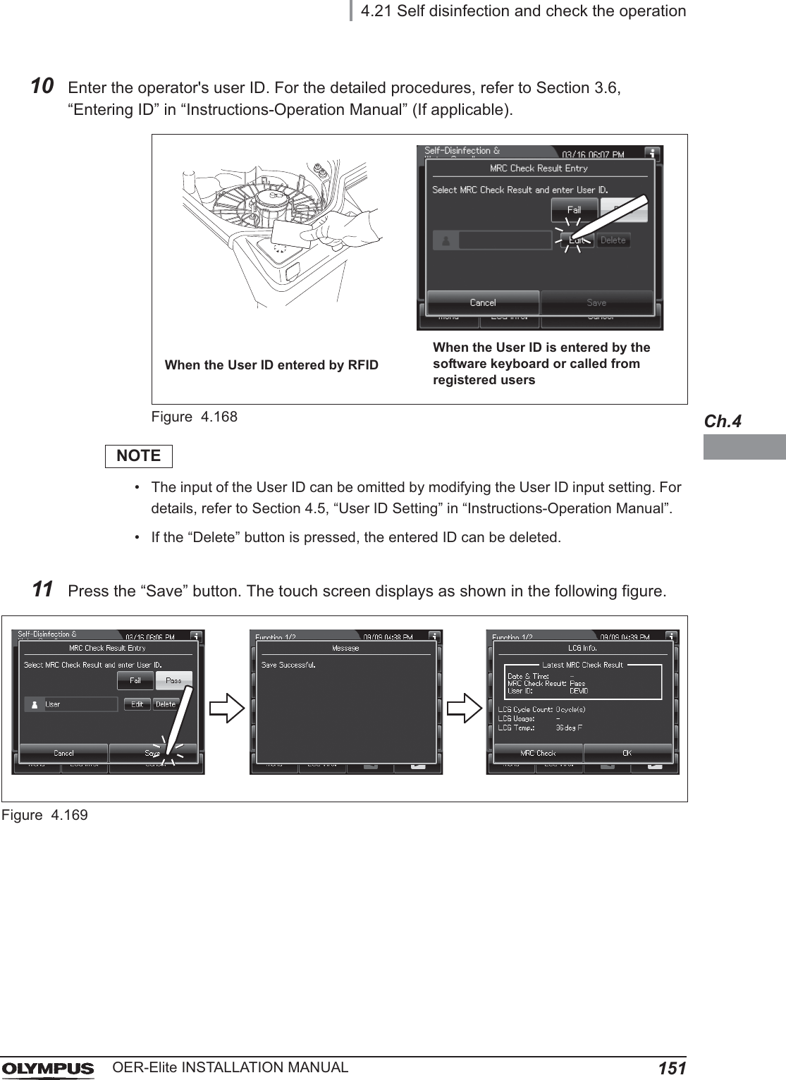
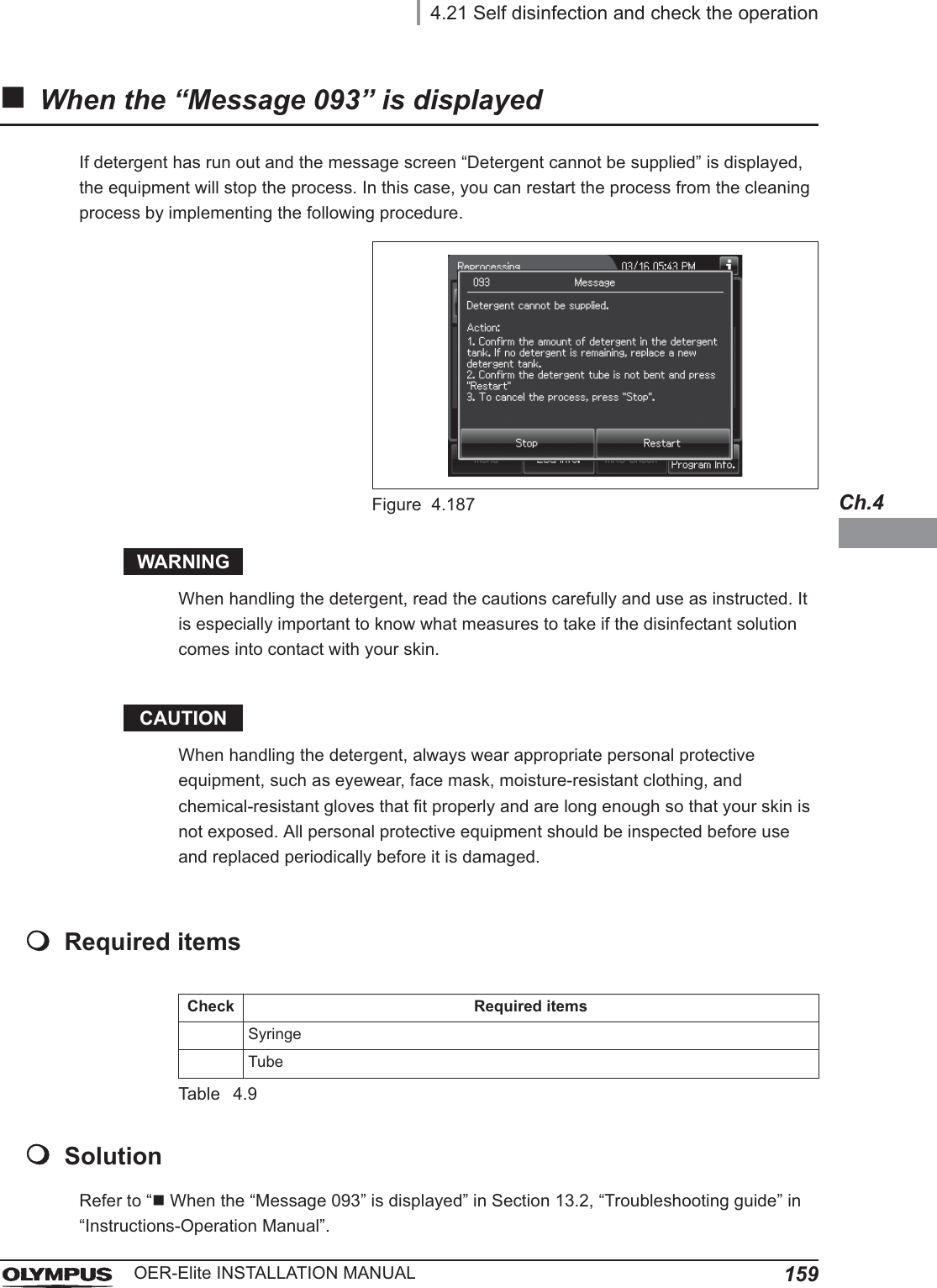
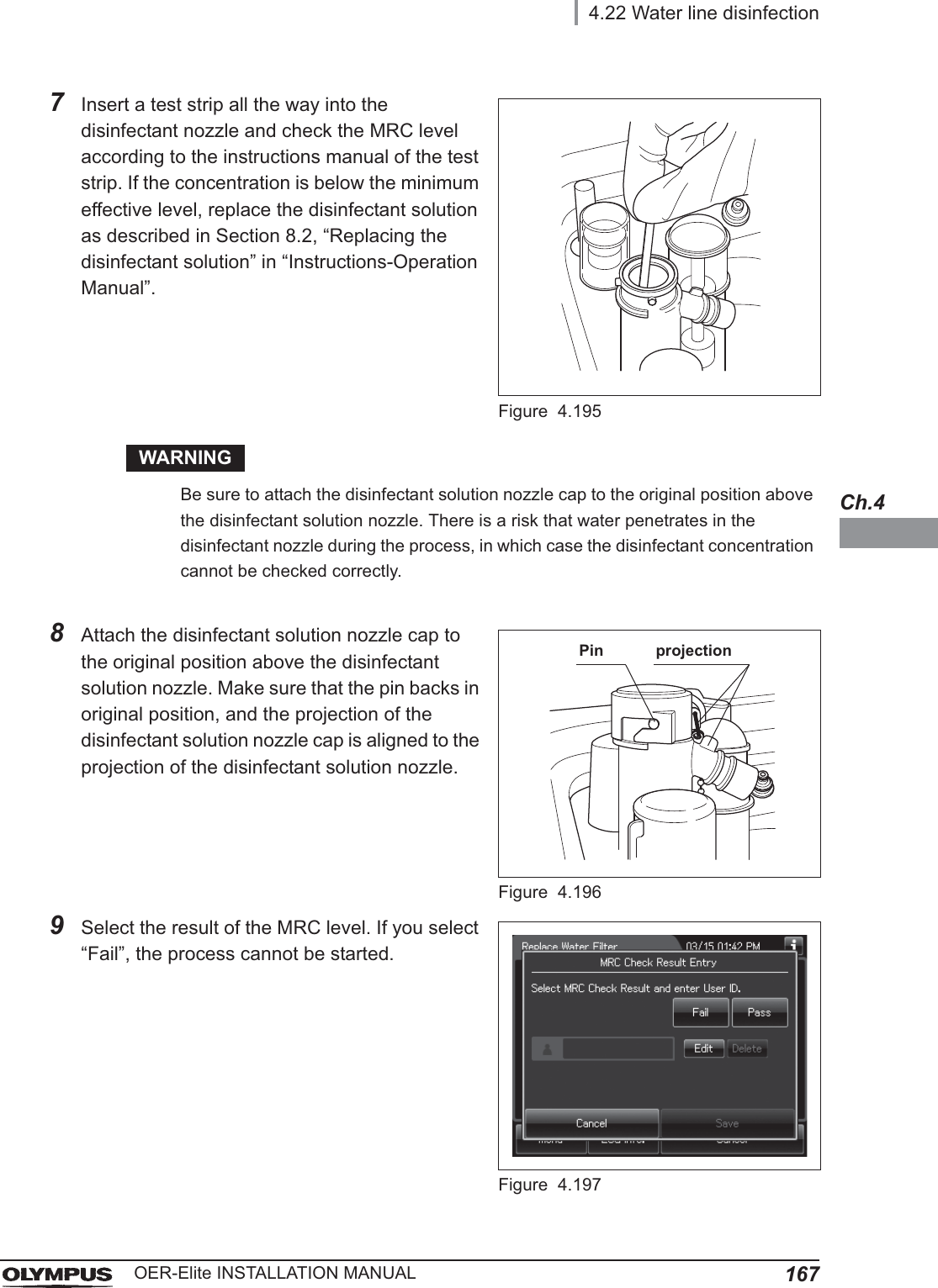
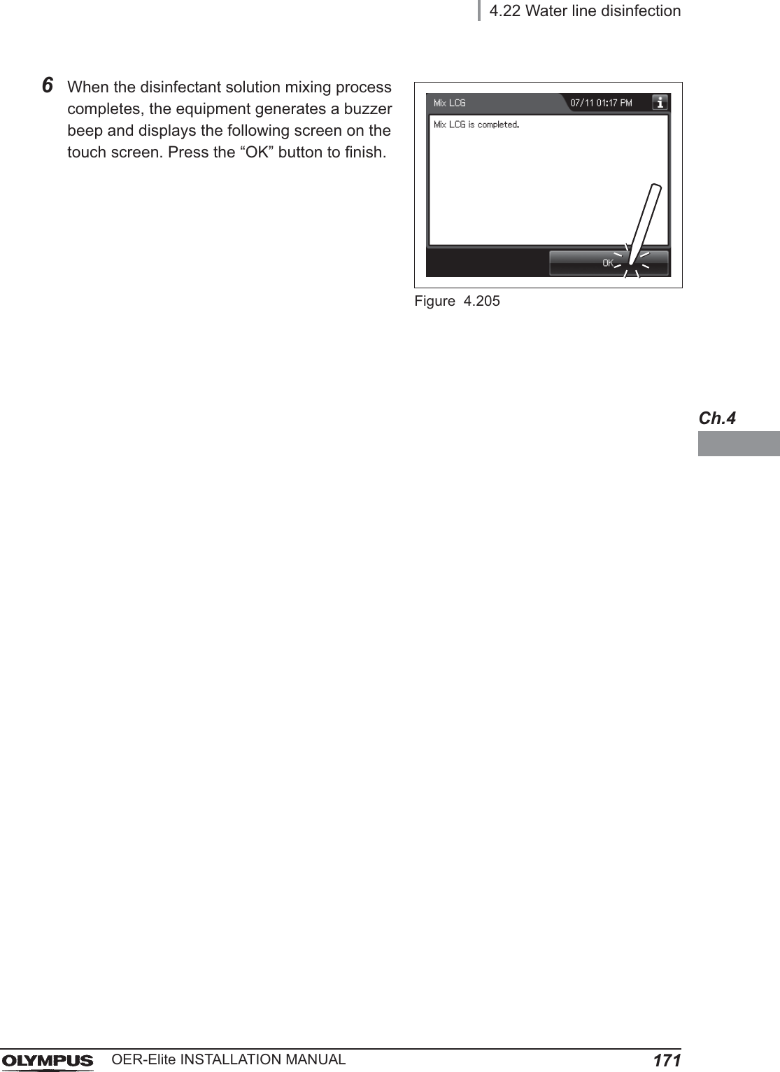
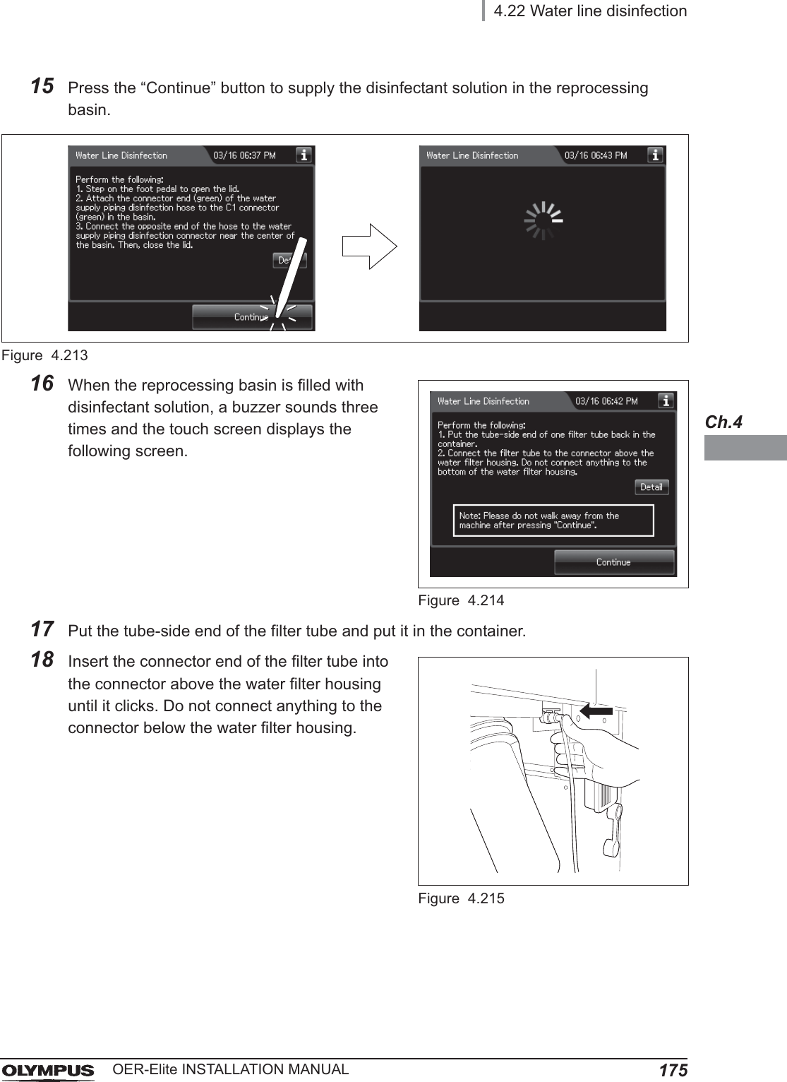
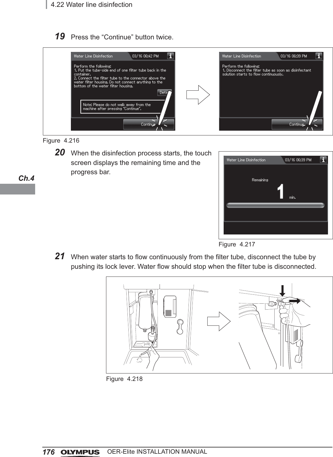
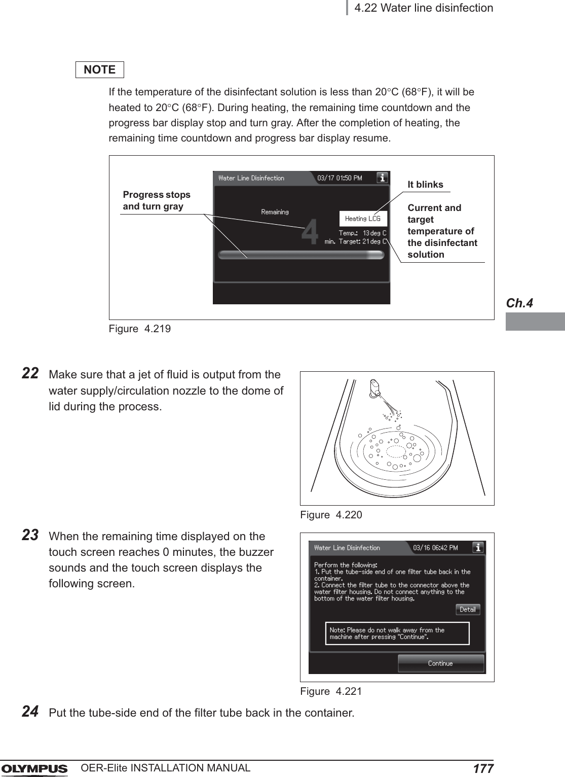
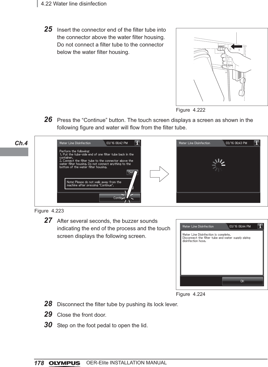
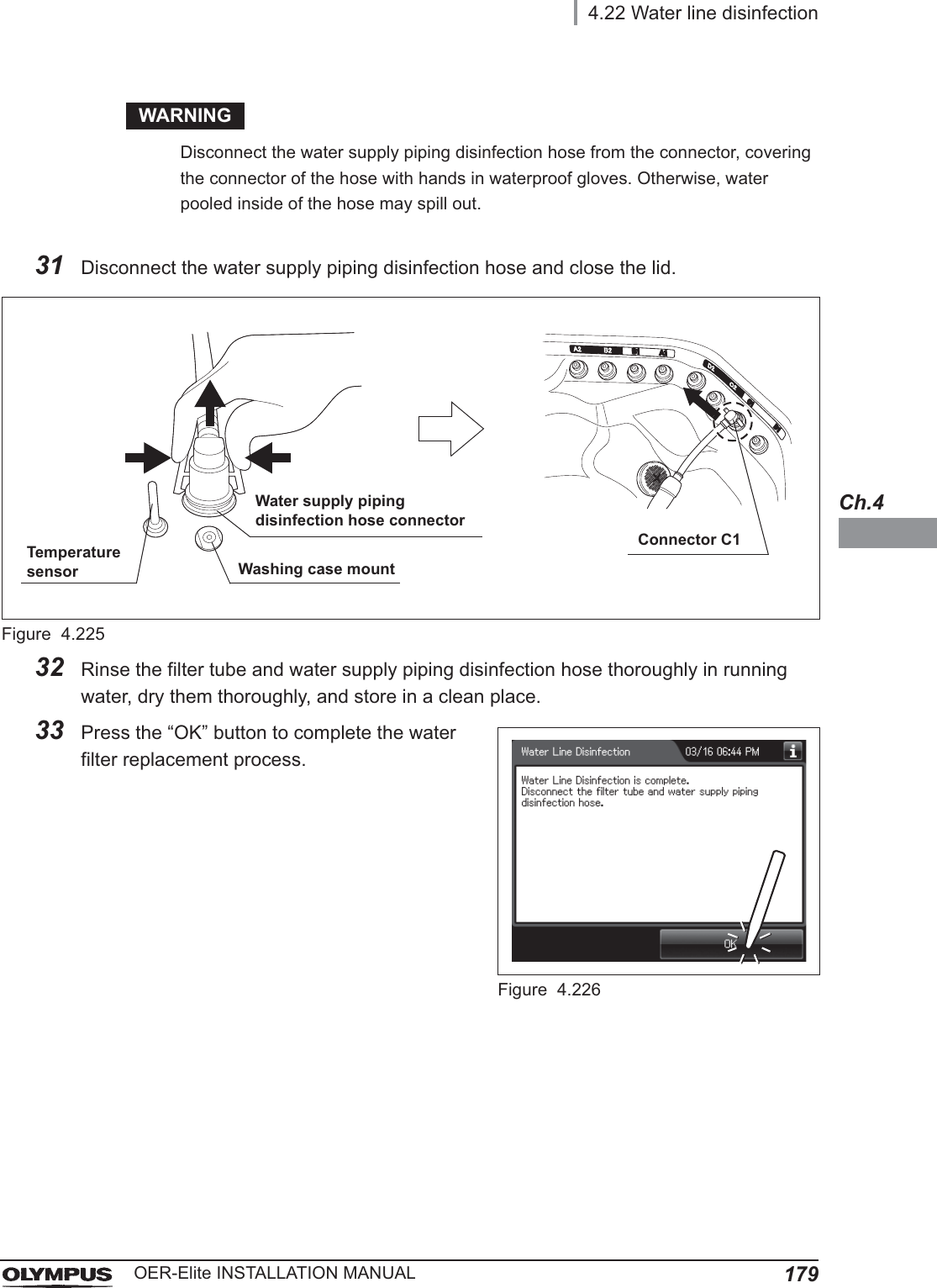
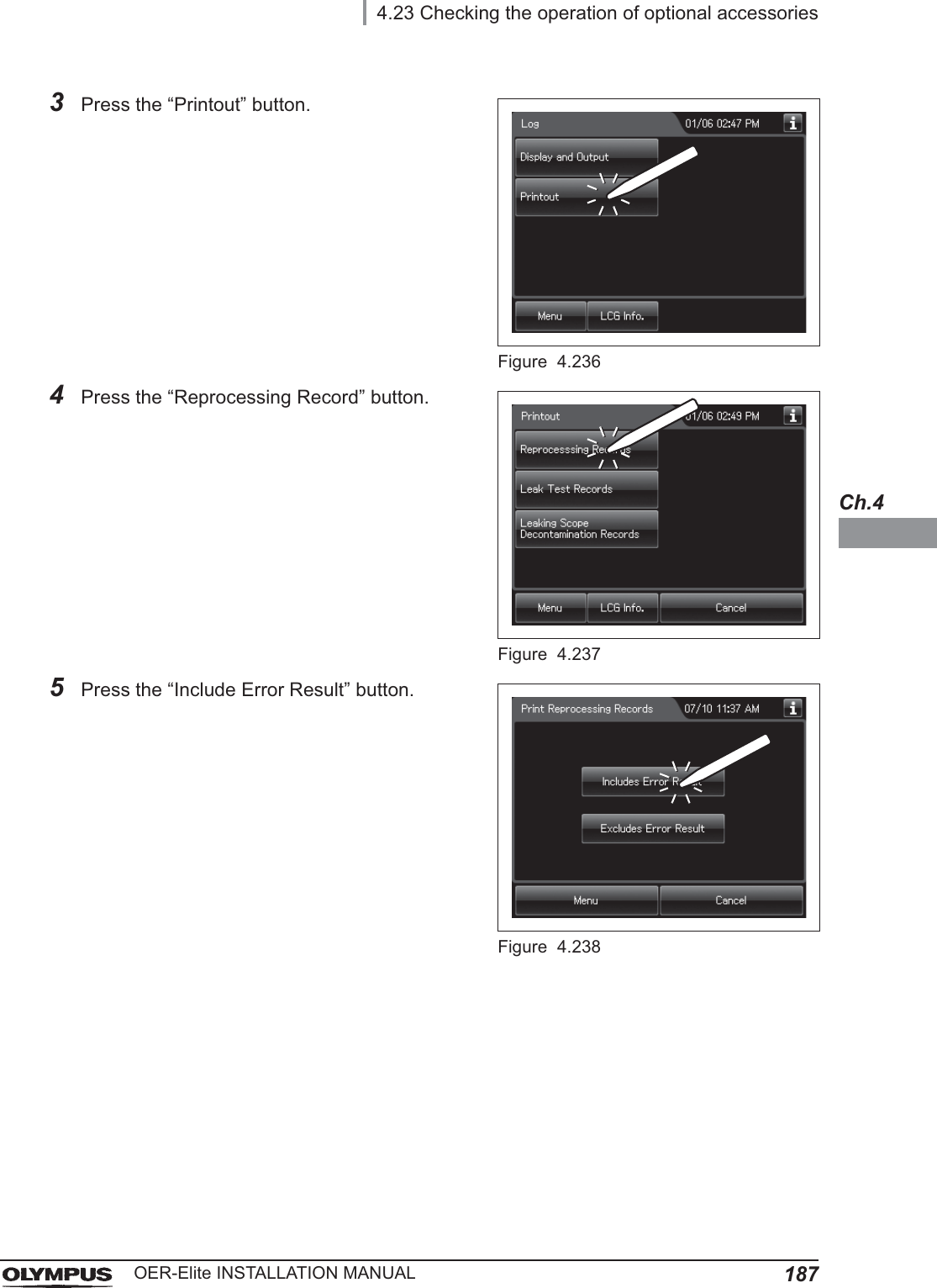
![984.12 Inspection of air leakage from the air filter connectorsOER-Elite INSTALLATION MANUALCh.46When air purge has started, touch the air filter connectors to ensure that air is not leaking out. Also, ensure that the connectors do not produce a whistling sound, which would mean there is an air leak.Figure 4.717Press the “Stop” button on the touch screen to end Air Purge. If an air Leak is detected, reinstall the air filter as described in refer to “Replacing the air filter” in Section 8.5, “Replacing the air filter (MAJ-823)” in “Instructions-Operation Manual”.8The touch screen displays the error code [E000]. Press the “OK” button repeatedly until the error screen is closed.Figure 4.72ConnectorConnector](https://usermanual.wiki/Olympus-Medical-Systems/RU2020.Installation-Manual-2/User-Guide-3575696-Page-38.png)
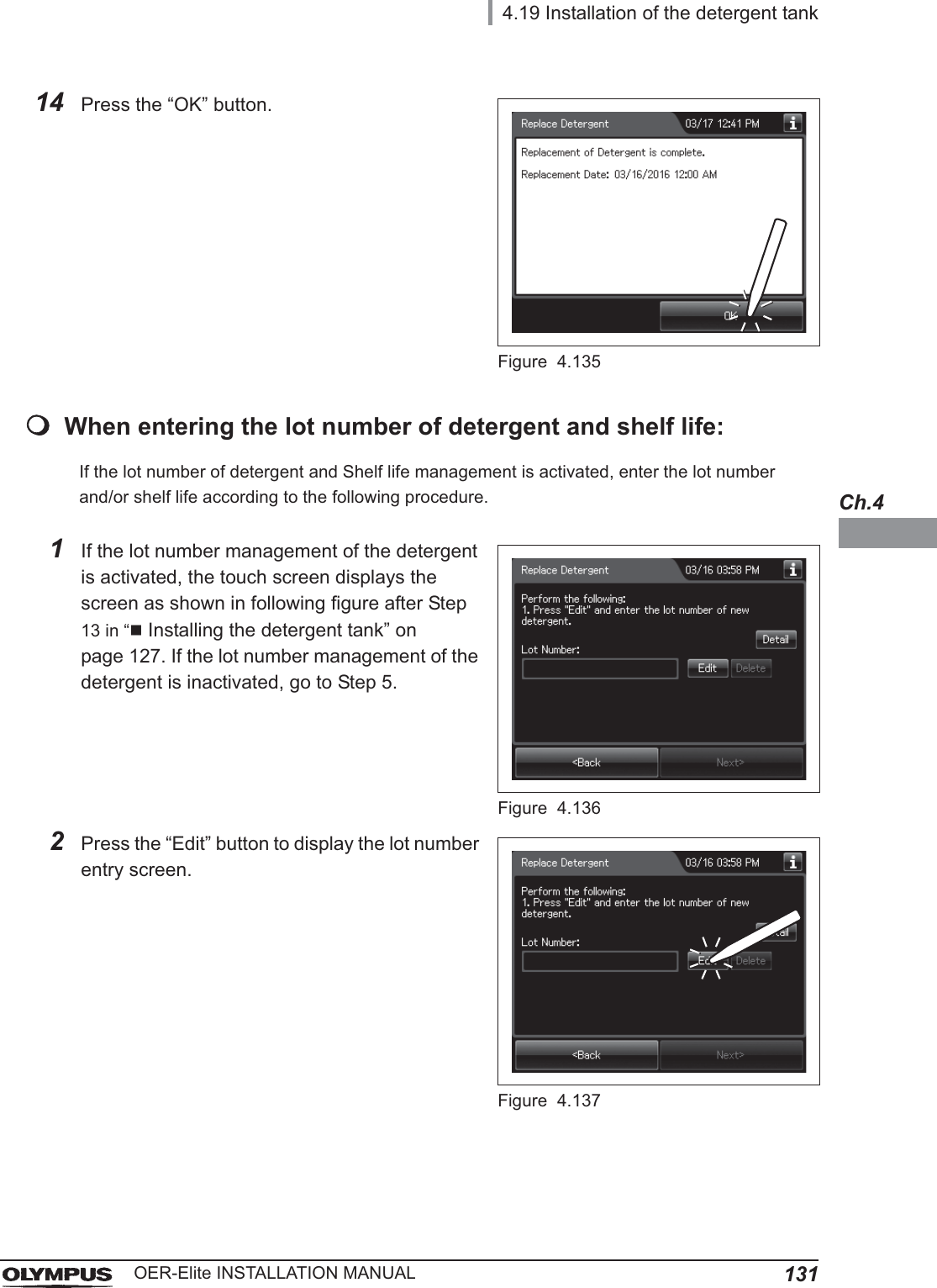
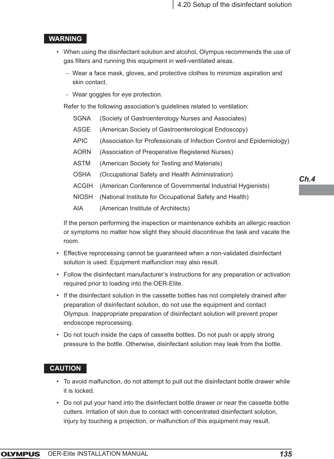
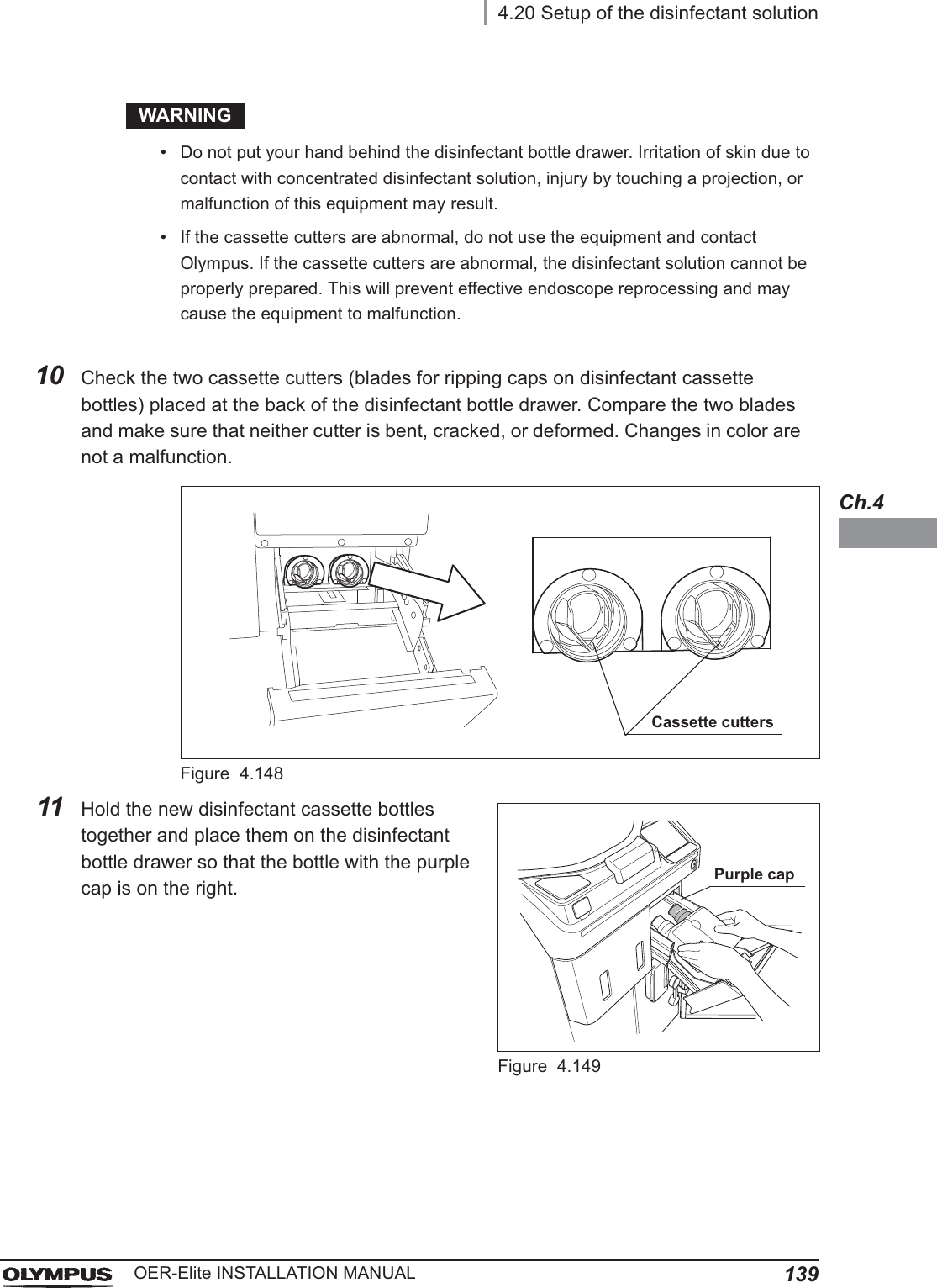
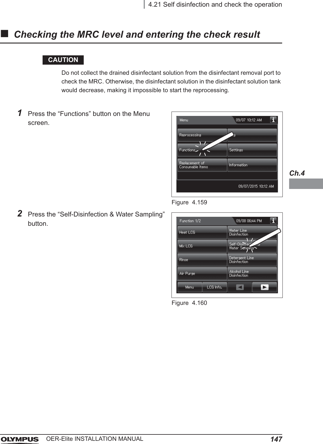
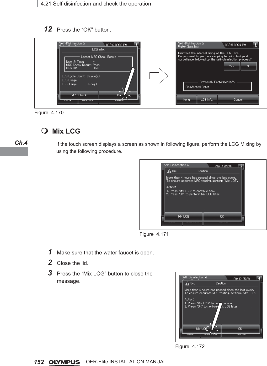
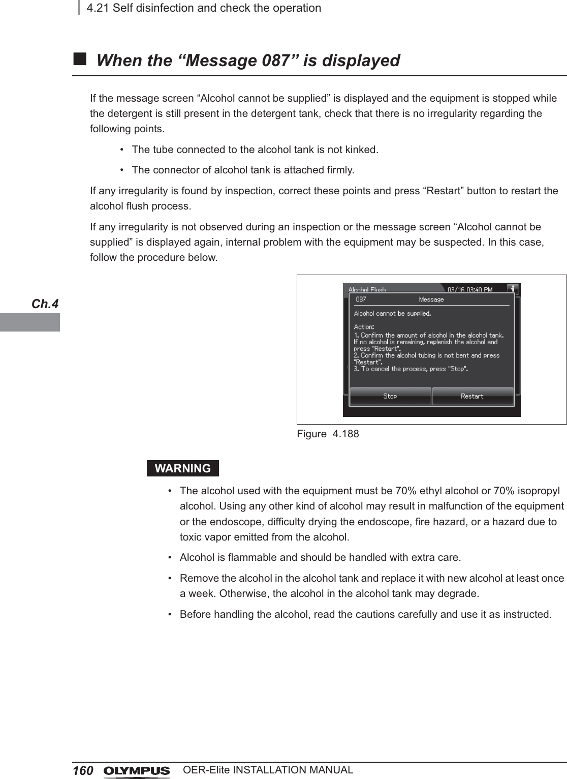
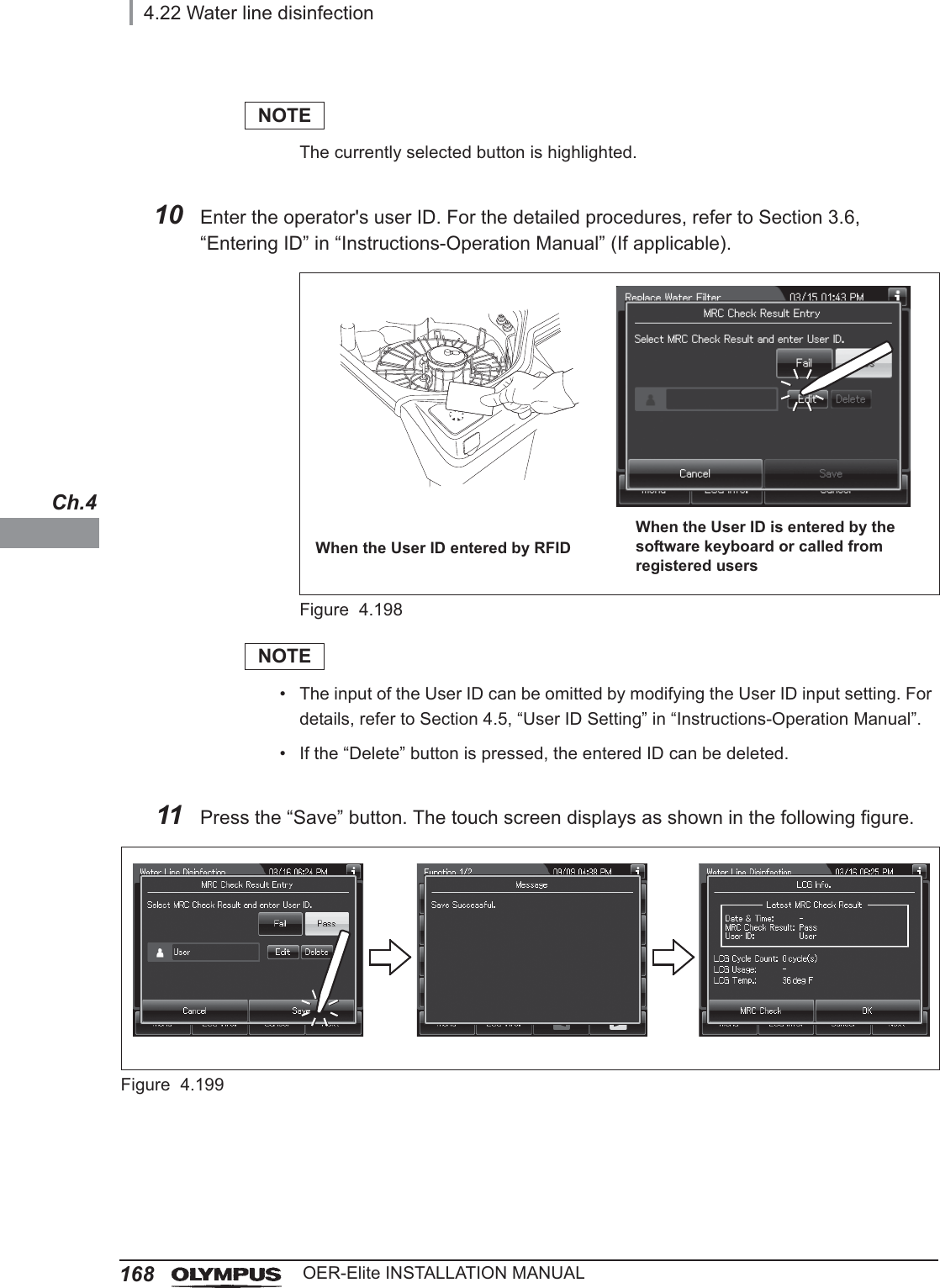
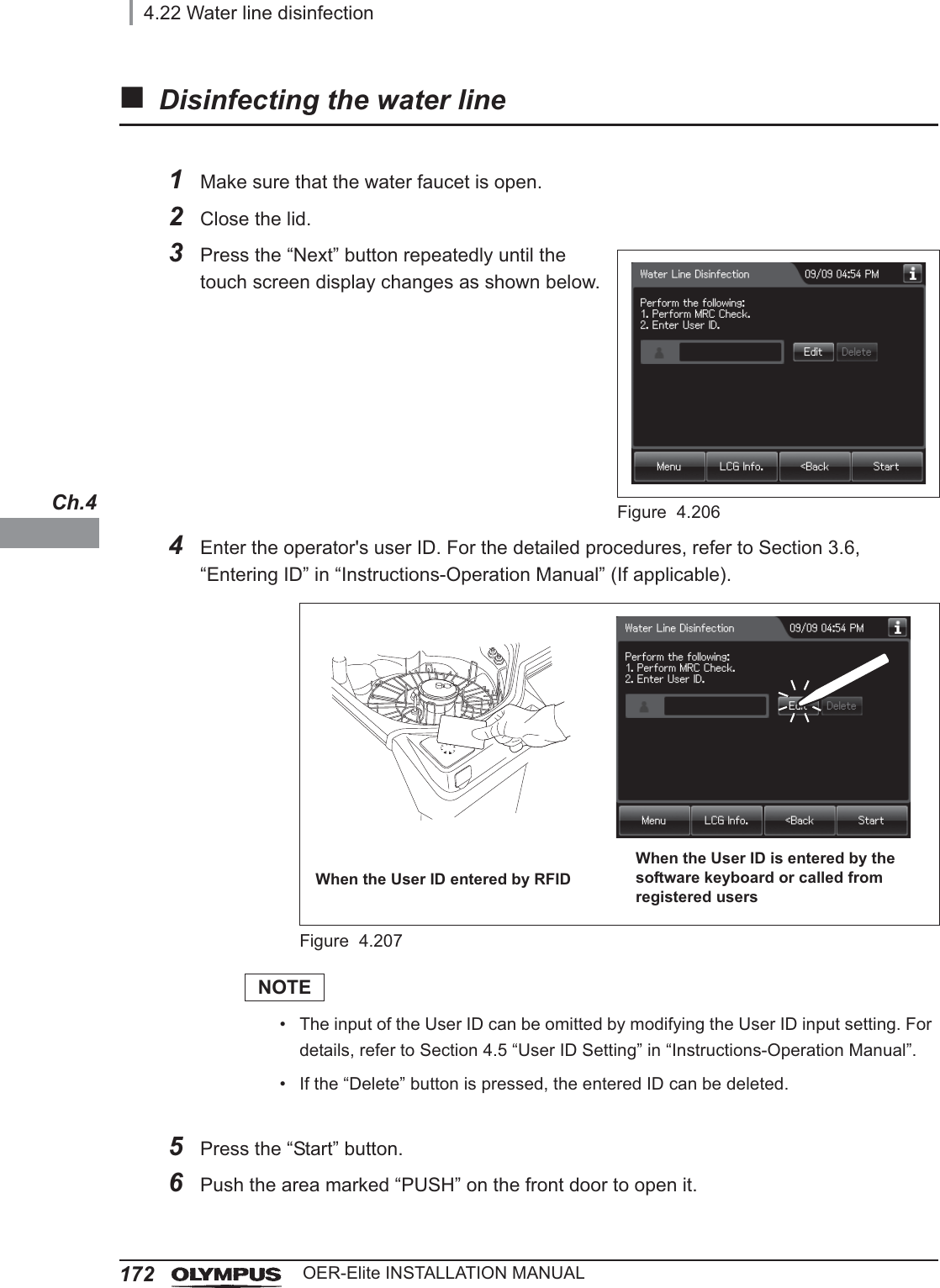
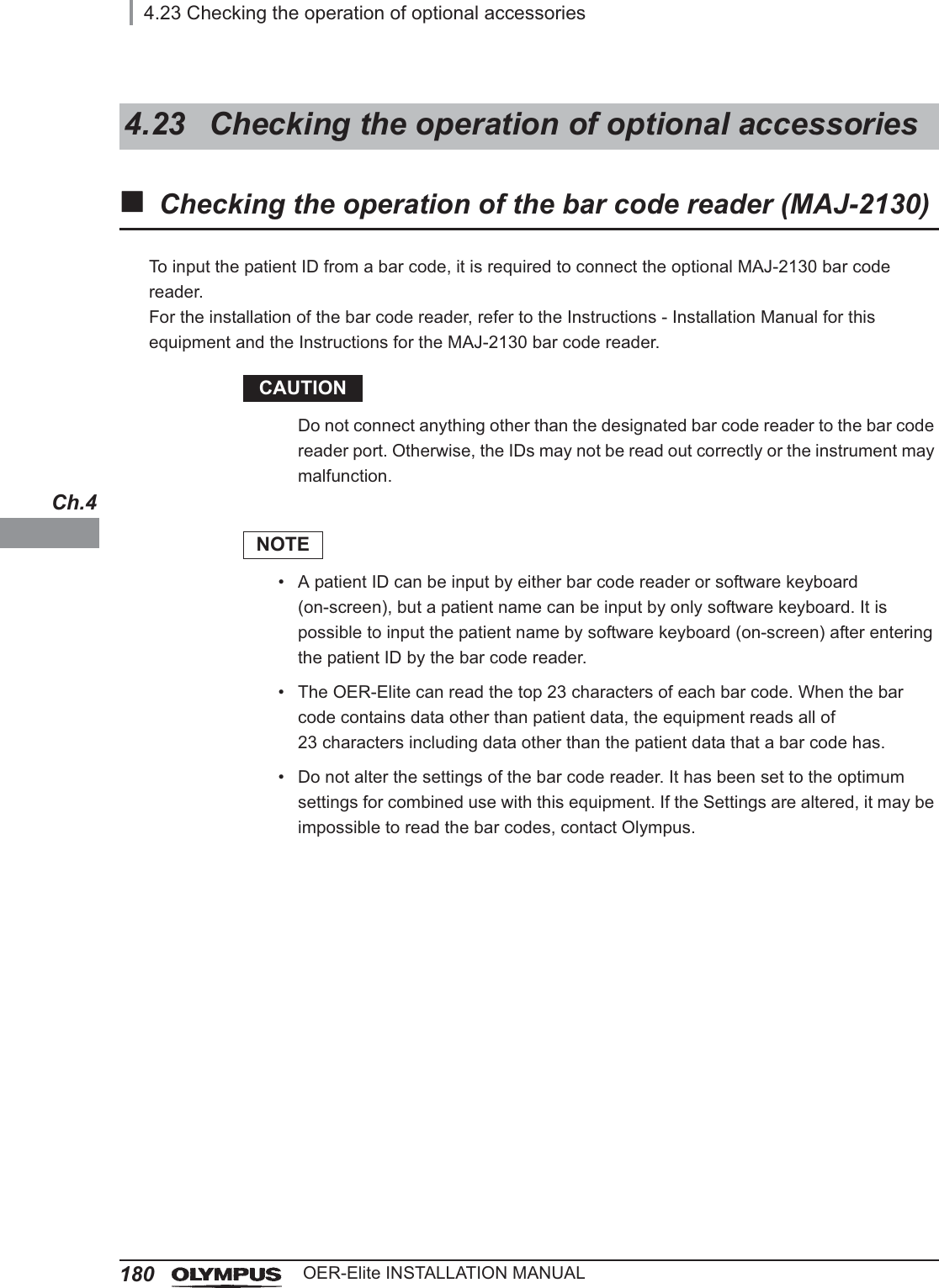
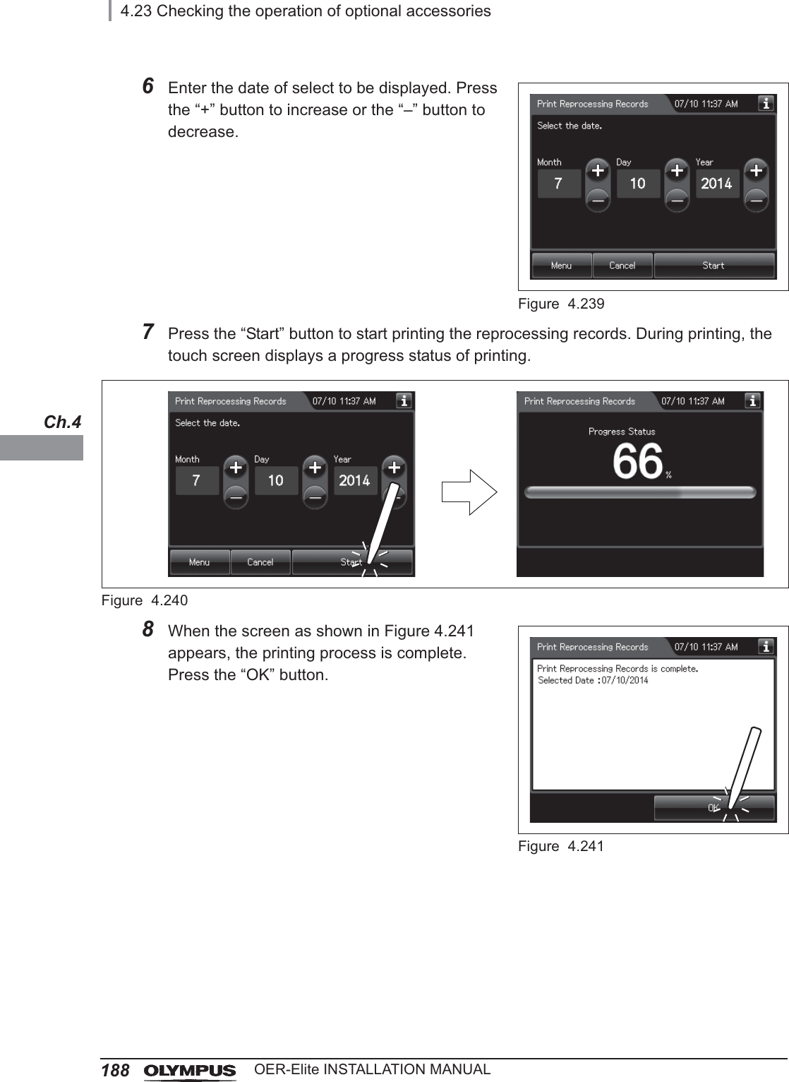
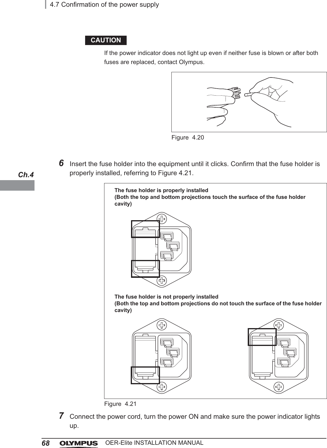
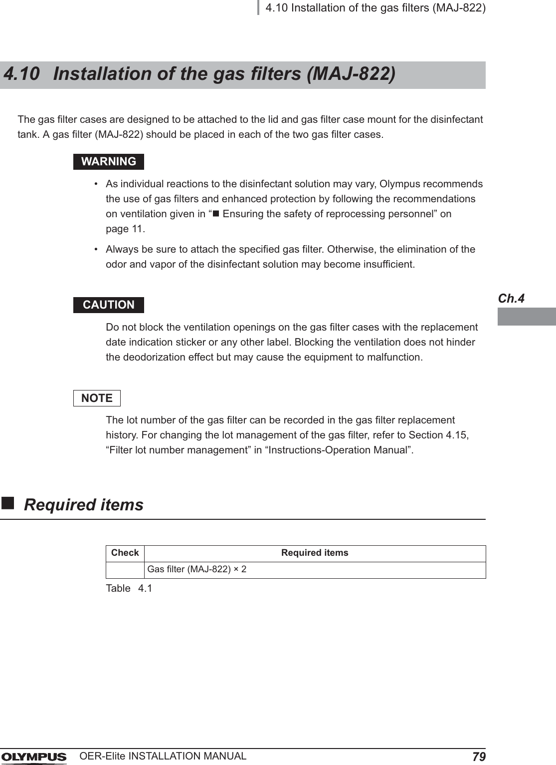
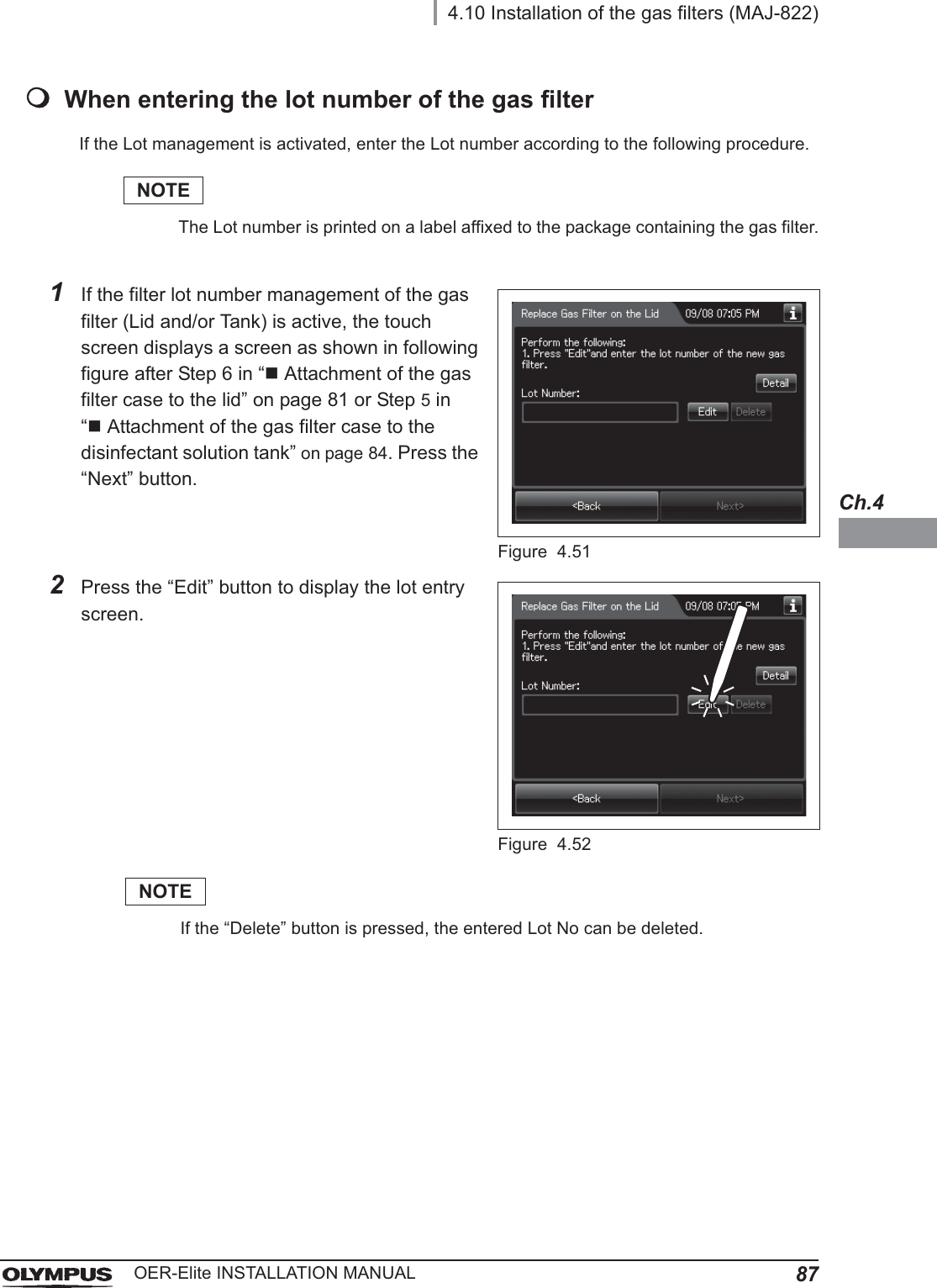
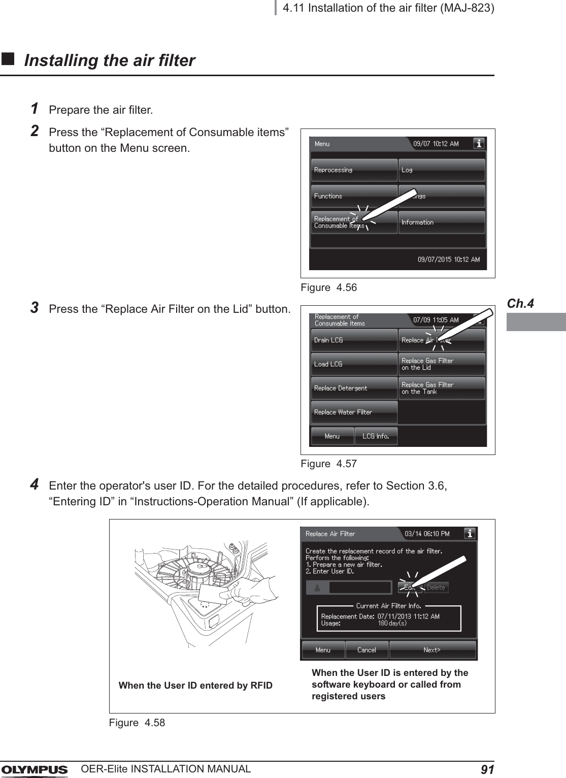
![4.13 Installation of the water tray99OER-Elite INSTALLATION MANUALCh.4The water tray is used to receive and hold water during maintenance such as water filter replacement.Push [PUSH] on the front door of the equipment to open the front door and place the water tray below the water filter.Figure 4.734.13 Installation of the water tray](https://usermanual.wiki/Olympus-Medical-Systems/RU2020.Installation-Manual-2/User-Guide-3575696-Page-39.png)
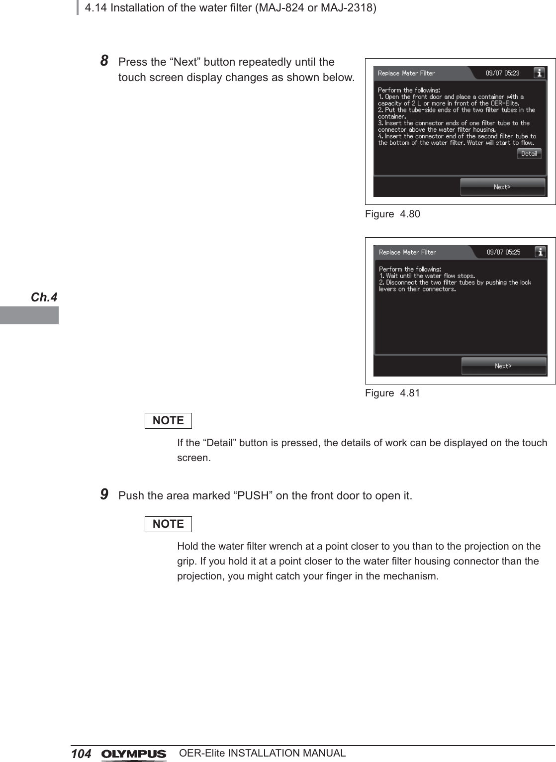
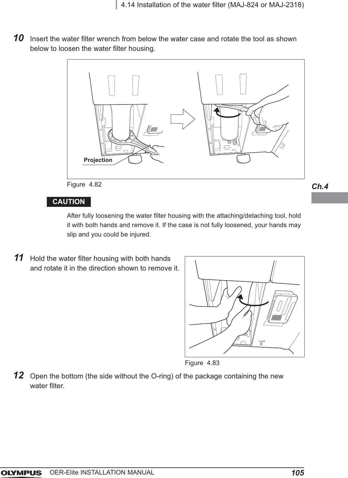
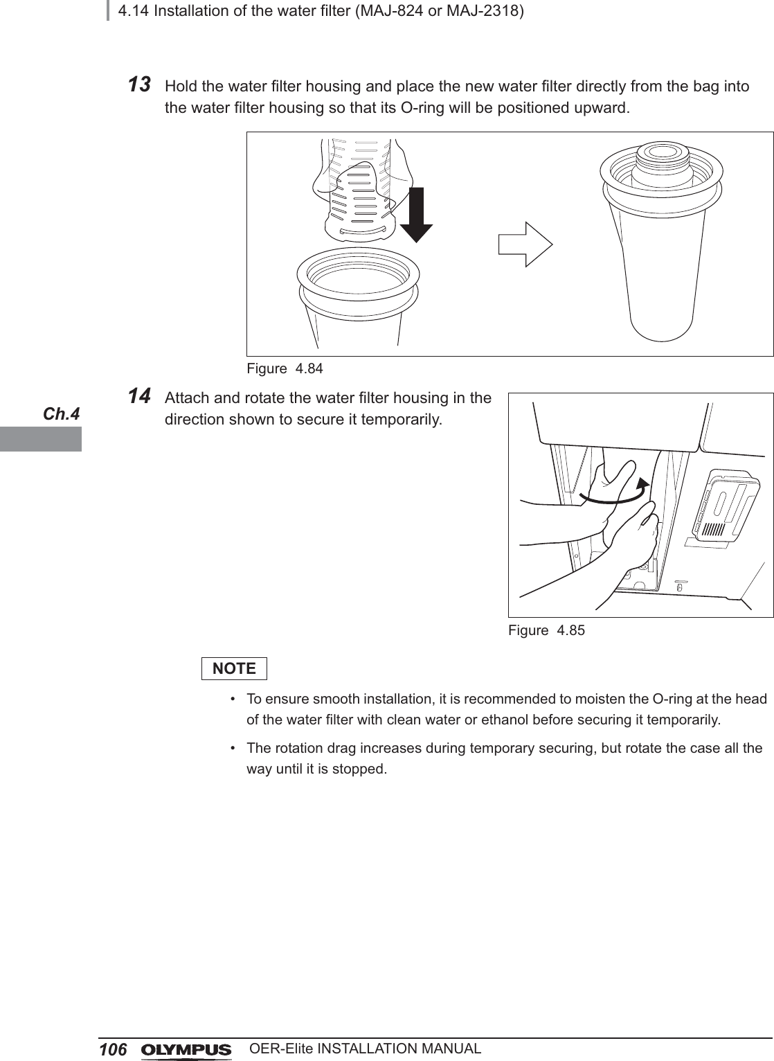
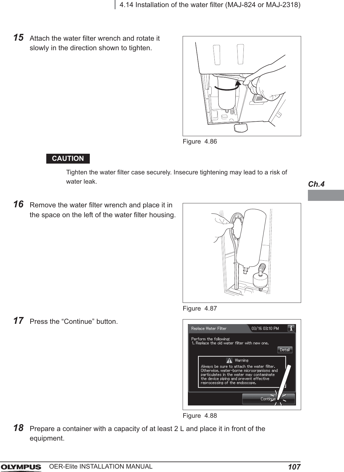
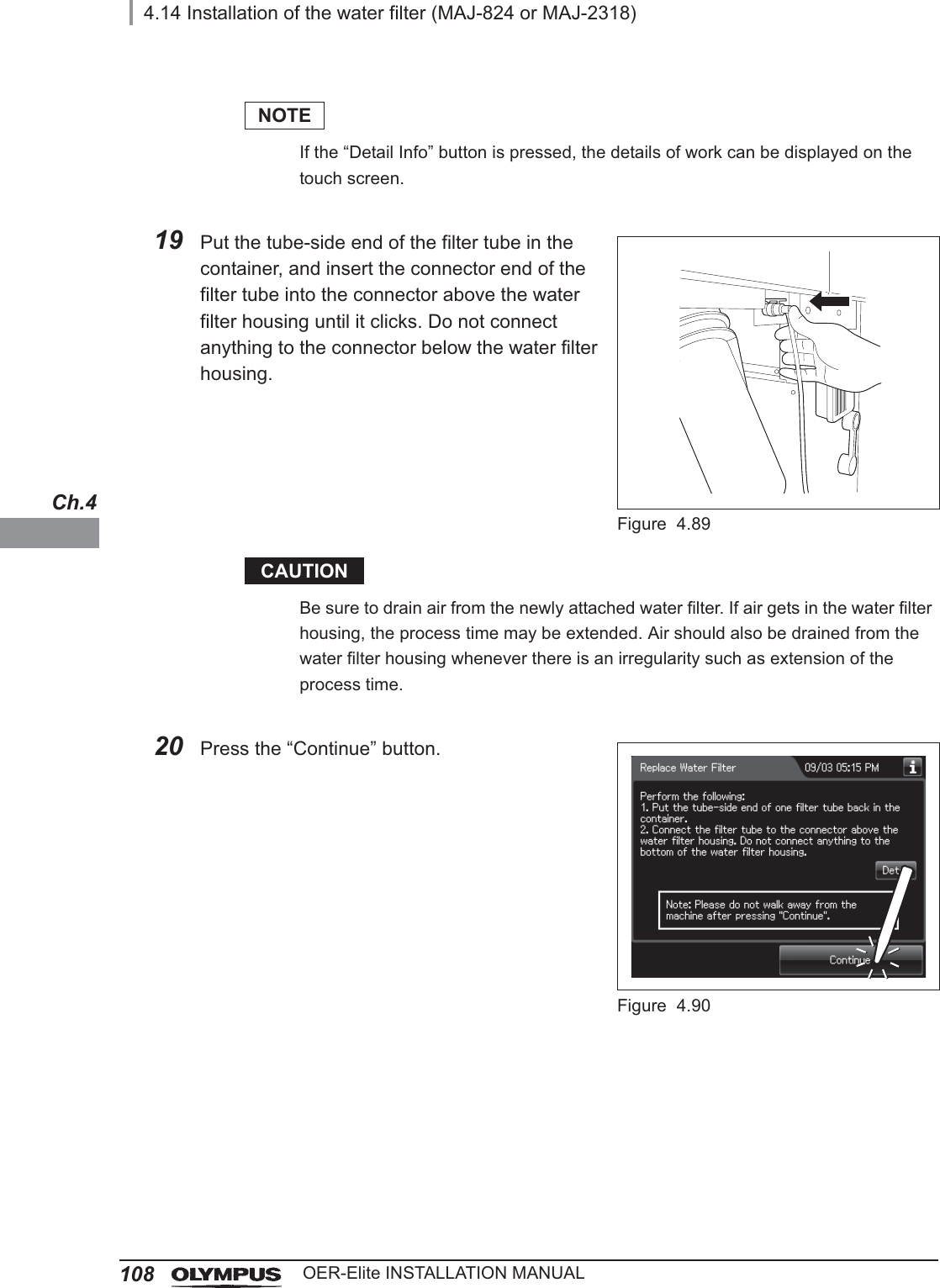
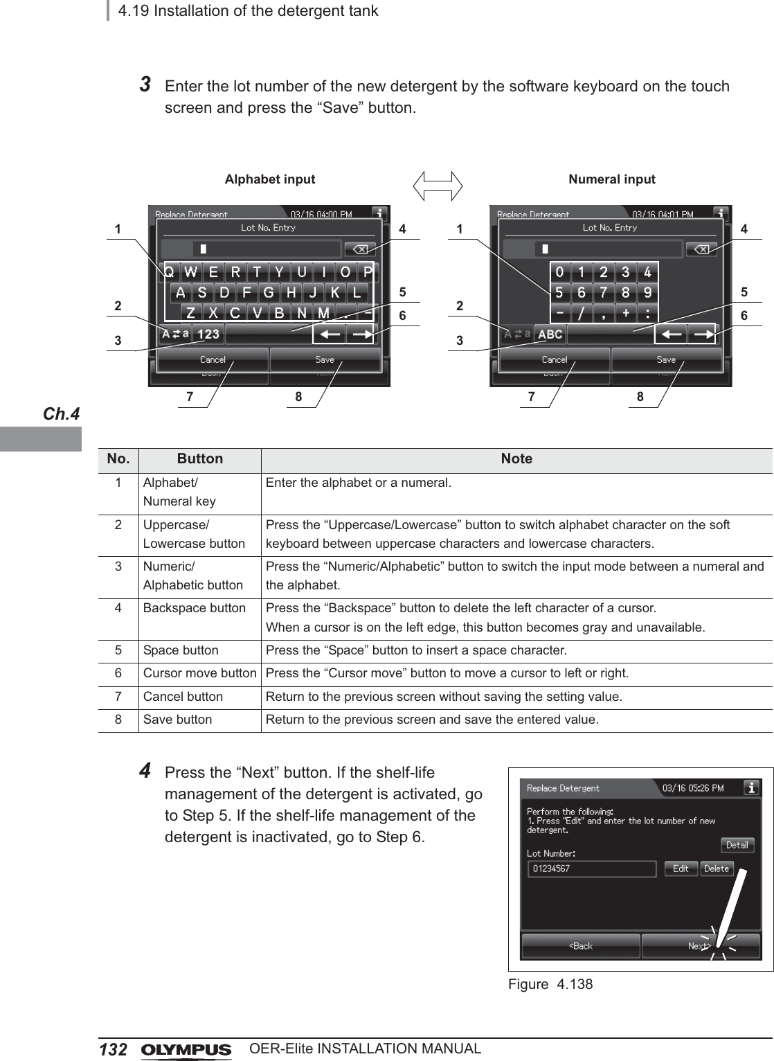
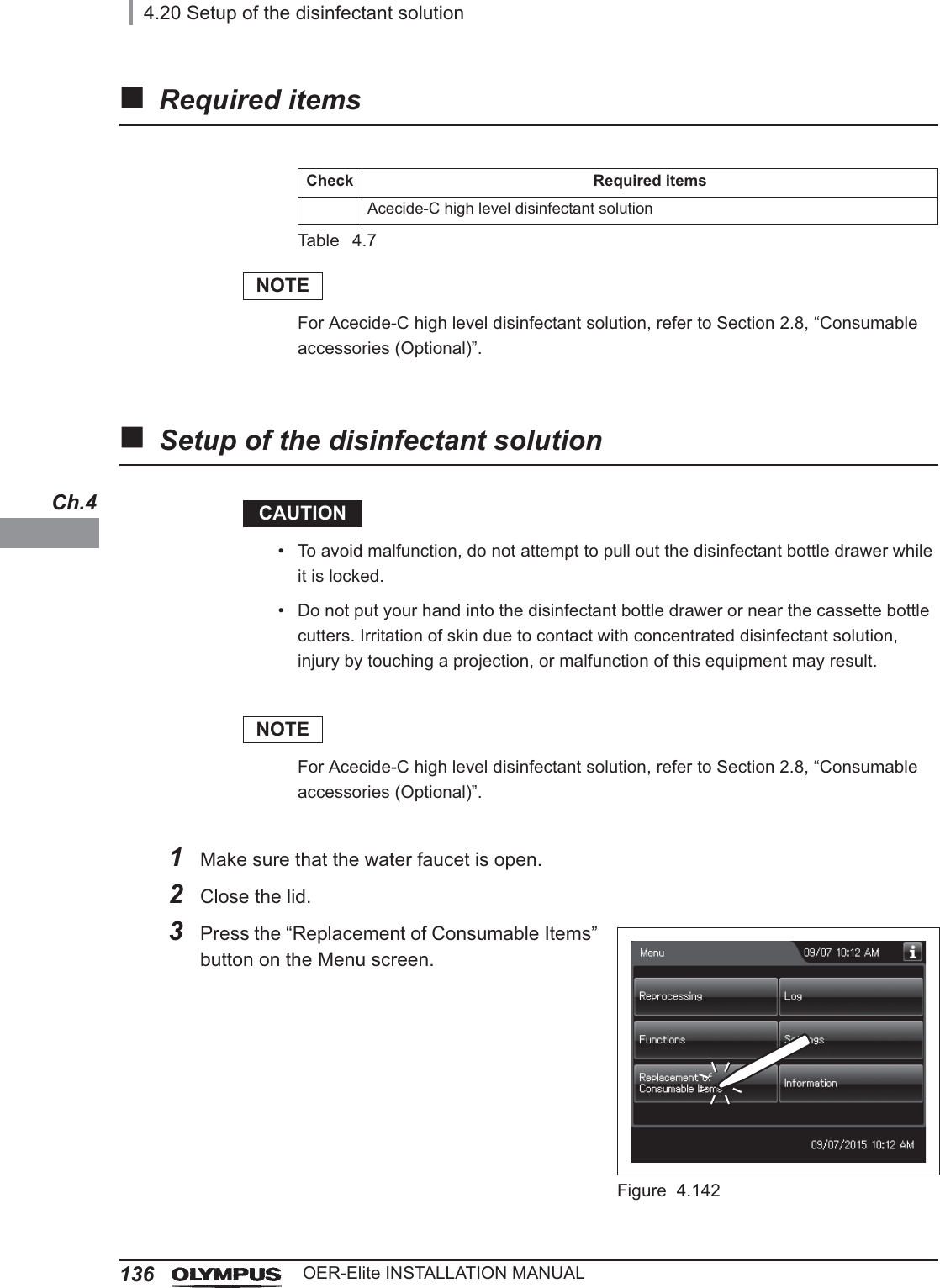
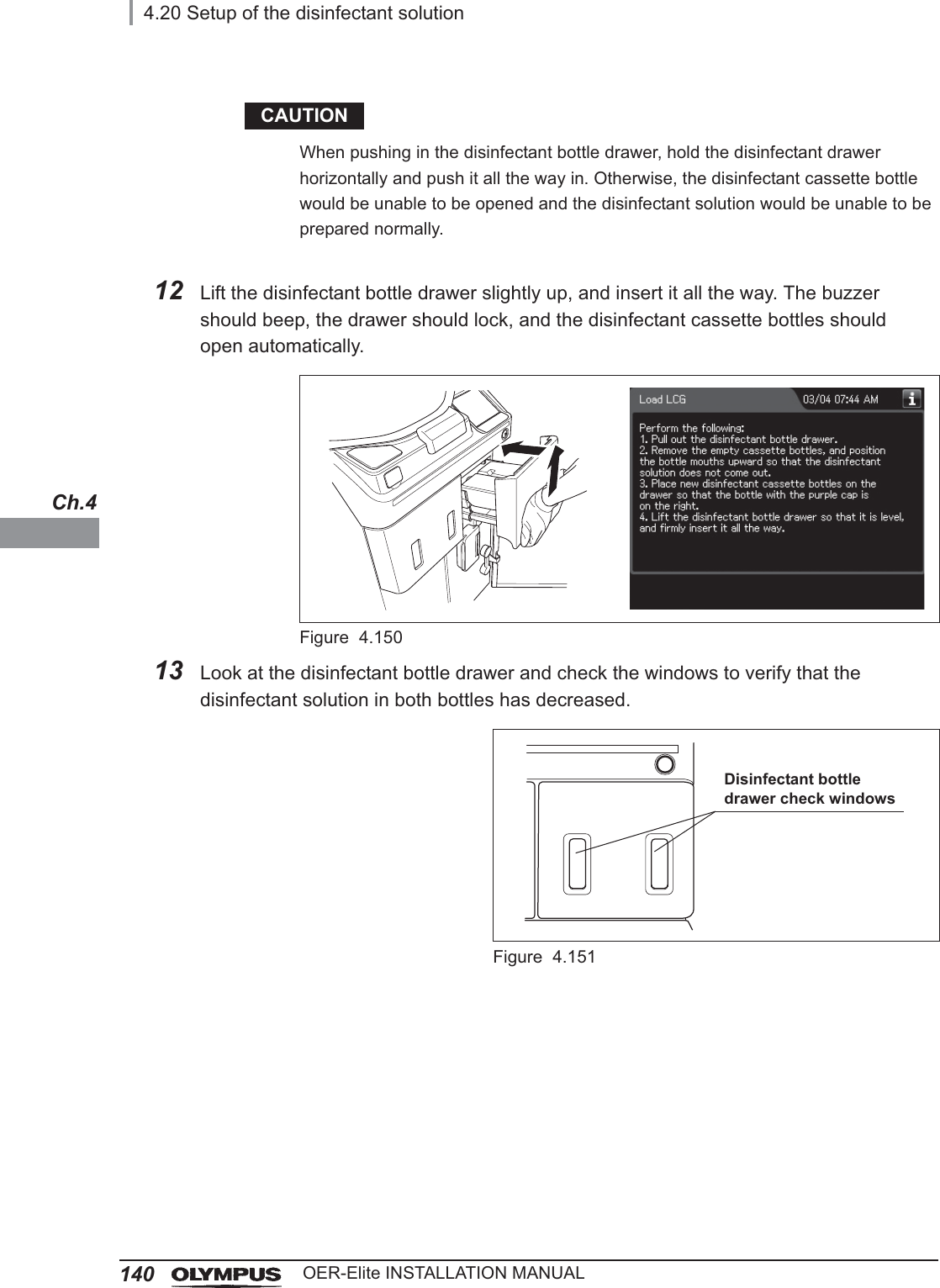
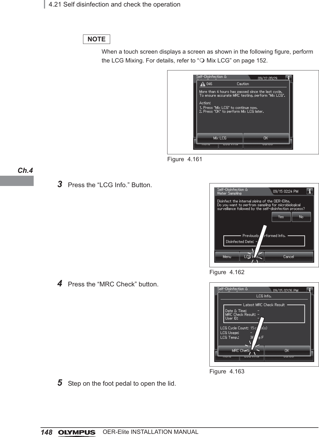
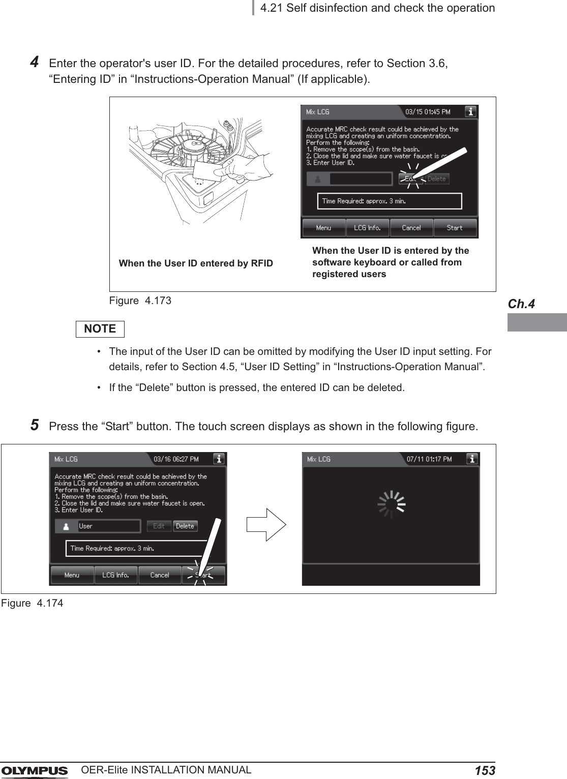
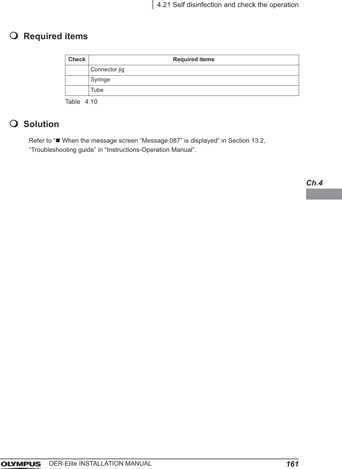
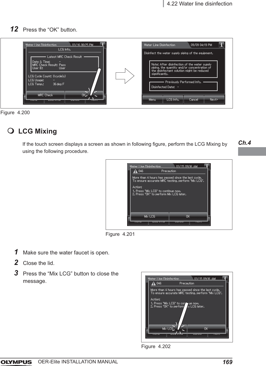
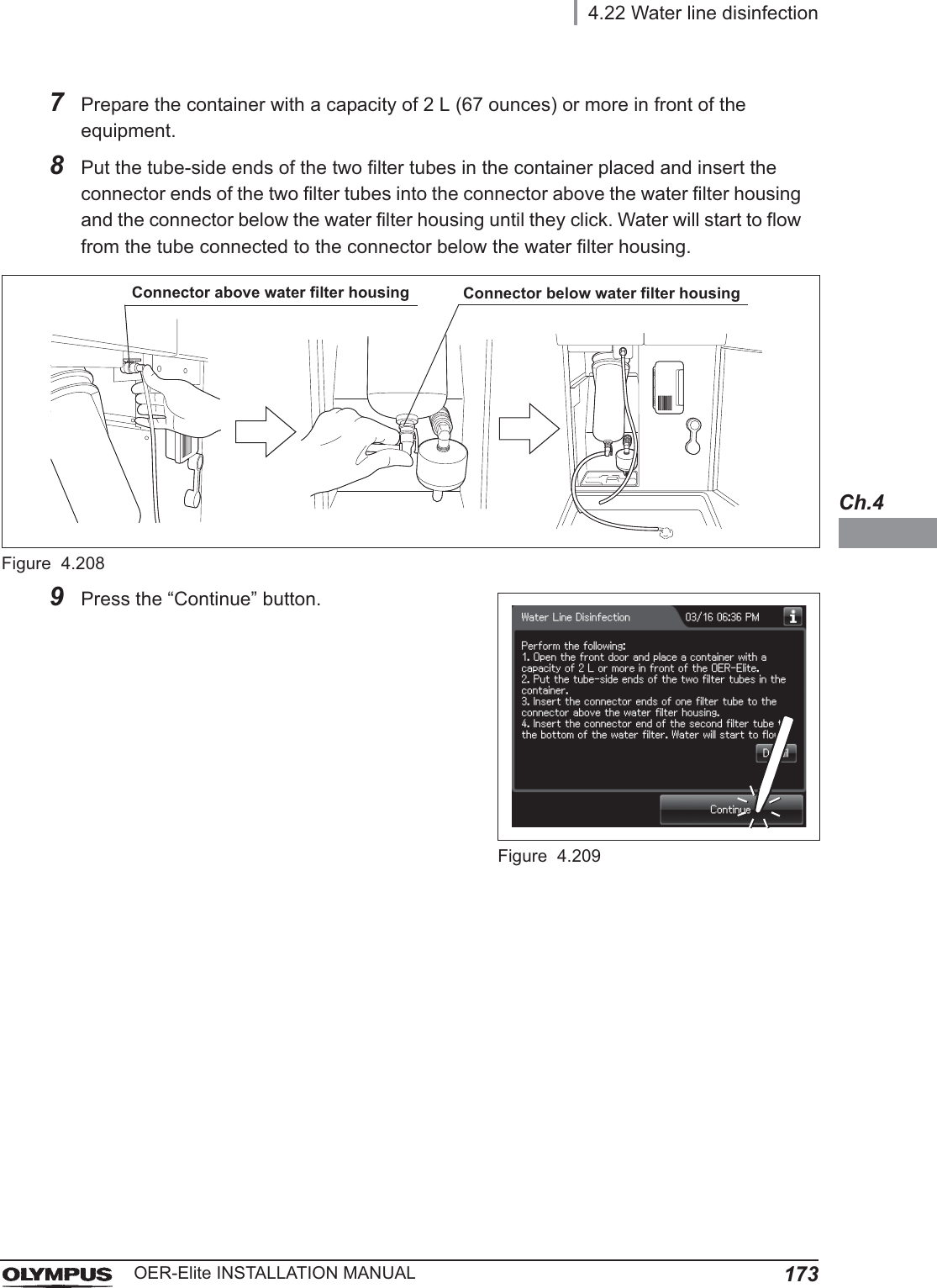
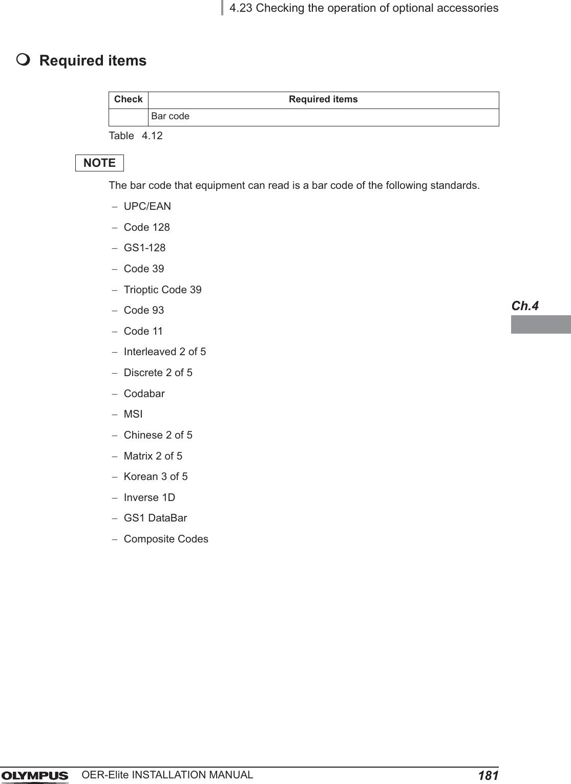
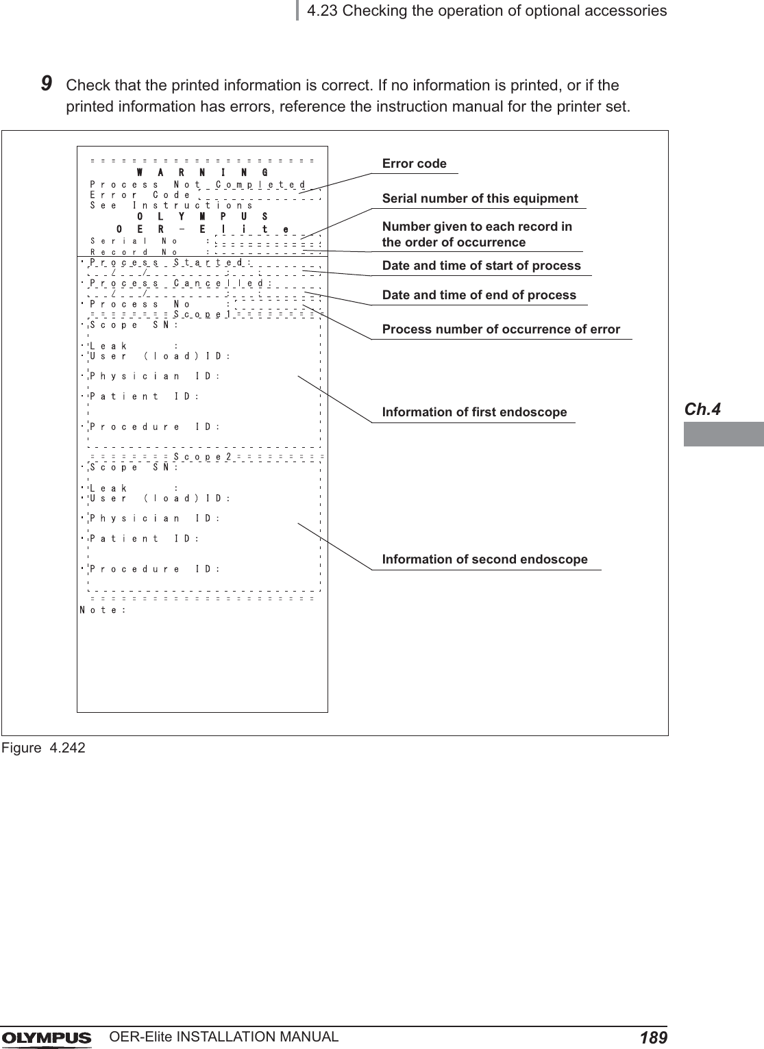
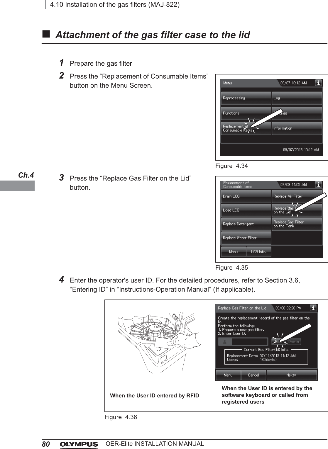
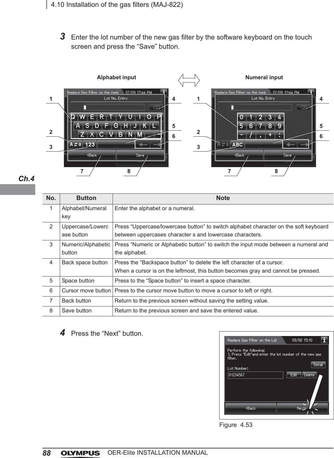
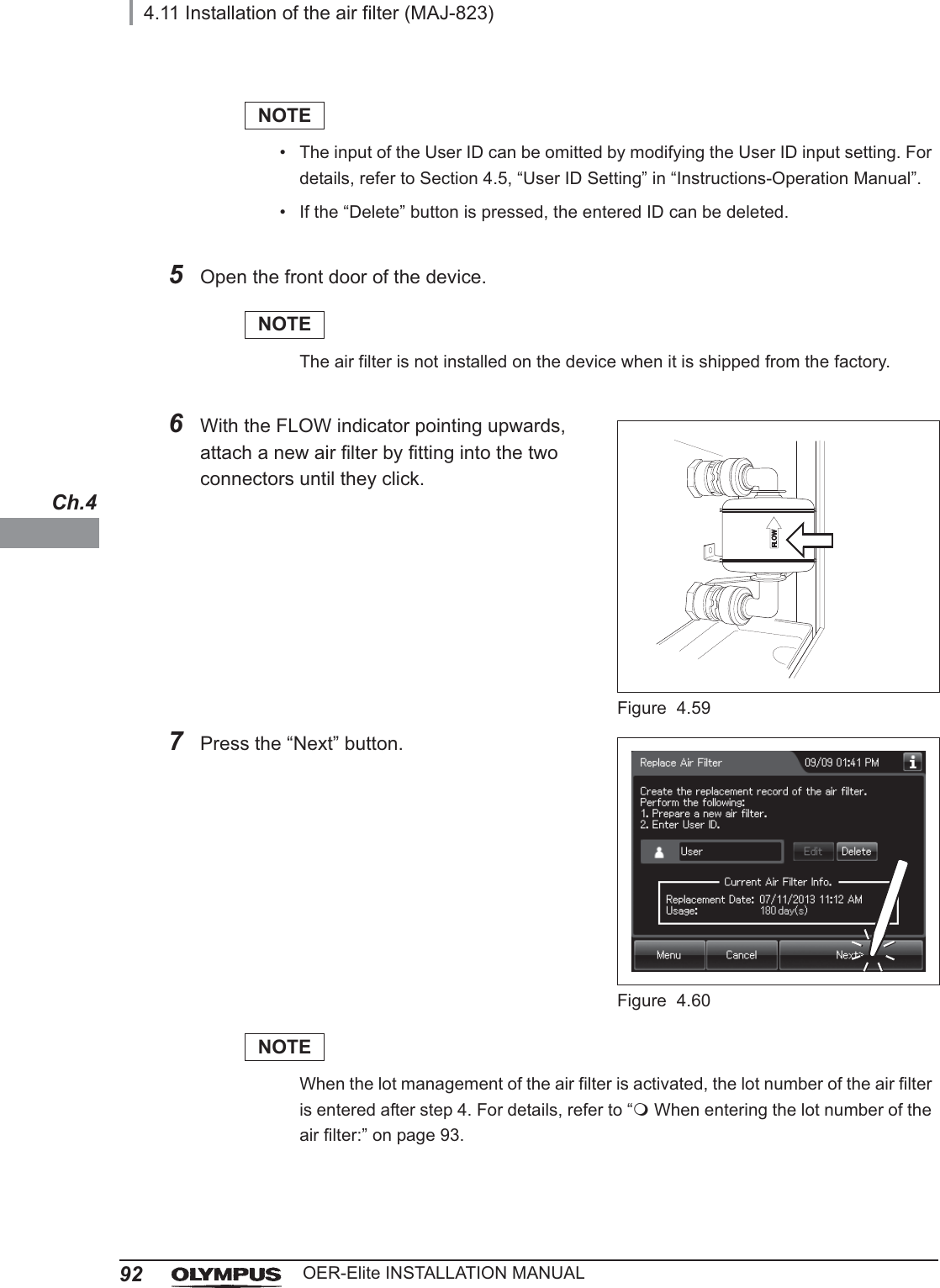
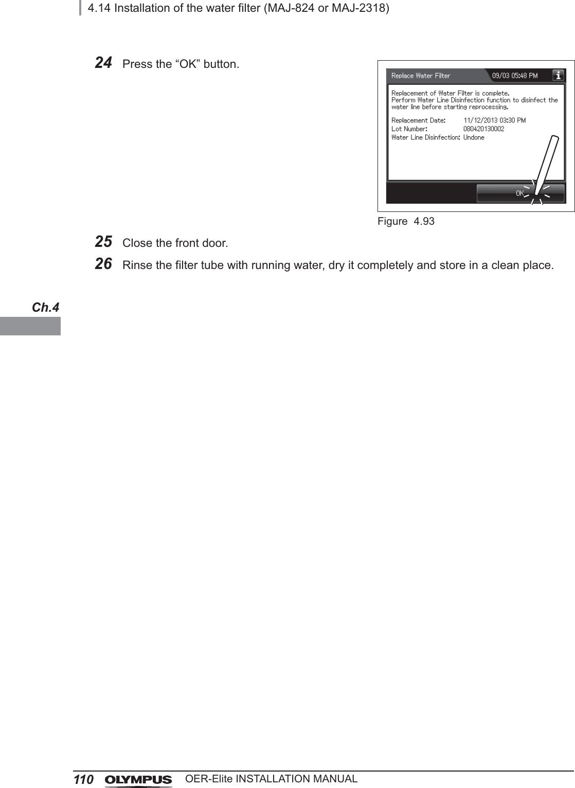
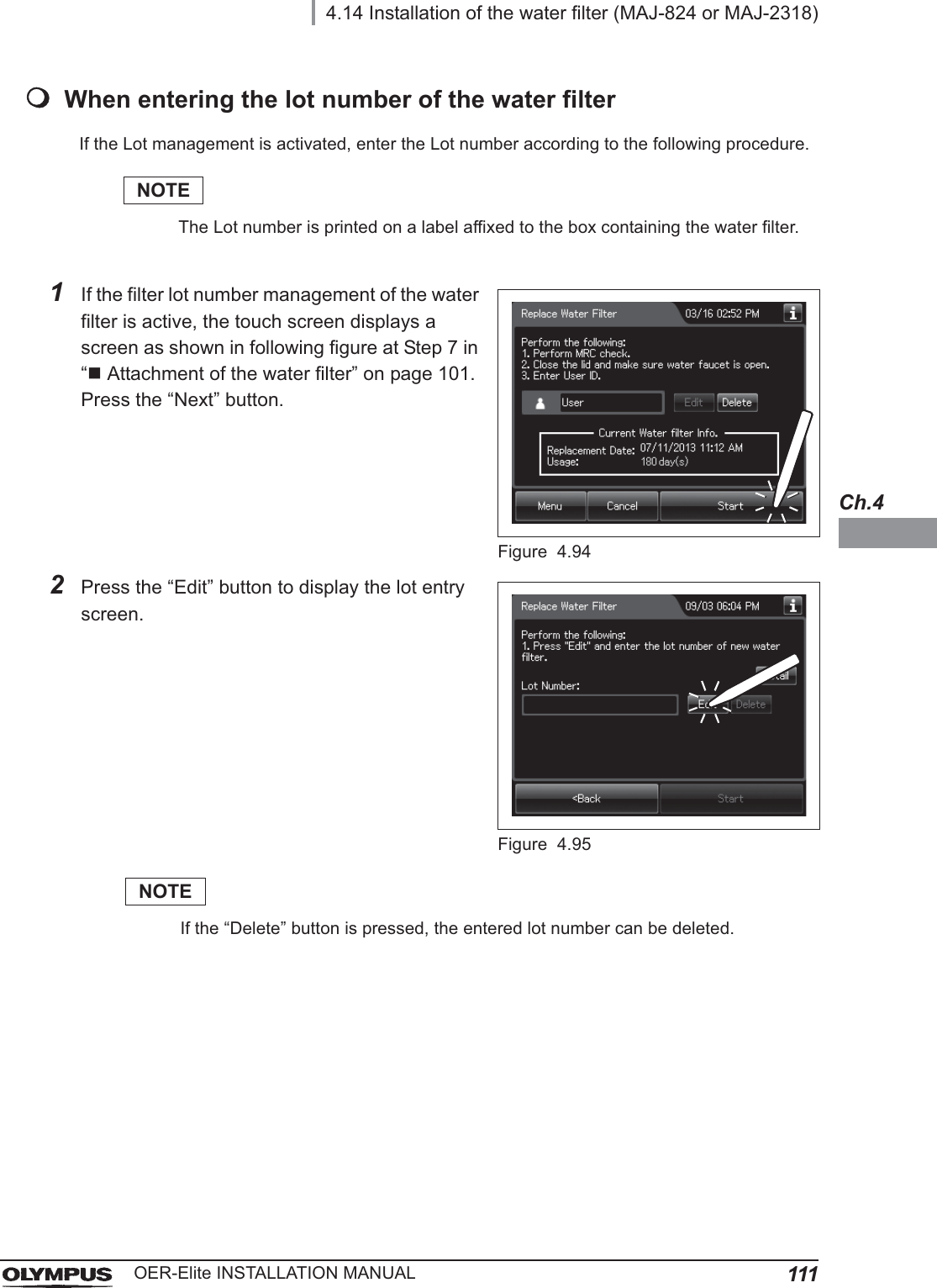
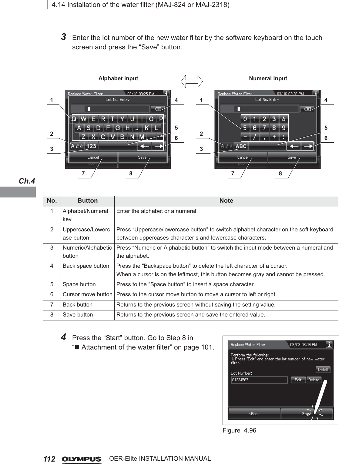
![4.14 Installation of the water filter (MAJ-824 or MAJ-2318)109OER-Elite INSTALLATION MANUALCh.421 When water starts to flow continuously from the filter tube, disconnect the tube by pushing its lock lever. Water flow should stop when the filter tube is disconnected.Figure 4.9122 Check that no water Leaks from the water filter housing. If a Leak is detected, immediately press the “STOP” button to stop water supply and reinstall the water filter (perform as described in Section 8.4, “Replacing the water filter (MAJ-824 or MAJ-2318)” in the “Instructions-Operation Manual”).NOTEWhen the “Stop” button is pressed to stop the process, error code [E000] is displayed and the auto processing is executed.23 Press the “Continue” button.Figure 4.92](https://usermanual.wiki/Olympus-Medical-Systems/RU2020.Installation-Manual-2/User-Guide-3575696-Page-49.png)
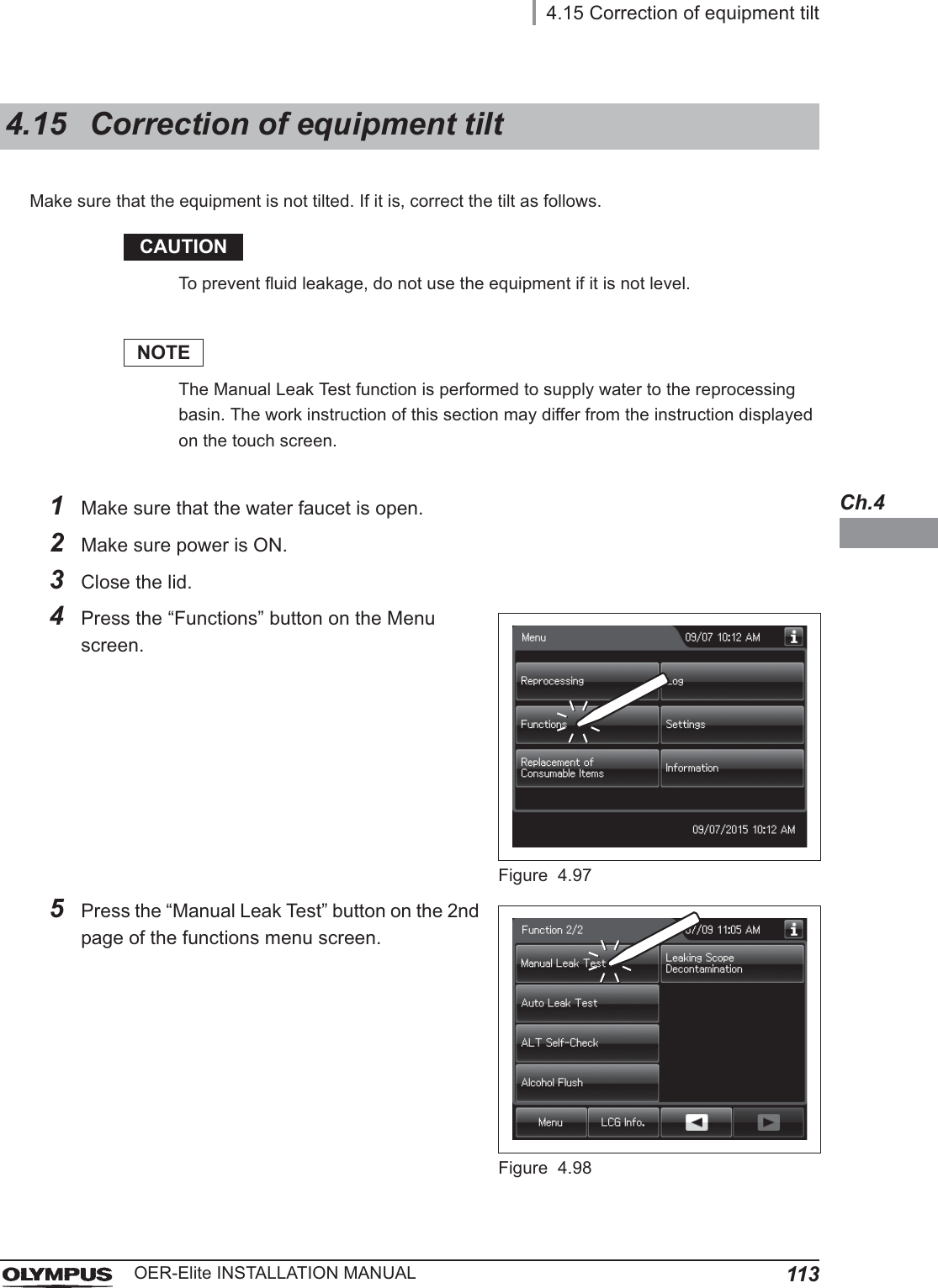
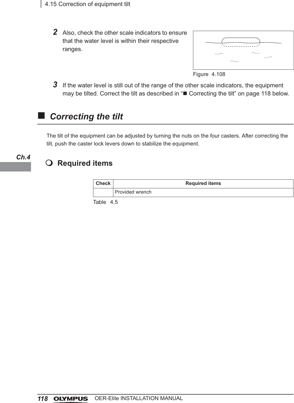
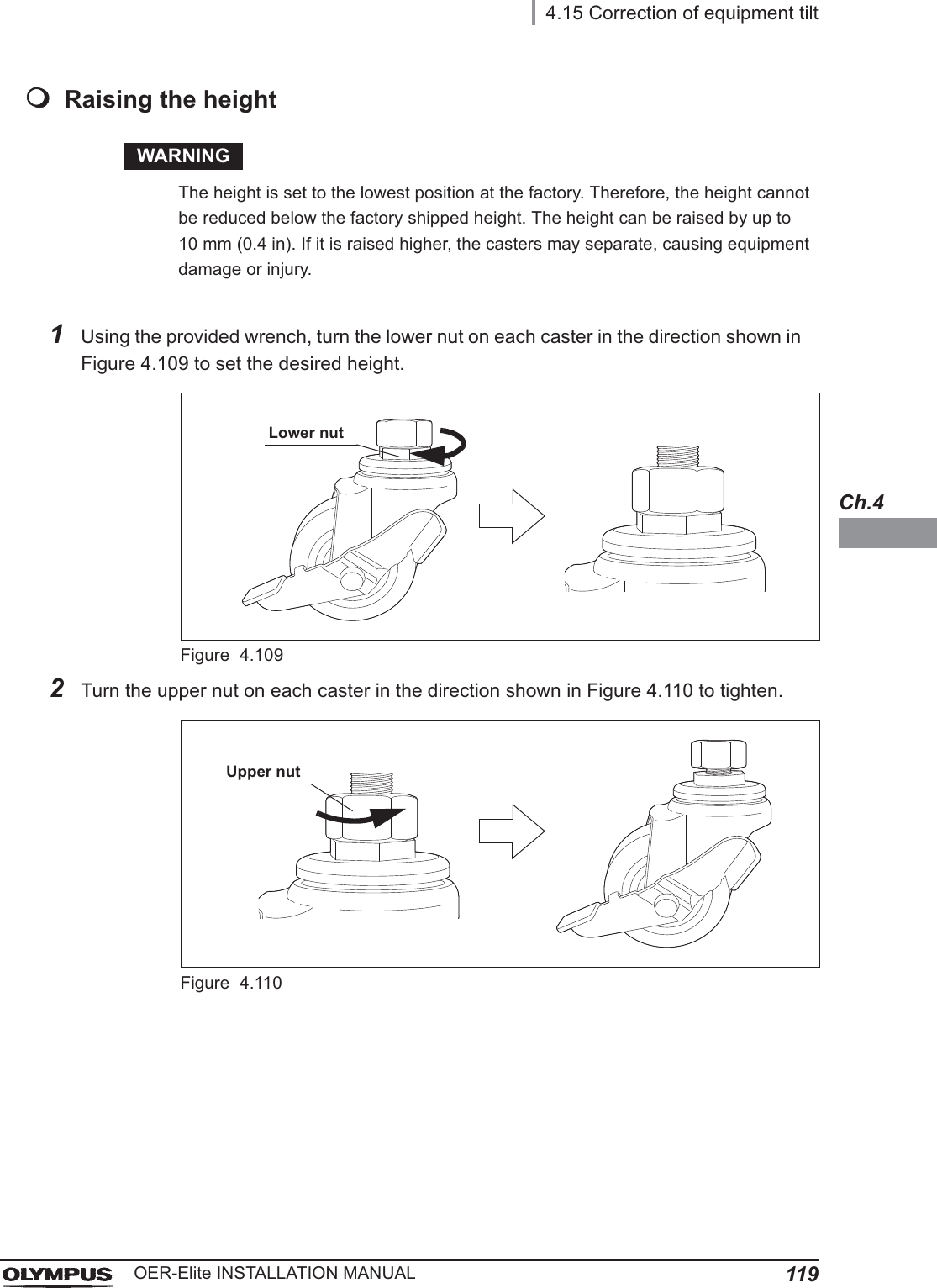
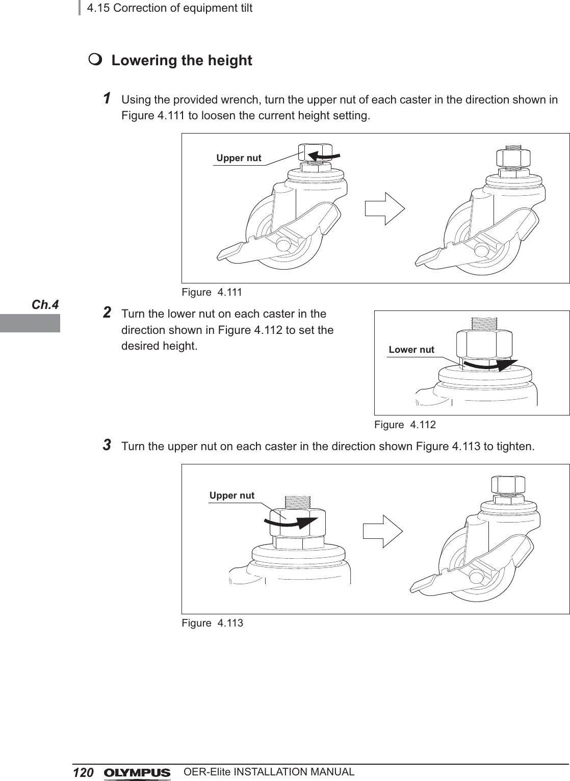
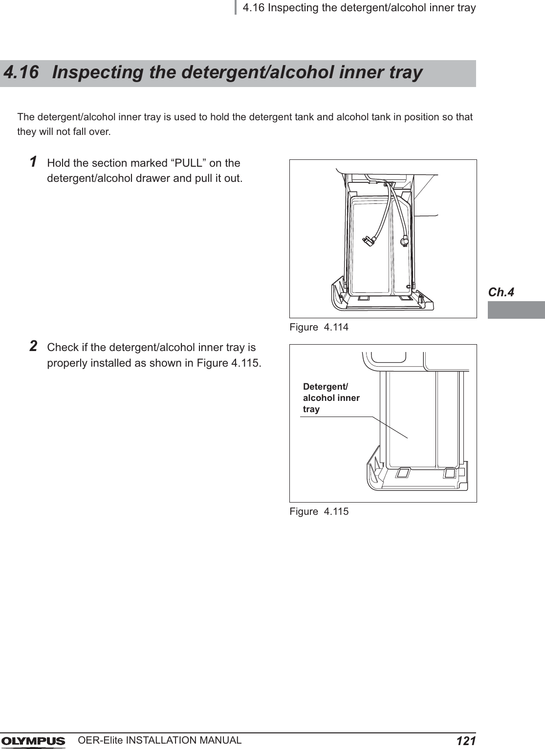
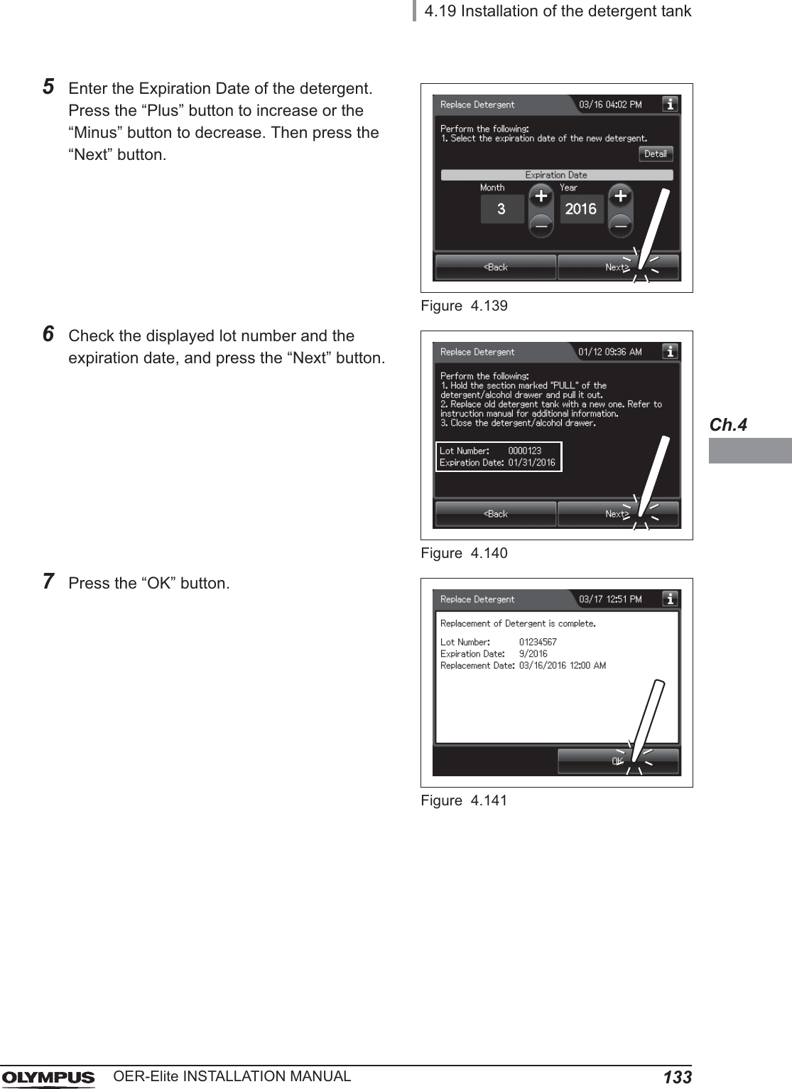
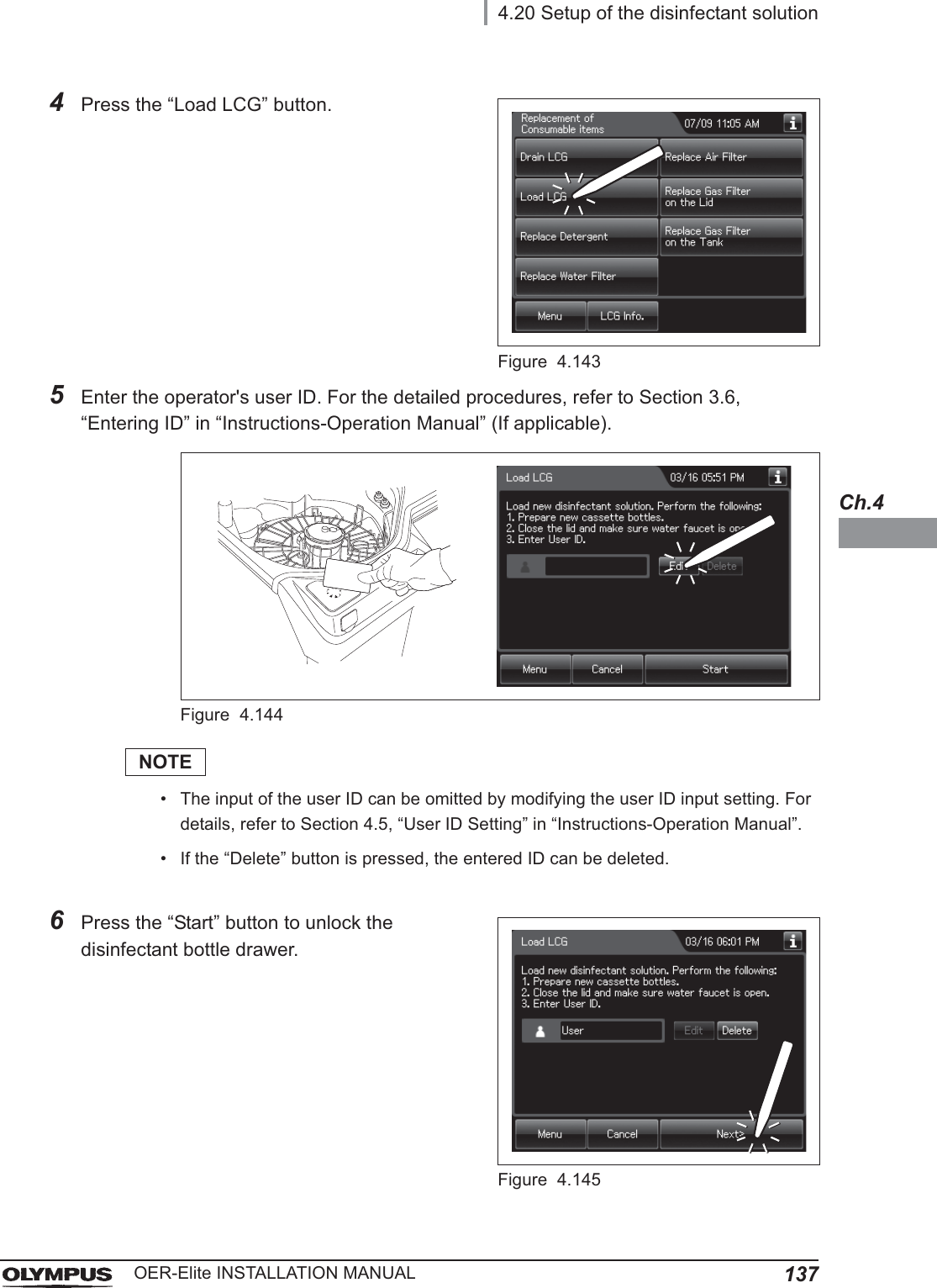
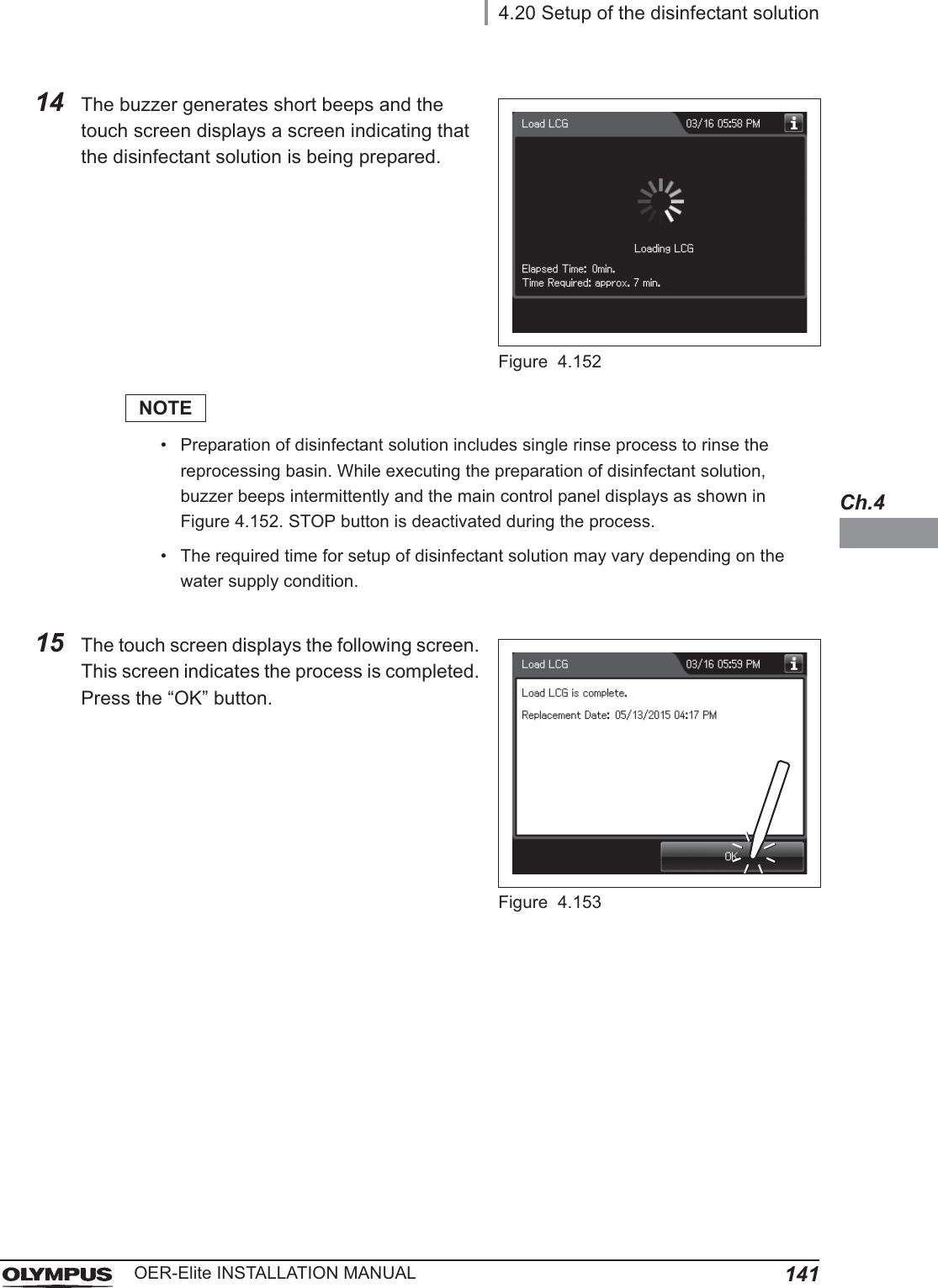
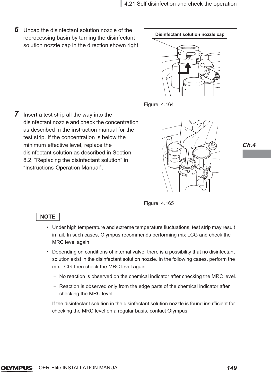
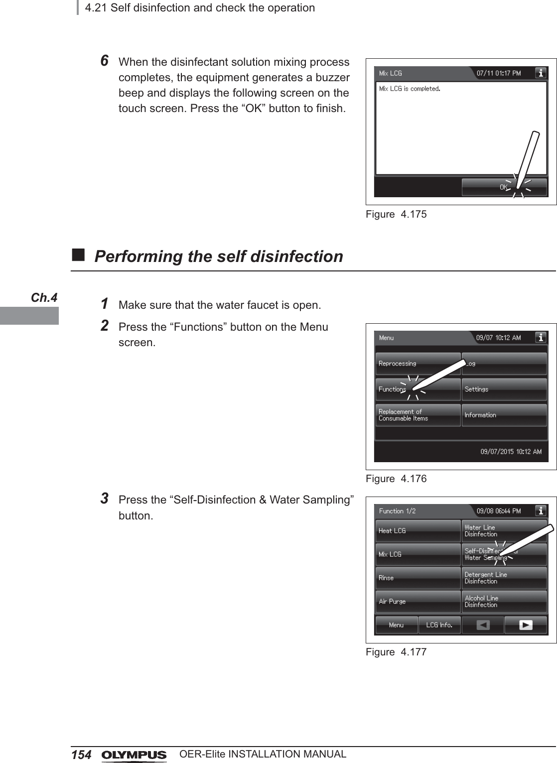
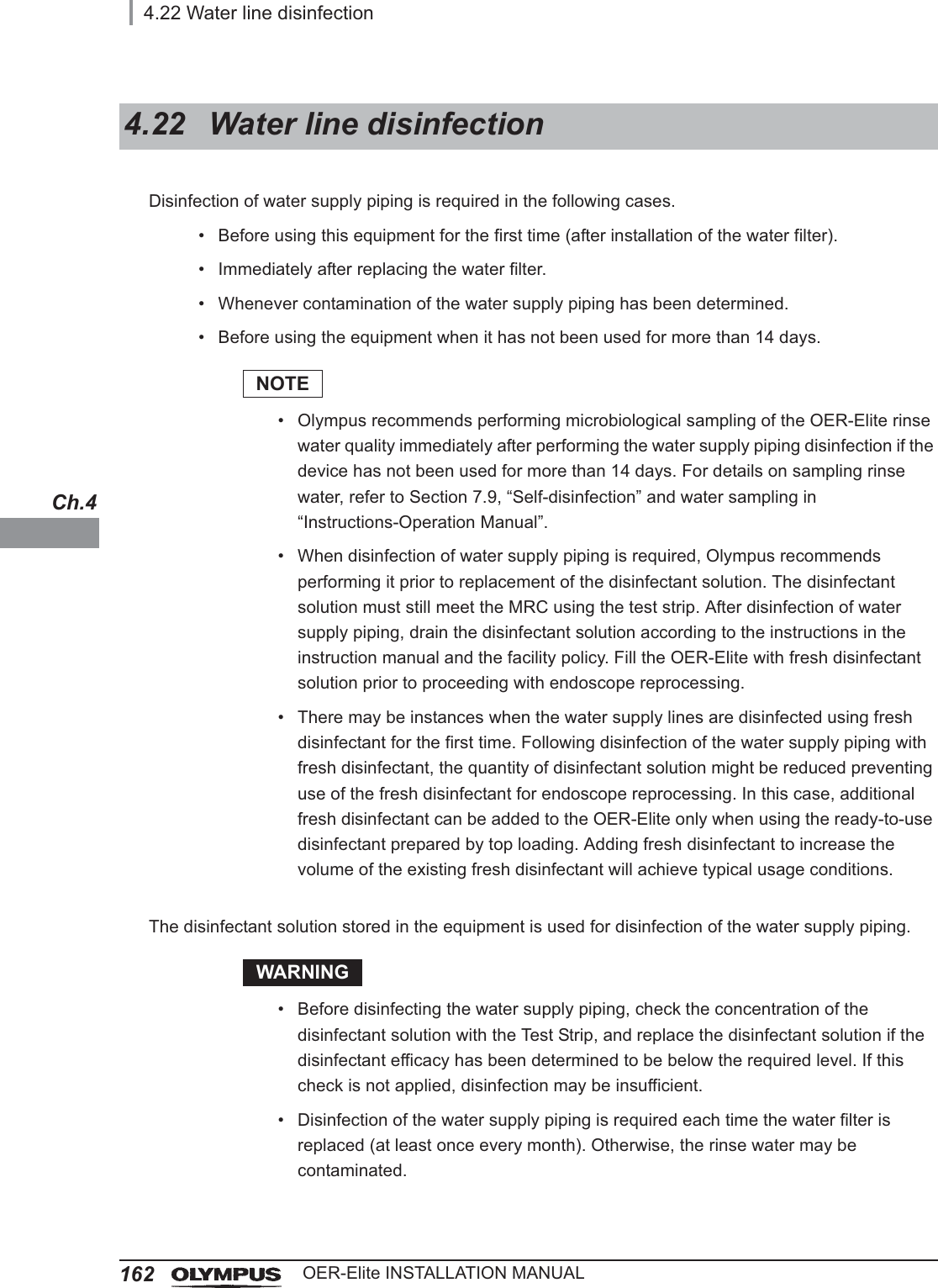
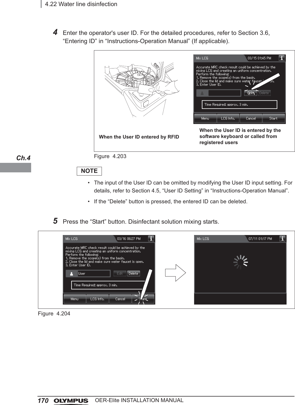
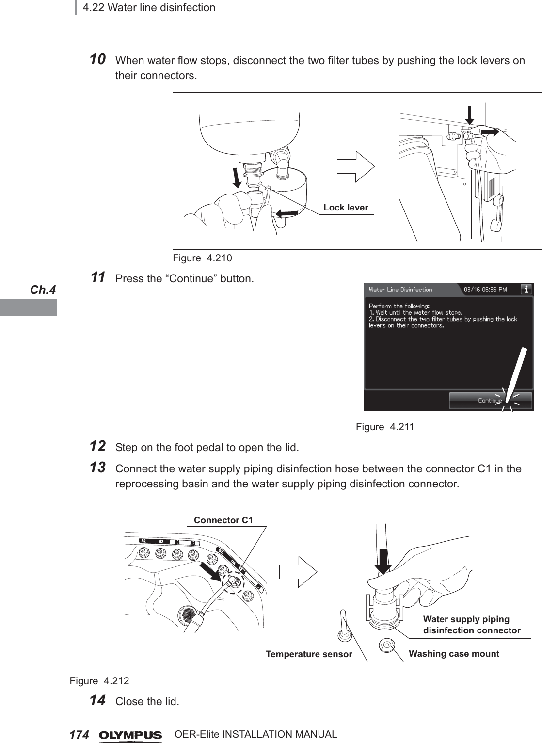
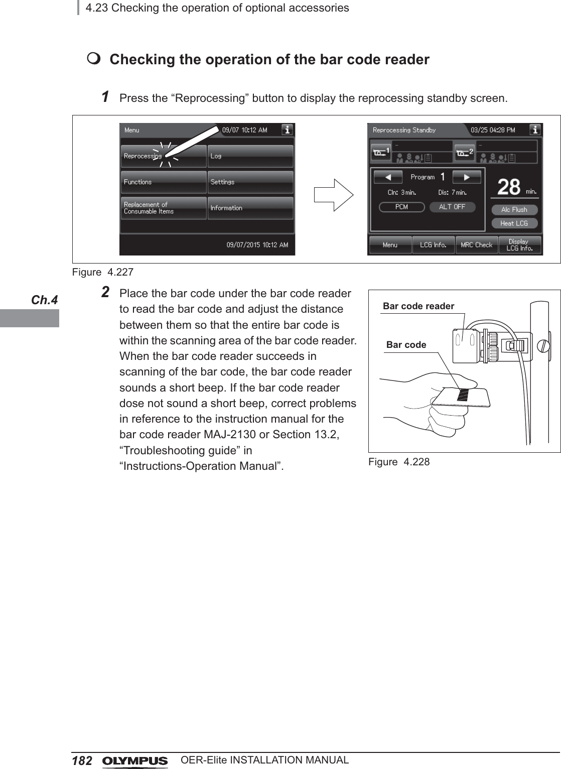
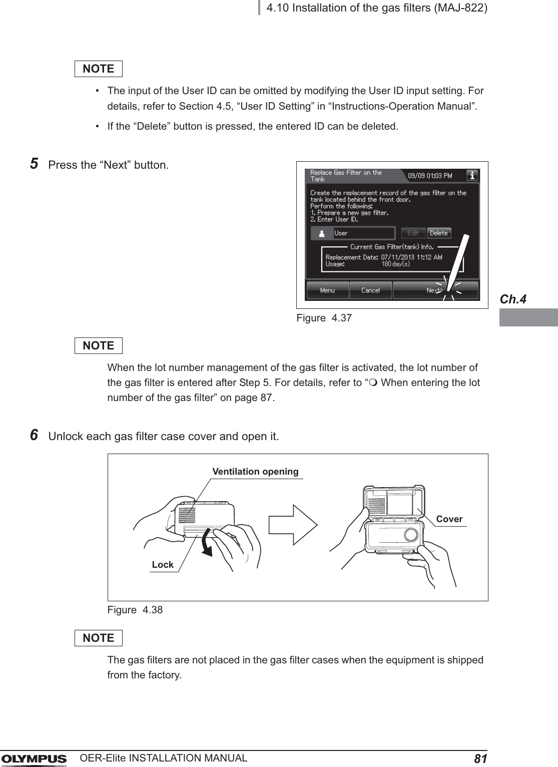
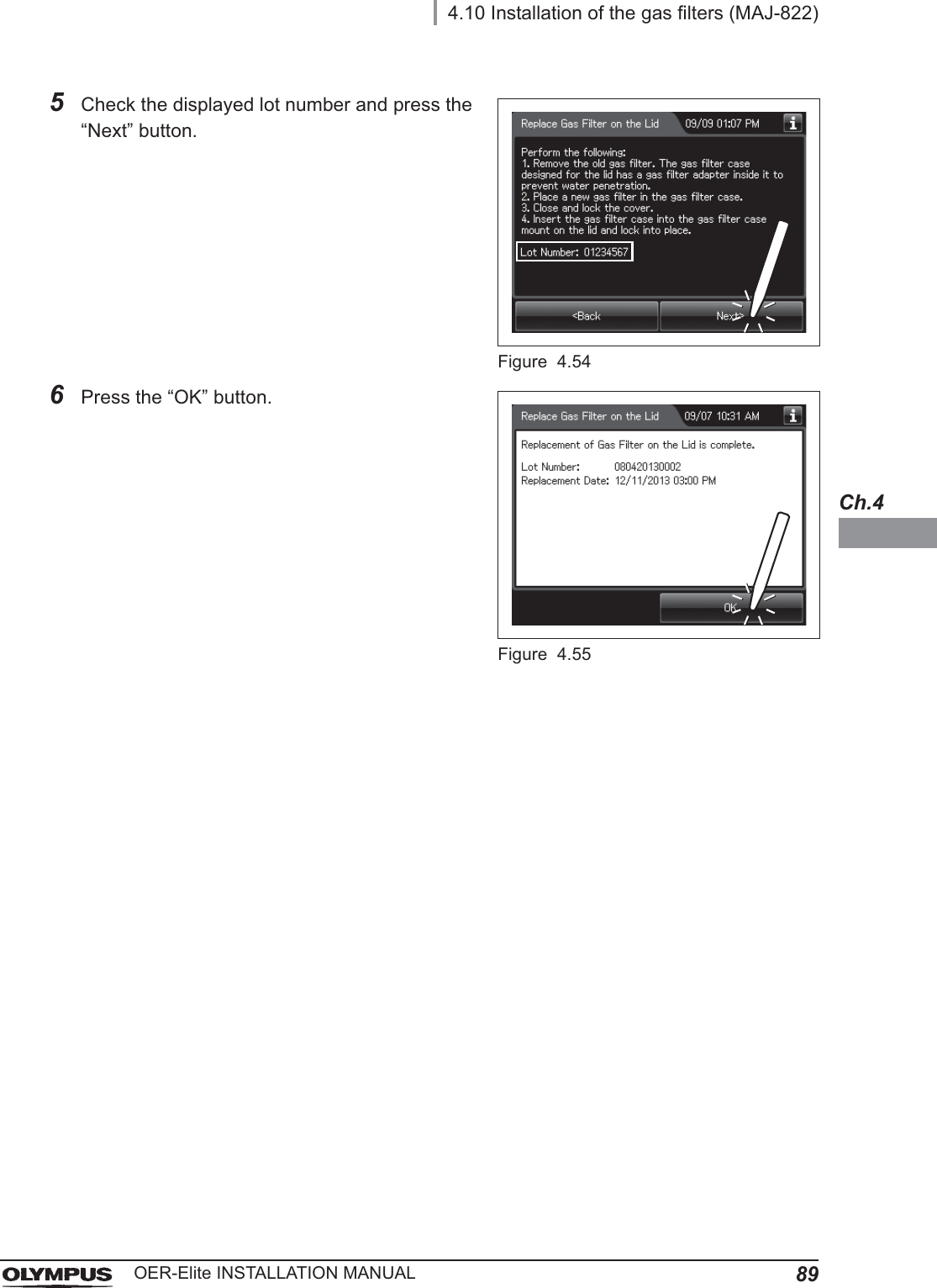
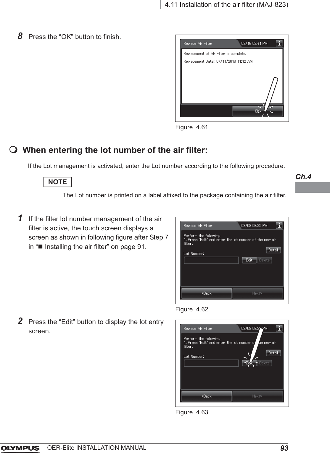
![4.15 Correction of equipment tilt117OER-Elite INSTALLATION MANUALCh.4Adjustment if water level is not located within even one of the three rangesRequired itemsTable 4 . 4NOTEEven if the process is not completed by closing the lid, the water is drained automatically 10 minutes after the water supply stopped. The touch screen will then display error code [E092].16 When draining has completed, the equipment generates three buzzer beeps and the touchscreen shows the following screen. Press the “OK” button to finish.Figure 4.106Check Required itemsContainer such as a cup1Check the water level. Using a cup, add or remove water until the water level reaches the scale indicator that had the largest deviation from the water level.Figure 4.107Water levelScale indicatorWater levelRange](https://usermanual.wiki/Olympus-Medical-Systems/RU2020.Installation-Manual-2/User-Guide-3575696-Page-57.png)