OJMAR OJM001 Electromechanical lock User Manual v2
OJMAR S.A. Electromechanical lock v2
UserManual.wiki
>
OJMAR
>
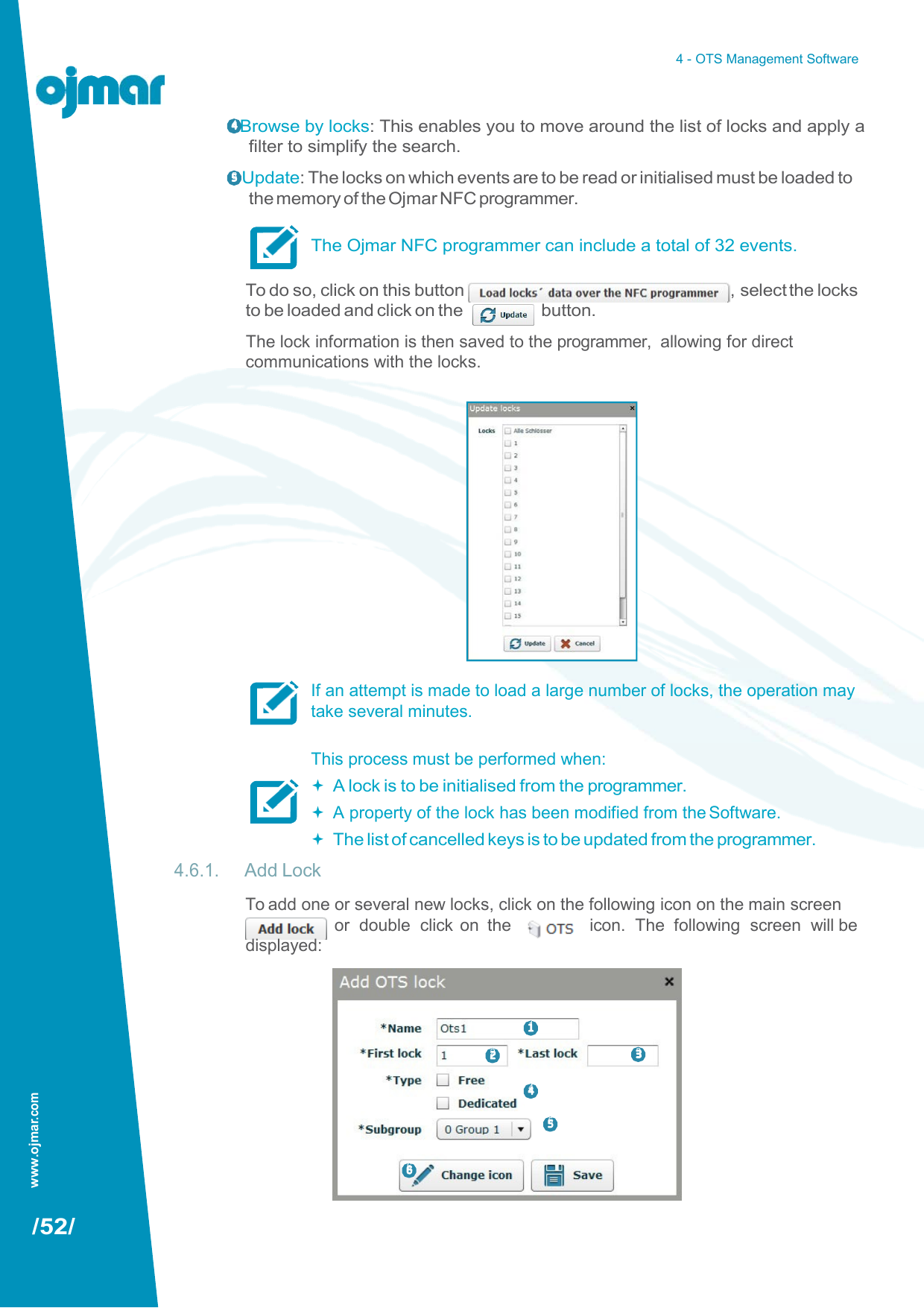
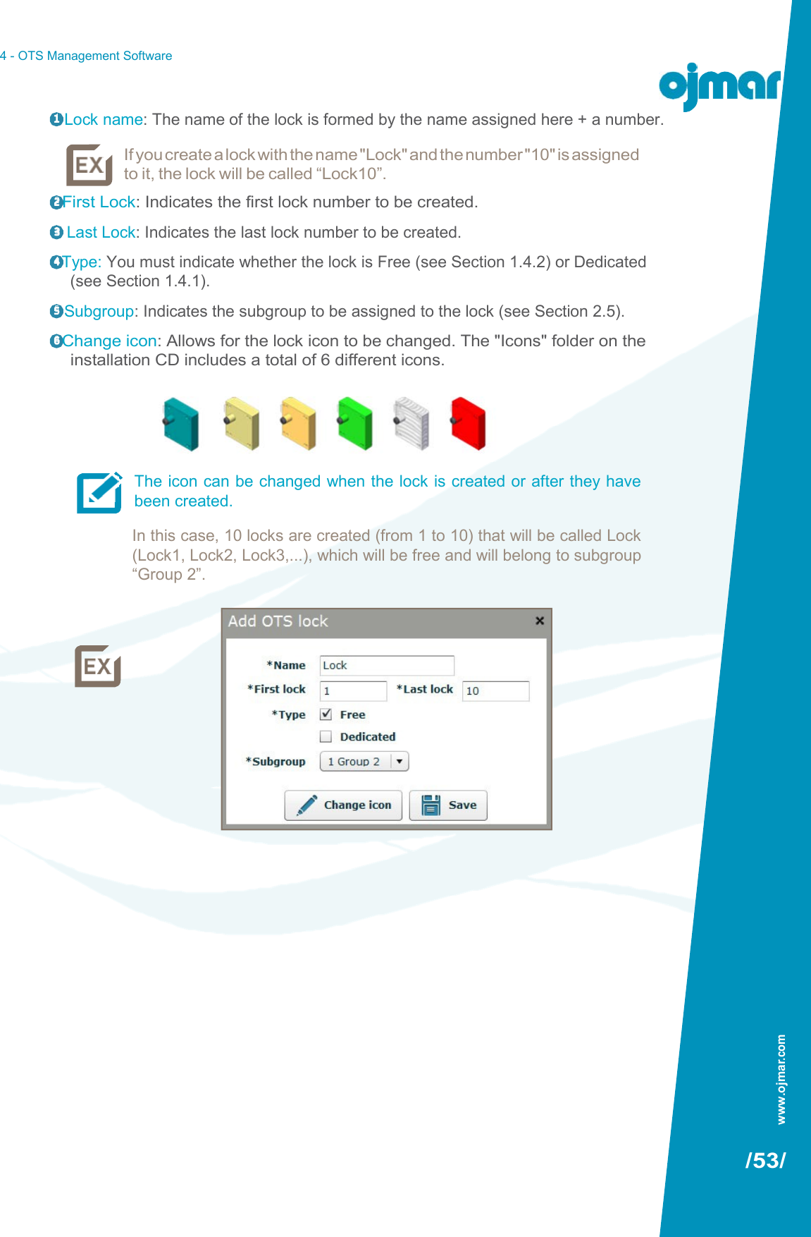
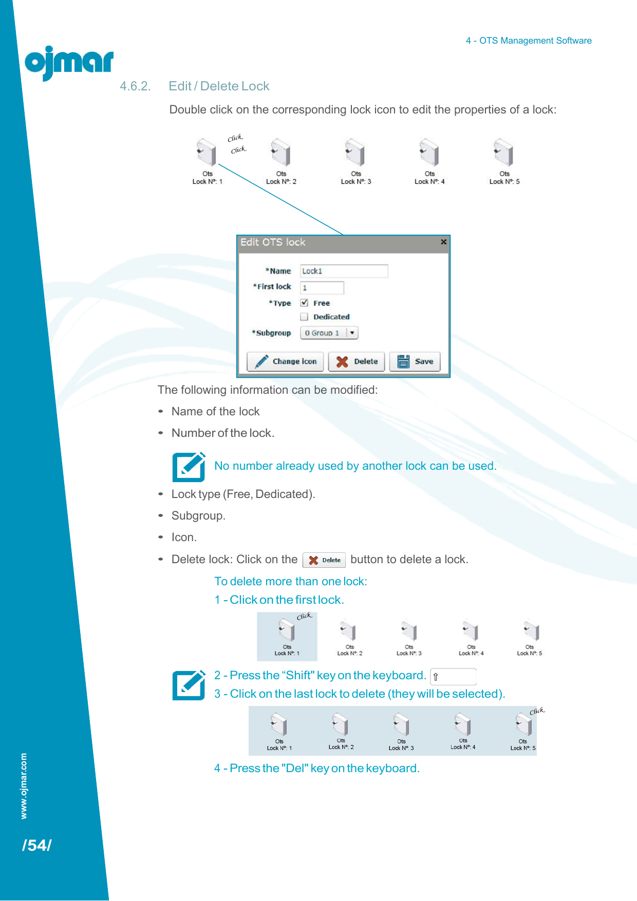
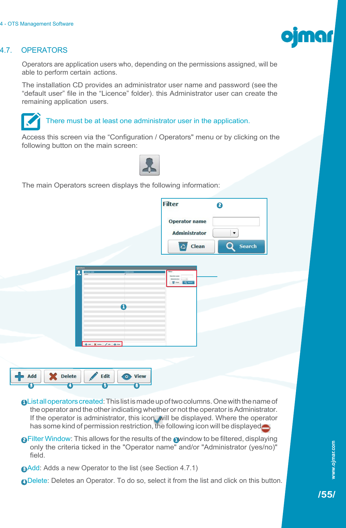
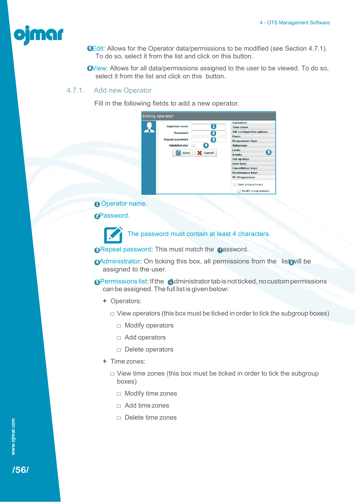
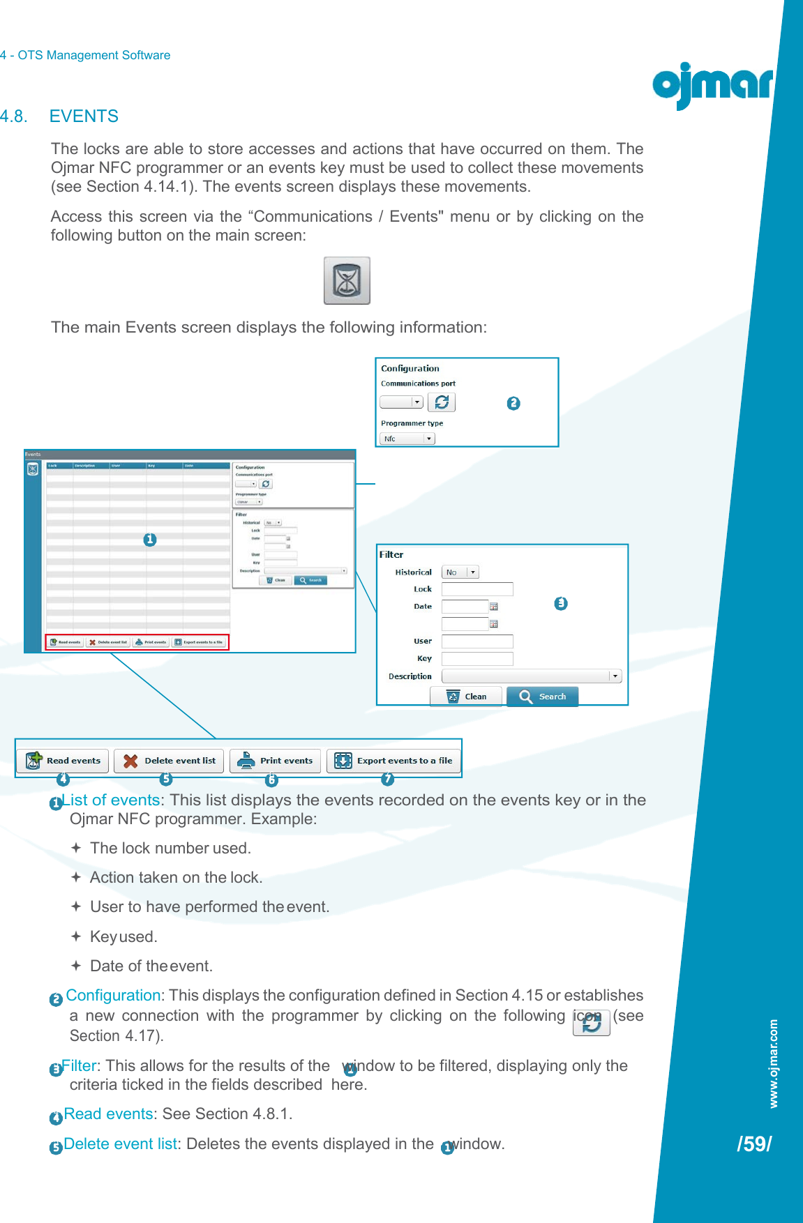
OJM001 User Manual
User manual - v2
Navigation menu
Upload a User Manual
Namespaces
Wiki Guide
HTML
PDF
Info
Views
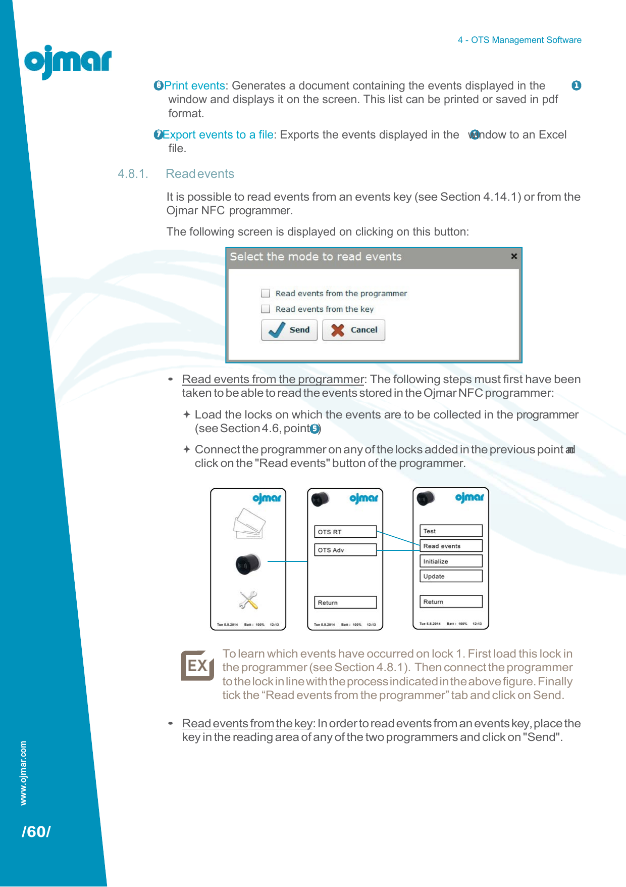
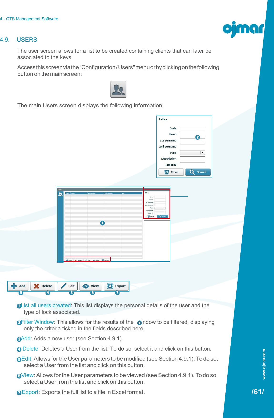
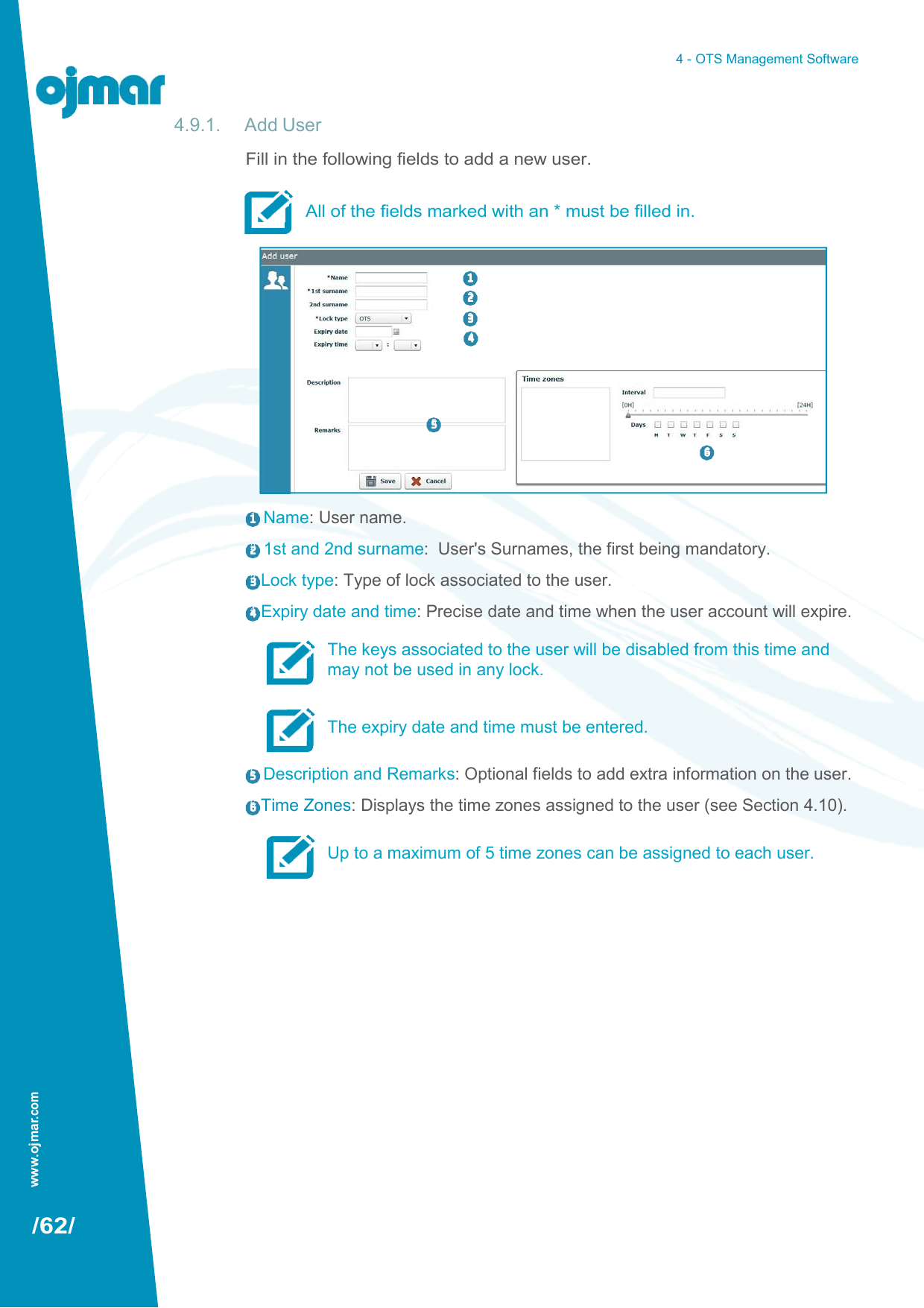
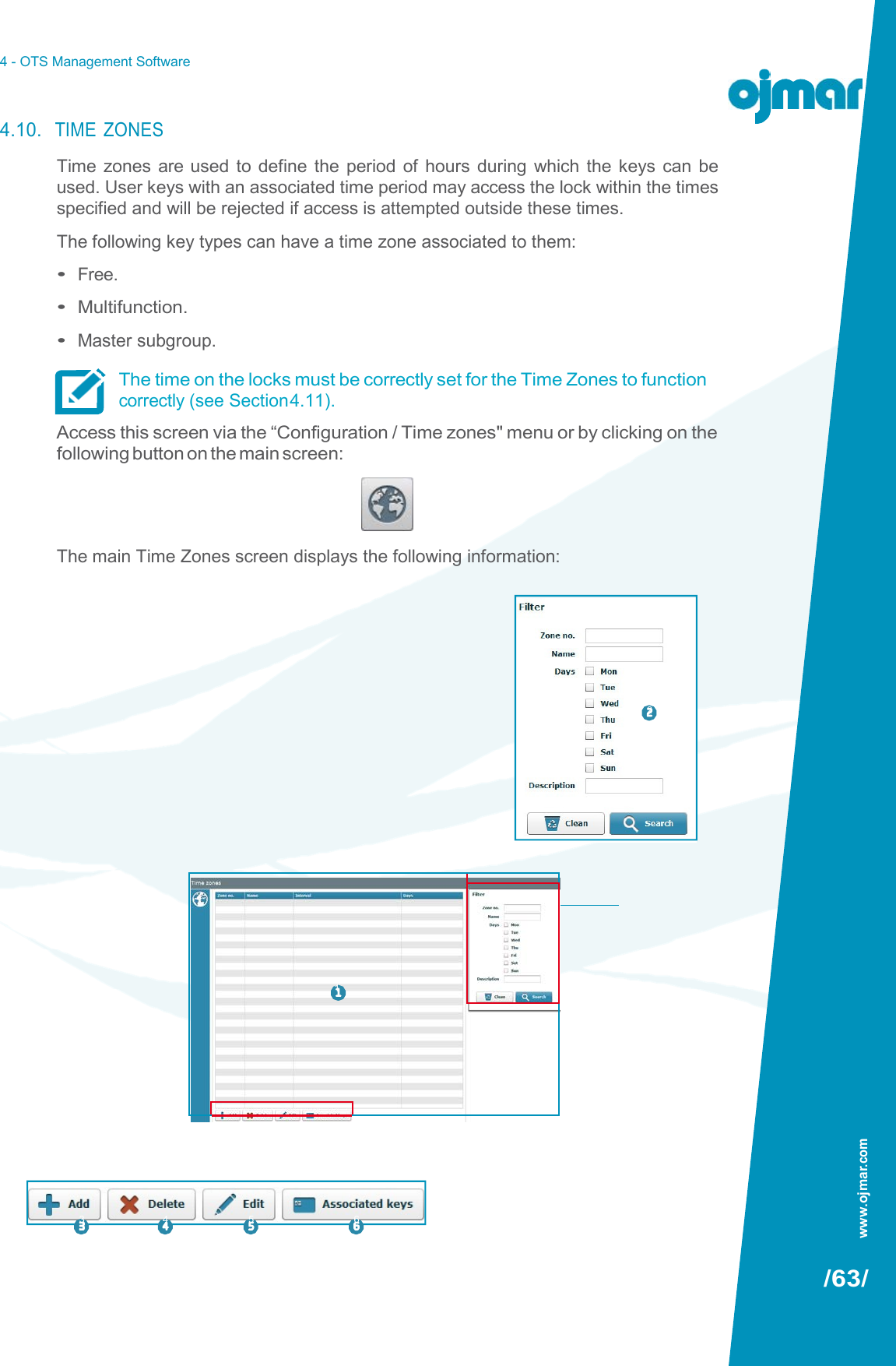
User Manual
Discussion / Help
Navigation