Novatel Wireless NRM-EG301 PCS OEM Module User Manual GPRS Technical Specifications
Novatel Wireless, Inc. PCS OEM Module GPRS Technical Specifications
Contents
- 1. Quick Start Guide
- 2. Users Manual Part I
- 3. Users Manual Part II
- 4. Revised Users manual
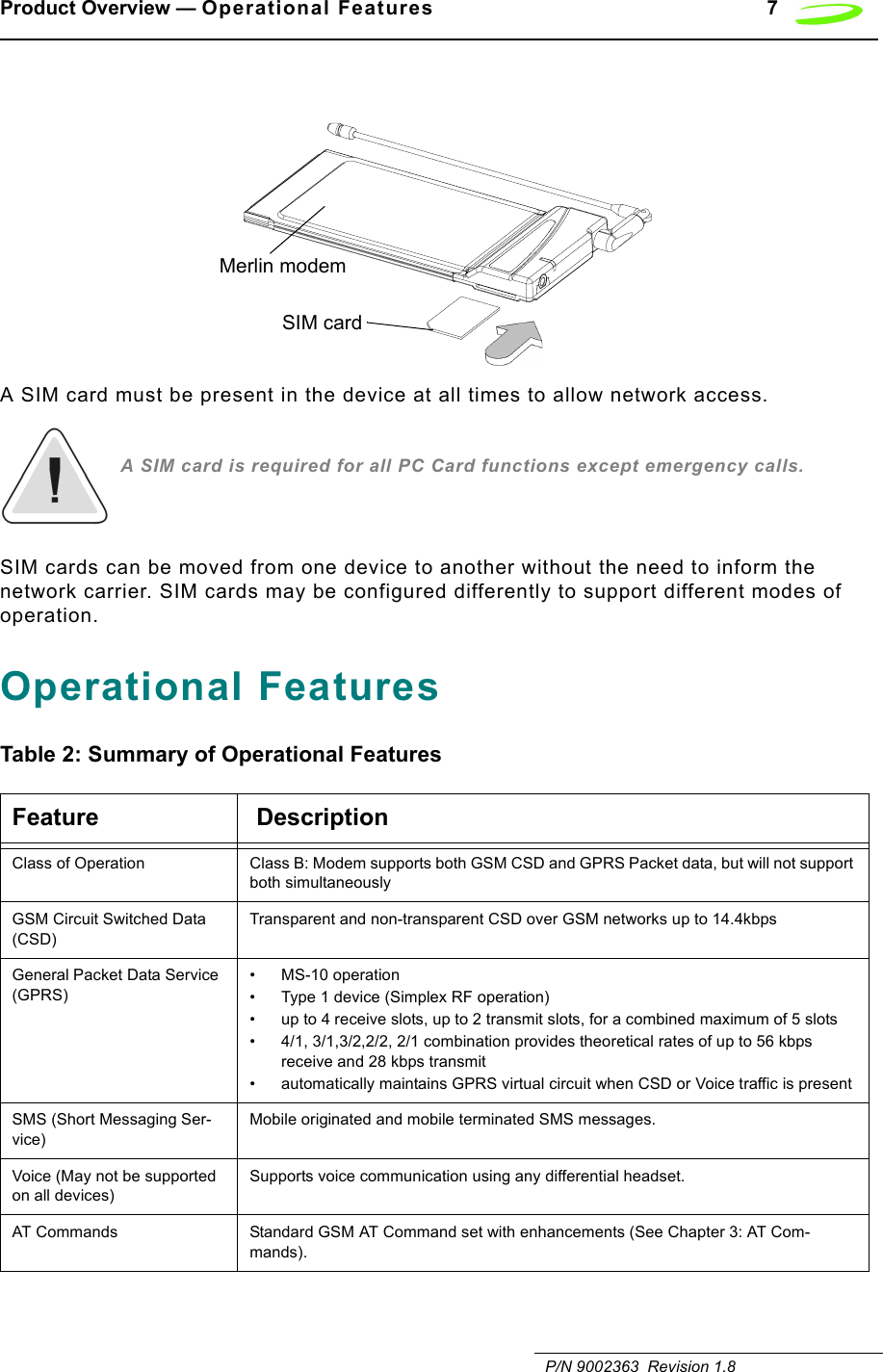
Users Manual Part I
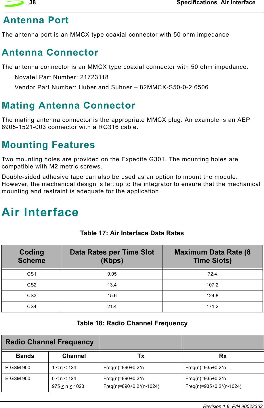
![iiRevision 1.8 P/N 90023363 Mounting Features.........................................................................................................................38Air Interface .................................................................................................................. 38Subscriber Identification Module (SIM)...................................................................... 39Modes of Operation ..................................................................................................... 40Sleep..............................................................................................................................................40SMS Messaging.............................................................................................................................40Circuit Switched .............................................................................................................................40GPRS Data ....................................................................................................................................40Standby..........................................................................................................................................41Application Information............................................................................................... 41Chapter 3: AT CommandsAT Command Set by Function .............................................................................................................44AT Command Set by Name .................................................................................................................53A/..........................................................................................................................................................53+++ .......................................................................................................................................................53ATA ......................................................................................................................................................54ATD[<n>][mgsm>] ................................................................................................................................54ATD[<mem><loc>][<mgsm>] ...............................................................................................................56ATD[<ploc>][<mgsm>] .........................................................................................................................57ATD[<str>][<mgsm>] ............................................................................................................................59ATDL ....................................................................................................................................................61ATE ......................................................................................................................................................62ATH ......................................................................................................................................................62ATI........................................................................................................................................................63ATI0......................................................................................................................................................63ATL.......................................................................................................................................................63ATM......................................................................................................................................................64ATO......................................................................................................................................................64ATP ......................................................................................................................................................65ATQ......................................................................................................................................................65ATS0 ....................................................................................................................................................66ATS2 ....................................................................................................................................................66ATS3 ....................................................................................................................................................67ATS4 ....................................................................................................................................................67ATS5 ....................................................................................................................................................68ATS6 ....................................................................................................................................................69ATS7 ....................................................................................................................................................69ATS8 ....................................................................................................................................................70ATS10 ..................................................................................................................................................70ATS12 ..................................................................................................................................................71ATT ......................................................................................................................................................71ATV ......................................................................................................................................................72ATX ......................................................................................................................................................72ATZ ......................................................................................................................................................73AT&C....................................................................................................................................................74AT&D....................................................................................................................................................74AT&F ....................................................................................................................................................74AT&V ....................................................................................................................................................75AT&W ...................................................................................................................................................76](https://usermanual.wiki/Novatel-Wireless/NRM-EG301.Users-Manual-Part-I/User-Guide-289611-Page-4.png)


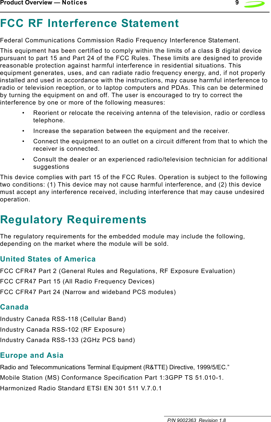


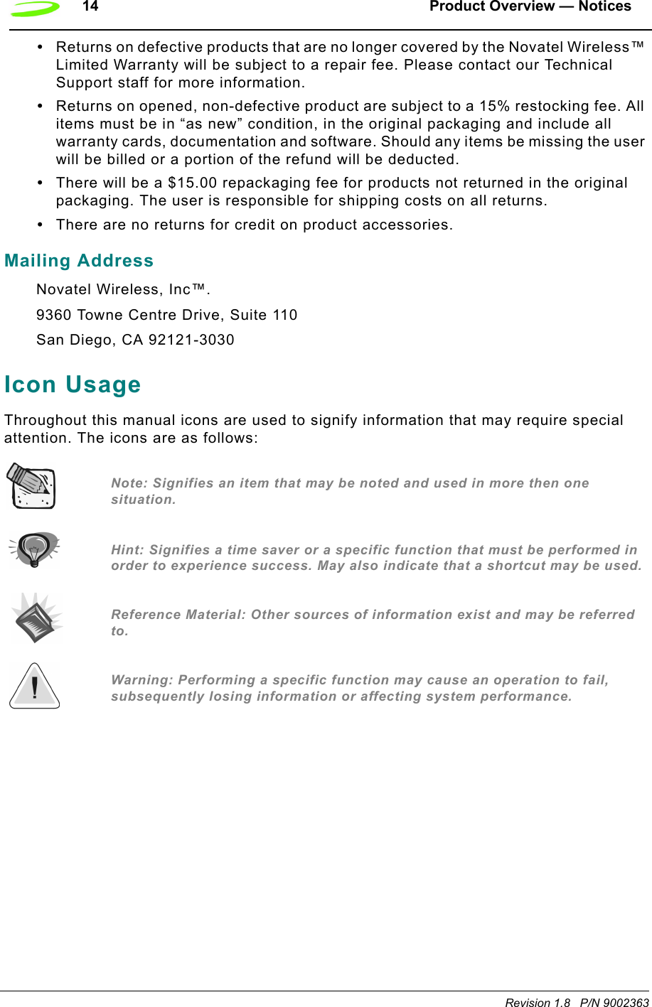

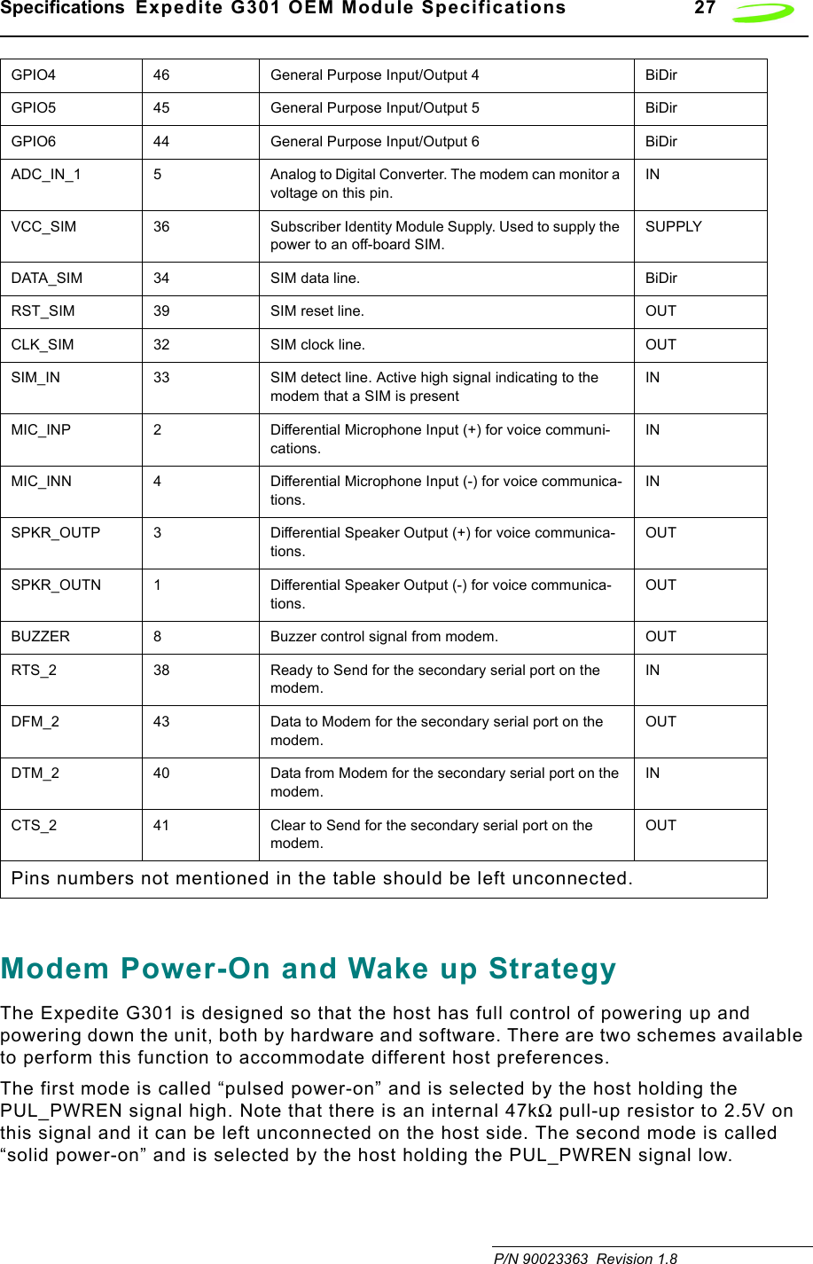
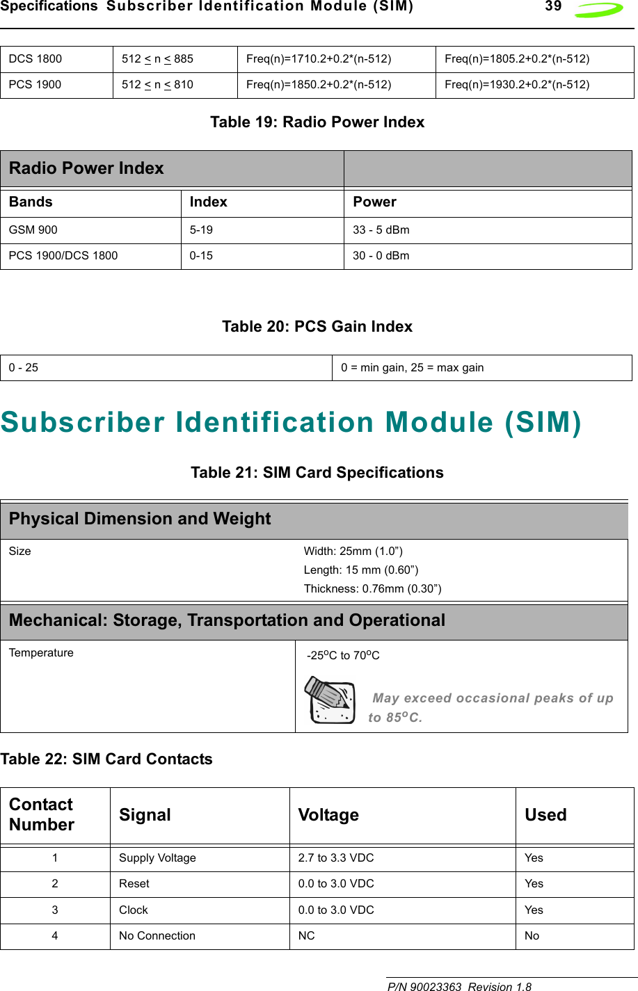

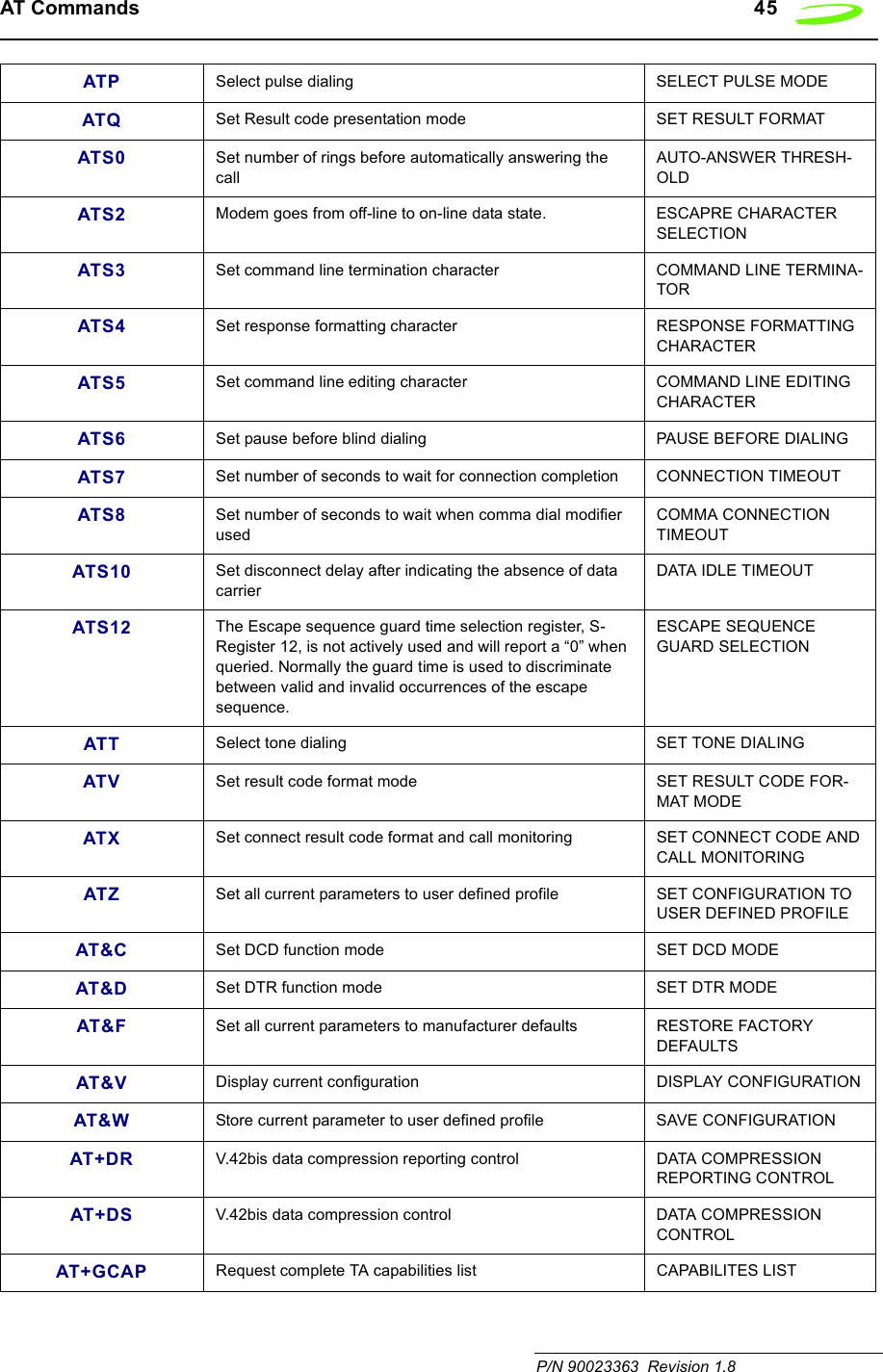
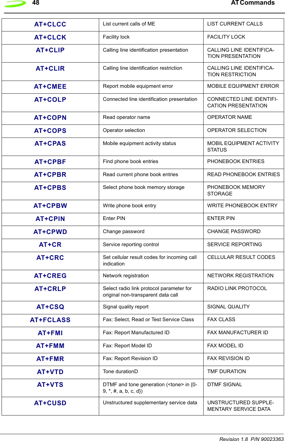
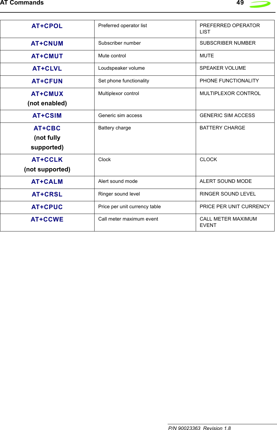
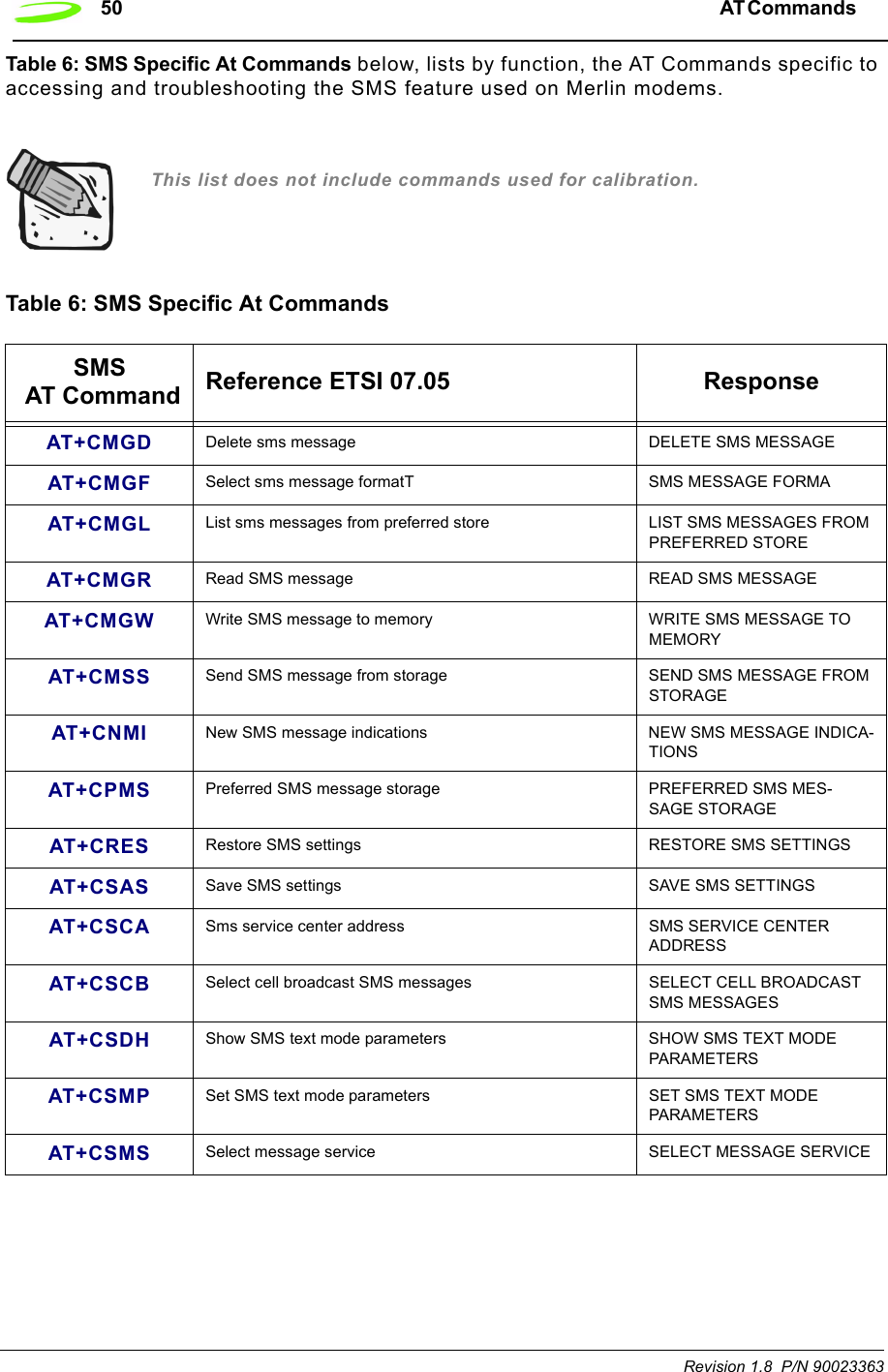
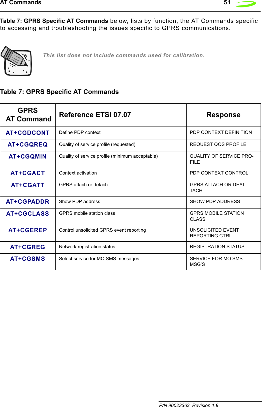
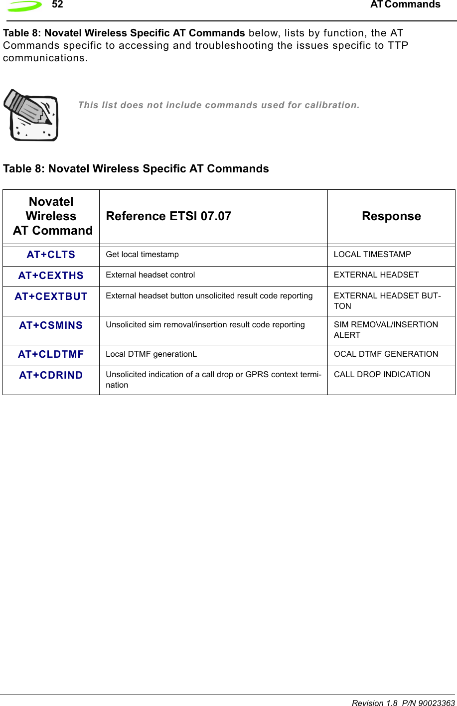
![44 AT Commands Revision 1.8 P/N 90023363AT Command Set by FunctionTable 4: Generic AT Commands below, lists by function, the generic AT Commands that can be used with Merlin modems. The general format of the command line is: <prefix><command><cr>. This list does not include commands used for calibration.Simply move the mouse over the command to link to a detailed explanation.Table 4: Generic AT CommandsGeneric AT Command Reference ETSI 07.07,PCCA STD-101 ResponseA/ Re-issues last AT command given AGAIN+++ ESC from Data mode to command mode ESCAPEATA Answer incoming call ANSWERATD[<n>][mgsm>] Mobile Originated call to dial table number DIALATD[<mem><loc>][<mgsm>]Originate call to phone number in memory <MEM>DIAL FROM MEM-ORYATD[<ploc>][<mgsm>]Originate call to phone number in current memory DIAL FROM LOCATIONATD[<str>][<mgsm>]Originate call to phone number in memory which corre-sponds to alphanumeric field <STR>DIAL USING STRINGATDL Redial last telephone number used DIAL LAST NUMBERATE Set command echo mode ECHO MODEATH Disconnect existing connection HANG-UP (DISCONNECT)ATI Display product identification information DISPLAY IDENTITYATI0 Request IMEI (International Mobile Equipment Identifier) number.IMEI: 001018-00-565563-5-00 IMEI OKATL Set monitor speaker loudness SET SPEAKER LOUDNESSATM Set monitor speaker mode SET SPEAKER MODEATO Switch from command mode to data mode OPEN DATA MODE](https://usermanual.wiki/Novatel-Wireless/NRM-EG301.Users-Manual-Part-I/User-Guide-289611-Page-52.png)
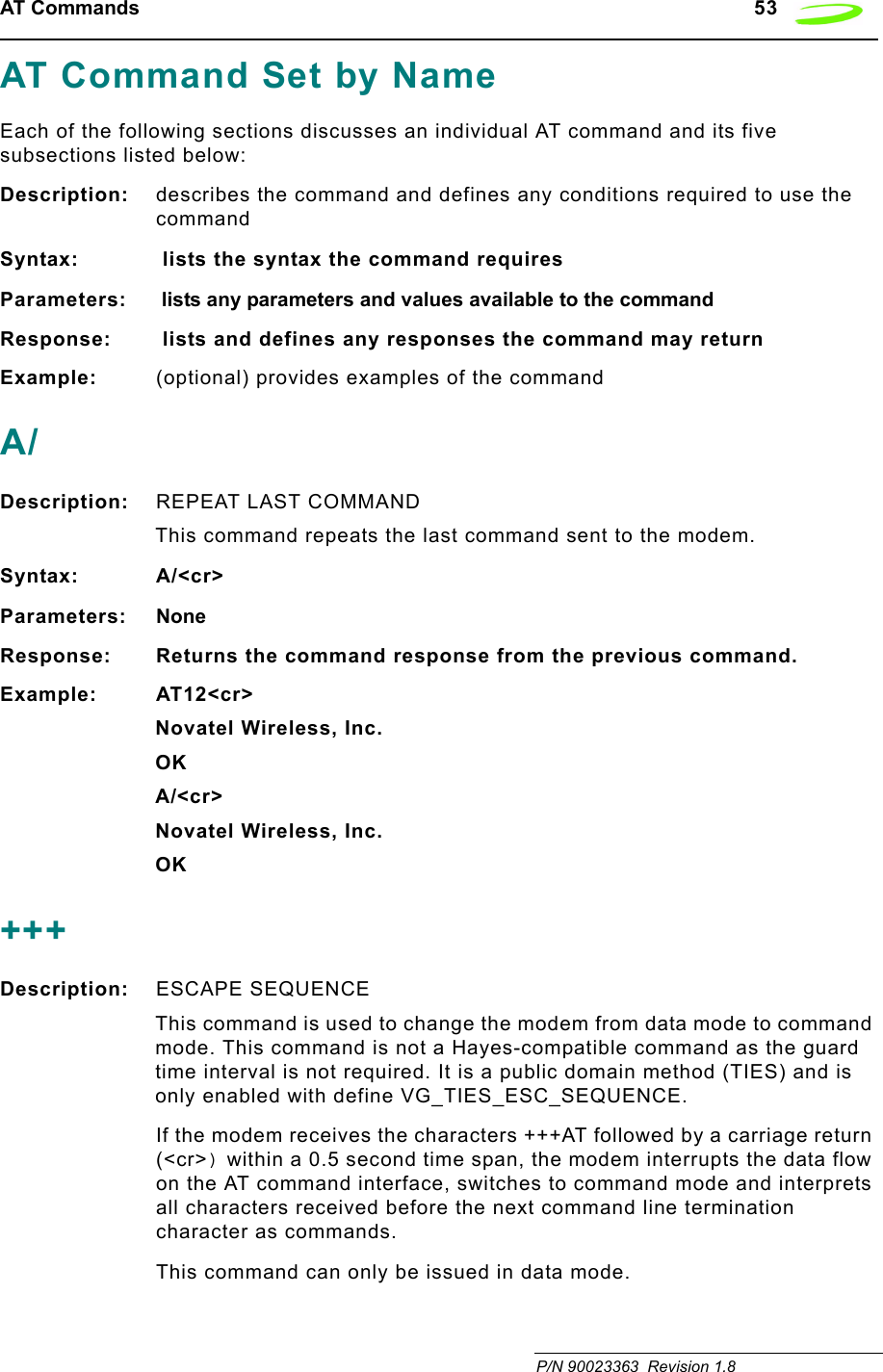
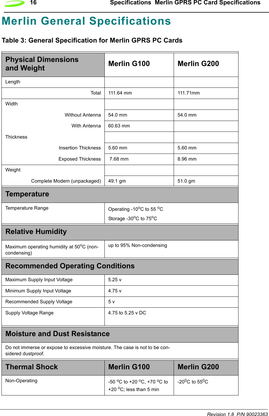
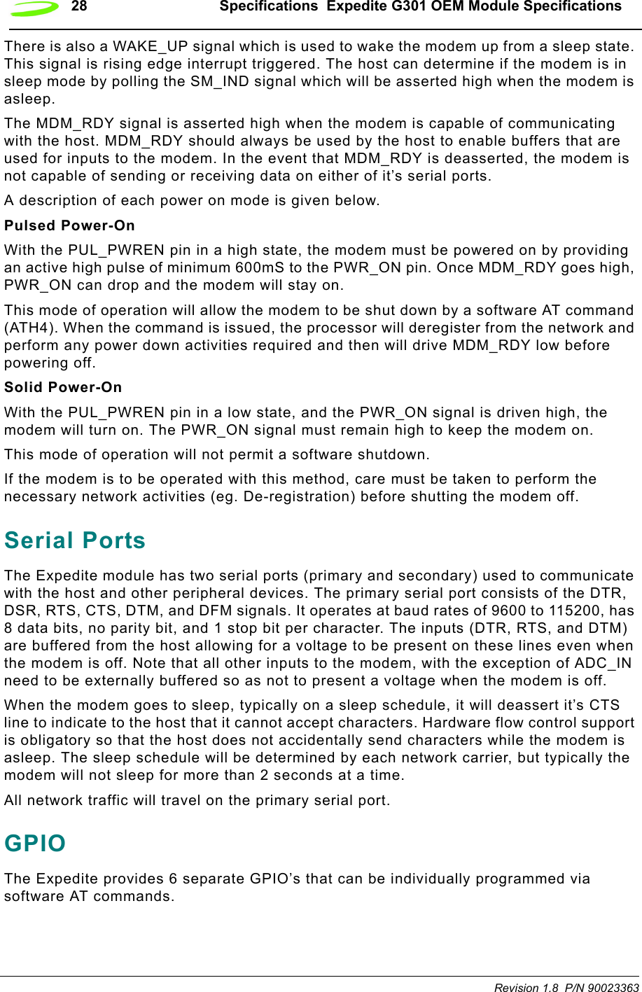
![54 AT Commands Revision 1.8 P/N 90023363This command is not a Hayes-compatible command. It is a public domain method (TIES) and is only enabled with define VG_TIES_ESC_SEQUENCE.Syntax: +++<cr>Parameters: NoneResponse: This command will return the string OK.Example: +++AT <cr>ATADescription: ANSWER This command sets the modem to answer the next call. The modem sends an off-hook signal to the remote station. Any additional commands on the same command line are ignored. The modem switches to data mode and after call is released, returns to command mode.This command can be stopped by receiving a character during execution, except during some states of connection establishment such as handshaking.Syntax: ATA<cr>Parameters: NoneResponse: If the connection is successful the modem will return the string:CONNECT<text>then switches to data mode. The <text> is only displayed if the command ATX has been set to a value greater than 0.When the modem releases the call and returns to command mode, it returns the string:OKIf no connection is made, the modem will return the string:NO CARRIERExample: ATA<cr>ATD[<n>][mgsm>]Description: DIAL NUMBERThis command will instruct the modem to originate a call to a dialable number. The modem attempts to set up an outgoing call.This command can be stopped by receiving a character during execution, except during some states of connection establishment such as handshaking.](https://usermanual.wiki/Novatel-Wireless/NRM-EG301.Users-Manual-Part-I/User-Guide-289611-Page-62.png)
![AT Commands 55 P/N 90023363 Revision 1.8 Syntax: ATD[<n>][<mgsm>]<cr>Parameters:n is the string of dialing digits and the optional V.25ter modifiers. The valid dialing digits are:0-9, * , #, +, A, B, Cand the V.25ter modifiers which are ignored:mgsm is a string of GSM modifiers, where:I is overrides the current Calling Line Identification Restriction (CLIR) setting for the callG,g displays the Closed User Group (CUG) information, set with the command +CCUG;signifies the call is a voice call and instructs the modem to return to the command mode.Response: If there is no dial tone, the modem will return the string:NO DIALTONEwhere the command ATX has been set to 2 or 4.If there is an error and it is related to the mobile equipment’s (ME) functionality, the modem will return the string:+CME ERROR: <error>If the connection is busy, the modem will return the string:BUSYwhere the command ATX has been set to 3 or 4.If the connection cannot be established, the modem will return the string:NO CARRIERIf the connection is successful and is non-voice call, the modem switches to data state and the modem will return the string:CONNECT<text>where <text> is only displayed if the command ATX has been set to a value greater than 0.If connection successful and is a voice call, the modem will return the string:OKWhen the modem releases the call and returns to command mode, it returns the string:OK](https://usermanual.wiki/Novatel-Wireless/NRM-EG301.Users-Manual-Part-I/User-Guide-289611-Page-63.png)
![56 AT Commands Revision 1.8 P/N 90023363Example:ATD9,555-1212<cr> DIAL 9, PAUSE, DIAL 5551212ATD555-1234;<cr> DIAL 5551234ATD555-09871G<cr> DIAL 5550987, OVERRIDE CLIR, DISPLAY CUGATD[<mem><loc>][<mgsm>]Description: DIAL NUMBER FROM SIM PHONE BOOK MEMORYThis command will instruct the modem to originate a call to a dialable number using reference to a number stored in the SIM’s phone book memories.Syntax: ATD[<mem><loc>][<mgsm>]Parameters:mem is the phone book at the designated memory location. There is no <mem> for emergency calls (EN). It is comprised of the following phone book parameters:FD SIM fix phone-phone bookLD SIM last-phone-phone bookDC Mobile Equipment (ME) dialed calls listON SIM (or ME) own numbers (MSISDNs) listSM SIM phone bookloc is an integer referring to a memory location that is in a range of locations available in the phone book referenced. This must be used with the mem parameter.mgsm is a string of GSM modifiers, where:I is overrides the current Calling Line Identification Restriction (CLIR) setting for the callG,g displays the Closed User Group (CUG) information, set with the command +CCUG;signifies the call is a voice call and instructs the modem to return to the command mode.Response: If there is no dial tone, the modem will return the string:NO DIALTONEwhere the command ATX has been set to 2 or 4.If there is an error and it is related to the mobile equipment’s (ME) functionality, the modem will return the string:+CME ERROR: <error>](https://usermanual.wiki/Novatel-Wireless/NRM-EG301.Users-Manual-Part-I/User-Guide-289611-Page-64.png)
![AT Commands 57 P/N 90023363 Revision 1.8 If the connection is busy, the modem will return the string:BUSYwhere the command ATX has been set to 3 or 4.If the connection cannot be established, the modem will return the string:NO CARRIERIf the connection is successful and is non-voice call, the modem switches to data state and the modem will return the string:CONNECT<text>where <text> is only displayed if the command ATX has been set to a value greater than 0.If connection successful and is a voice call, the modem will return the string:OKWhen the modem releases the call and returns to command mode, it returns the string:OKExample: ATDFD1<cr> DATA CALL TO FD PHONE BOOK ENTRY ATDLD3<cr> DATA CALL TO LD PHONE BOOK ENTRY ATDDC2I;<cr> VOICE CALL TO DC PHONE BOOK ENTRY 2 NO CLIRATD[<ploc>][<mgsm>]Description: DIAL NUMBER FROM INTERNAL MEMORYThis command will instruct the modem to originate a call to a dialable numberSyntax: ATD[<ploc>][<mgsm>]<cr>Parameters:ploc is an integer referring to a mobile equipment phone number stored at the specified location in the modem’s internal memory.mgsm is a string of GSM modifiers, where:I overrides the current Calling Line Identification Restriction (CLIR) setting for the callG,g displays the Closed User Group (CUG) information, set with the command +CCUG;signifies the call is a voice call and instructs the modem to return to the command mode.](https://usermanual.wiki/Novatel-Wireless/NRM-EG301.Users-Manual-Part-I/User-Guide-289611-Page-65.png)
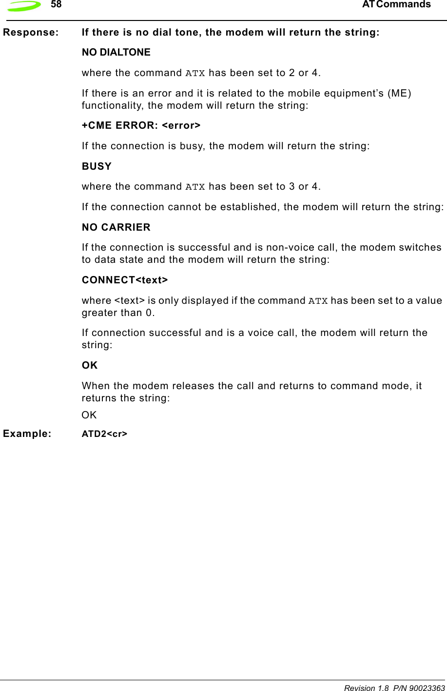
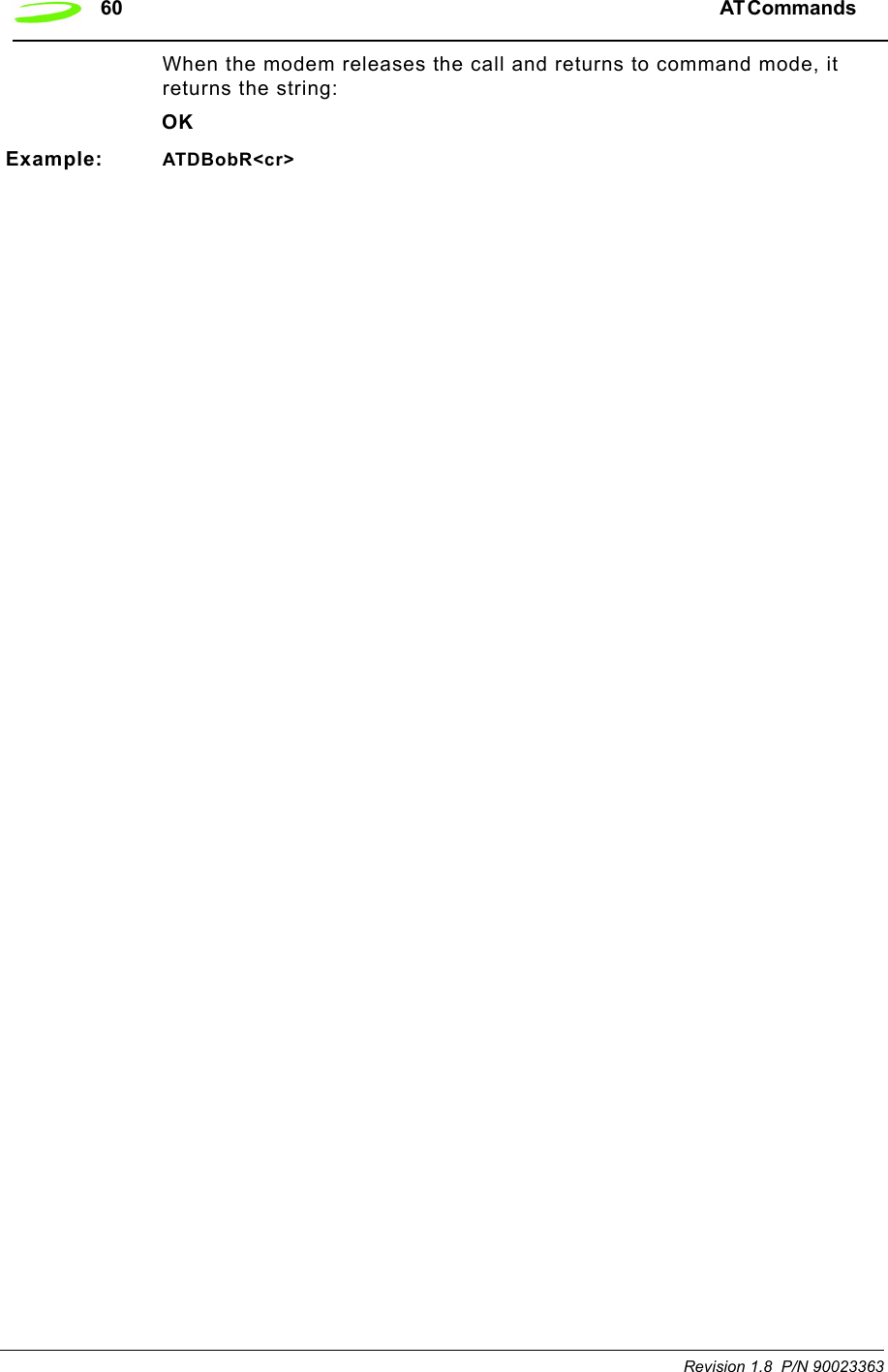
![AT Commands 59 P/N 90023363 Revision 1.8 ATD[<str>][<mgsm>]Description: DIAL NUMBR FROM NAME SEARCHThis command will instruct the modem to originate a call to a dialable number. Syntax: ATD[<str>][<mgsm>]<cr>Parameters:str is a string that is searched for in the alphanumeric fields of the phone books, located in all available memory types (i.e. SIM, Mobile Equipment Phone Book, etc.).mgsm is a string of GSM modifiers, where:I is overrides the current Calling Line Identification Restriction (CLIR) setting for the callG,g displays the Closed User Group (CUG) information, set with the command +CCUG;signifies the call is a voice call and instructs the modem to return to the command mode.Response: If there is no dial tone, the modem will return the string:NO DIALTONEwhere the command ATX has been set to 2 or 4.If there is an error and it is related to the mobile equipment’s (ME) functionality, the modem will return the string:+CME ERROR: <error>If the connection is busy, the modem will return the string:BUSYwhere the command ATX has been set to 3 or 4.If the connection cannot be established, the modem will return the string:NO CARRIERIf the connection is successful and is non-voice call, the modem switches to data state and the modem will return the string:CONNECT<text>where <text> is only displayed if the command ATX has been set to a value greater than 0.If connection successful and is a voice call, the modem will return the string:OK](https://usermanual.wiki/Novatel-Wireless/NRM-EG301.Users-Manual-Part-I/User-Guide-289611-Page-67.png)
![AT Commands 61 P/N 90023363 Revision 1.8 ATDLDescription: DIAL LAST NUMBER This command will instruct the modem to originate a call to the last telephone number used by the modem. The modem attempts to set up an outgoing call.This command can be stopped by receiving a character during execution, except during some states of connection establishment such as handshaking.Syntax: ATDL[;]Parameters: ;which signifies the call is a voice call and instructs the modem to return to the command mode.Response: If there is no dial tone, the modem will return the string:NO DIALTONEwhere the command ATX has been set to 2 or 4.If there is no last number to dial or the number is invalid, the modem will return the string:+CME ERROR: <error>If the connection is busy, the modem will return the string:BUSYwhere the command ATX has been set to 3 or 4.If the connection cannot be established, the modem will return the string:NO CARRIERIf the connection is successful and is non-voice call, the modem switches to data state and the modem will return the string:CONNECT<text>where <text> is only displayed if the command ATX has been set to a value greater than 0.If connection successful and is a voice call, the modem will return the string:OKWhen the modem releases the call and returns to command mode, it returns the string:OK](https://usermanual.wiki/Novatel-Wireless/NRM-EG301.Users-Manual-Part-I/User-Guide-289611-Page-69.png)
![62 AT Commands Revision 1.8 P/N 90023363Example: Input ResponseATDL Connect (Data Call)ATDL;(No signal given as this is a voice call)ATEDescription: ECHO MODE This command sets the echo mode of the modem, that is, whether or not the modem echoes characters received from terminal while the modem is in command mode.Syntax: ATE[<n>]Parameters: n = 0 or 10 turns echo mode off1 turns echo mode onResponse: This command will return the string OK.Example: ATE1<cr> All further data entered is ecohedOKATE0<cr> All further data entered is ecohedOKATHDescription: HANG-UP (DISCONNECT)This command instructs the modem to disconnect from the current connection and terminate the call.Syntax: ATH[0]Parameters: 0 This parameter is the default, as well as the only parameter, and does not necessarily have to be typed with the command.Response: This command will return the string OK, after the Data Carrier Detect (DCD) is turned off, if it was previously on.Example: ATH<cr> OK](https://usermanual.wiki/Novatel-Wireless/NRM-EG301.Users-Manual-Part-I/User-Guide-289611-Page-70.png)
![64 AT Commands Revision 1.8 P/N 90023363Syntax: ATL[<n>]Parameters: 0, 1, 2, 3where:0 sets the speaker volume to very low1 sets the speaker volume to low2 sets the speaker volume to medium3 sets the speaker volume to highResponse: This command will return the string OK.Example: ATL3<cr>ATMDescription: ENABLE MODEM SPEAKER This command turns the modem’s speaker circuit on or off. When the modem is installed in a computer, it will use the computer’s default speaker.This command is ignored when the modem is connected to a GSM network.Syntax: ATM[<n>]Parameters: 0, 1, 2where:0 turns the speaker off1 turns the speaker on until the modem informs the terminating equipment that a carrier has been detected2 turns the speaker on while the modem is off-hookResponse: OKExample: ATM1<cr> OKATODescription: OPEN DATA MODE This command switches the modem from command mode to data mode. This command is generally used to return the modem to data mode after the user has issued the command +++AT and worked in the modem’s command mode.Syntax: ATO[0]](https://usermanual.wiki/Novatel-Wireless/NRM-EG301.Users-Manual-Part-I/User-Guide-289611-Page-72.png)
![AT Commands 65 P/N 90023363 Revision 1.8 Parameters: 0 This parameter is the default, as well as the only parameter, and does not necessarily have to be typed with the command.Response: If connection is not successfully resumed, the modem will return the string:NO CARRIERIf connection is successfully resumed, the modem will return the string:CONNECT<text>where <text> is only displayed if the command ATX has been set to a value greater than 0.Example: ATO<cr> <Data Field to and from Modem>ATPDescription: PULSE DIAL MODE This command is used to instruct the modem to dial the next telephone number using pulse dialing. This command is a legacy command and is ignored when the modem is connected to a GSM network.Syntax: ATP<cr>Parameters: NoneResponse: This command will return the string OK.Example: ATP<cr>ATQDescription: QUIET MODE This command is used to specify whether or not the modem will sent result codes to the terminating equipment. Text sent from the modem to the terminating equipment using the ATI command will not be affected.Syntax: ATQ[<n>]Parameters: 0, 10 instructs the modem to send the result codes; this is the default.1 instructs the modem to suppress the result codes and not transmit them to the terminating equipment.Response: If this command has been set to 0, the modem’s response will be OK. If this command has been set to 1, there will be no response from the modem.Example: ATQ0<cr>](https://usermanual.wiki/Novatel-Wireless/NRM-EG301.Users-Manual-Part-I/User-Guide-289611-Page-73.png)
![66 AT Commands Revision 1.8 P/N 90023363ATS0Description: LISTEN MODE This command sets the number of rings the modem will wait before it will answer the incoming call. This command sets the modem’s S-register 0.Syntax: ATS0[=<n>][?]Parameters: =<n>, ?<n> is a number between 1 and 255 that represents the number of rings the modem will wait before answering the incoming call. This command sets the S-register 0 to the number specified in <n>. If this command is set to 0, the modem will never answer the incoming call.? will query the S-register and return the register’s current valueResponse: If the user has typed the command ATS0?, the modem will return the current value of the register and the string OK. For example:5OKIf the user has typed the command ATS0=<n>, the modem will only return the string OK.Example: ATS0=5<cr> answer after 5 ringsOKATS2Description: ESCAPE CHARACTER SELECTIONThe escape sequence consists of three repetitions of the escape code character, defined by S-Register 2 (default value: decimal 43(+)). The escape sequence causes the modem to go to the off-line command state from the on-line data state. After this escape sequence, the modem can accept user's AT Commands.Syntax: ATS2=<n><cr>Parameters: <n> is the decimal value of the ASCII character used as the “escape” characterResponse: OKExample: ATS2=43<cr> OK](https://usermanual.wiki/Novatel-Wireless/NRM-EG301.Users-Manual-Part-I/User-Guide-289611-Page-74.png)
![AT Commands 67 P/N 90023363 Revision 1.8 ATS3Description: COMMAND TERMINATION CHARACTER This command sets the character that will be used as the command line termination character. The terminating character may be changed using this command. This command sets the modem’s S-register 3.Syntax: ATS3[=<n>][?]Parameters: =<n>, ?=<n> is the ASCII code number that represents the character to be used as the command line termination character. This command sets S-register 3 to the number specified in <n>. The valid values for this parameter range from 0 to 127 and the default for this S-register is 13, which is the carriage return character.? will query the S-register and return the register’s current value.Response: If the user has typed the command ATS3?, the modem will return the current value of the register and the string OK. For example:13OKIf you the user has typed the command ATS3=<n>, the modem will only return the string OK.Example: ATS3=23<cr>ATS3?<cr>ATS4Description: EOL CHARACTER SELECTION This command sets the character that will be used as the modem’s response string end-of-line character. This command sets the modem’s S-register 4.Syntax: ATS4[=<n>][?]Parameters: =<n>, ?where:=<n> is the ASCII code number that represents the character to be used as the modem’s response string end-of-line character. This command sets S-register 4 to the number specified in <n>. The valid values for this parameter range from 0 to 127 and the default for this S-register is 10, which is the line feed character.? will query the S-register and return the register’s current value.](https://usermanual.wiki/Novatel-Wireless/NRM-EG301.Users-Manual-Part-I/User-Guide-289611-Page-75.png)
![68 AT Commands Revision 1.8 P/N 90023363Response: If the user has typed the command ATS4?, the modem will return the current value of the register and the string OK. For example:10OKIf the user has typed the command ATS4=<n>, the modem will only return the string OK.Example: ATS4=32<cr>ATS4?<cr>ATS5Description: BACKSPACE CHARACTER This command sets the character that will be used by the command line as the backspace character; when the command line receives this character, it will erase the character immediately preceding the cursor. This command sets the modem’s S-register 5.Syntax: ATS5[=<n>][?]Parameters: =<n>, ?=<n> is the ASCII code number that represents the character to be used as the backspace character. This command sets S-register 5 to the number specified in <n>. The valid values for this parameter range from 0 to 127 and the default for this S-register is 8, which is the backspace character assigned to the Backspace key on your keyboard.? will query the S-register and return the register’s current value.Response: If the user has typed the command ATS5?, the modem will return the current value of the register and the string OK. For example:8OKIf the user has typed the command ATS5=<n>, the modem will only return the string OK.Example: ATS5=110<cr>ATS5?<cr>](https://usermanual.wiki/Novatel-Wireless/NRM-EG301.Users-Manual-Part-I/User-Guide-289611-Page-76.png)
![AT Commands 69 P/N 90023363 Revision 1.8 ATS6Description: CONNECTION HOLD OFF TIMER This command sets the number of seconds the modem will wait before it will begin blind dialing (dialing without checking for a dial tone). This command sets the modem’s S-register 6.This command is ignored when the modem is connected to a GSM network.Syntax: ATS6[=<n>][?]Parameters: =<n>, ?=<n> is a number between 0 and 255 that represents the number of seconds the modem will wait before blind dialing an outbound call. This command sets S-register 6 to the number specified in <n>. The default value for this register is 2.? will query the S-register and return the register’s current value.Response: If the user has typed the command ATS6?, the modem will return the current value of the register and the string OK. For example:4OKIf the user has typed the command ATS6=<n>, the modem will only return the string OK.Example: ATS6=4<cr>ATS7Description: CONNECTION TIMEOUT This command sets the number of seconds the modem will wait for the connection to complete during an inbound or outgoing call, before it stops attempting to connect. This command sets the modem’s S-register 7.Syntax: ATS7[=<n>][?]Parameters: =<n>, ?=<n> is a number between 0 and 255 that represents the number of seconds the modem will wait before stopping the connection attempt. This command sets S-register 7 to the number specified in <n>. The default value for this register is 60.? will query the S-register and return the register’s current value.](https://usermanual.wiki/Novatel-Wireless/NRM-EG301.Users-Manual-Part-I/User-Guide-289611-Page-77.png)
![70 AT Commands Revision 1.8 P/N 90023363Response: If the user has typed the command ATS7?, the modem will return the current value of the register and the string OK. For example:4OKIf the user has typed the command ATS7=<n>, the modem will only return the string OK.Example: ATS7=4<cr>ATS8Description: COMMA DIAL MODIFIERThis command sets the value of the comma dial modifier, in seconds. The comma dial modifier is placed in-between the digits of the telephone number you wish to call to provide a pause. This might be used when dialing 9 to get an outside telephone line. This command sets the modem’s S-register 8.This command is ignored when the modem is connected to a GSM network.Syntax: ATS8[=<n>][?]Parameters: =<n>, ?=<n> is a number between 1 and 255 that represents the number of seconds the modem will wait to dial the remaining digits in the telephone number. This command sets S-register 8 to the number specified in <n>. If this command is set to 0, the there will be no pause when the comma (,) is encountered. The default is set to 2.? will query the S-register and return the register’s current value.Response: If the user has typed the command ATS8?, the modem will return the current value of the register and the string OK. For example:2OKIf the user has typed the command ATS8=<n>, the modem will only return the string OK.Example: ATS8=2<cr>ATS10Description: DATA CARRIER TIMEOUT This command sets the amount of time, in 1/10th secs, the modem will wait before returning on-hook, if it can no longer detect the data carrier. This command sets the modem’s S-register 10.](https://usermanual.wiki/Novatel-Wireless/NRM-EG301.Users-Manual-Part-I/User-Guide-289611-Page-78.png)
![AT Commands 71 P/N 90023363 Revision 1.8 Syntax: ATS10[=<n>][?]Parameters: =<n>, ?=<n> is a number between 1 and 255 that represents the number in 1/10th secs the modem will wait before going on-hook, if it no longer detects a data carrier. This command sets S-register 10 to the number specified in <n>. The default value for this register is 15.? will query the S-register and return the register’s current value.Response: If the user has typed the command ATS10?, the modem will return the current value of the register and the string OK. For example:25OKIf the user has typed the command ATS10=<n>, the modem will only return the string OK.Example: ATS10=25<cr>ATS12Description: ESCAPE SEQUENCE GUARD SELECTIONThe Escape sequence guard time selection register, S-Register 12, is not actively used and will report a “0” when queried. Normally the guard time is used to discriminate between valid and invalid occurrences of the escape sequence. The duration between escape codes must also be within the guard time. After the modem recognizes a valid escape sequence, an "OK" result code is returned. If an escape sequence is valid, the modem will exit data mode and enter command mode. The ATO command is used to go back to on-line data state.Syntax: ATS12=<n><cr>Parameters: <n> Regardless of the value entered, 0 will always be used.Response: OKExample: ATS12=10<cr>ATTDescription: TONE DIALING This command is used to instruct the modem to dial the next telephone number using tone dialing. This command is a legacy command and is ignored when the modem is connected to a GSM network.Syntax: ATT<cr>Parameters: None](https://usermanual.wiki/Novatel-Wireless/NRM-EG301.Users-Manual-Part-I/User-Guide-289611-Page-79.png)
![72 AT Commands Revision 1.8 P/N 90023363Response: This command will return the string OK.Example: ATT<cr> OKATVDescription: VERBOSE This command displays the modem’s result codes in terse or verbose form.In terse form, all result codes are represented by an error code number and all text messages have only a carriage return (<cr>) character appended to them.In verbose form, all result codes are returned as words or sentences and all text messages have a carriage return-line feed (<cr><lf>) character pair before and after the text message.Syntax: ATV[<n>]Parameters: 0, 10 will set the response format to terse1 will set the response format to verboseResponse: If the command has been set to 0, it will return the response:0If the command has been set to 1, it will return the response:OKExample: ATV=1<cr> OKATXDescription: ACCESS CONTROL This command will specify whether or not the modem will attempt to detect a dial tone and busy signal, and what type of result code is returned.Syntax: ATX[<n>]Parameters: 0, 1, 2, 3, 4where:0 will set the modem to not detect the dial tone or the busy signal and return the result code CONNECT.1 will set the modem to not detect the dial tone or the busy signal and return the result code CONNECT<additional session-specific text>.](https://usermanual.wiki/Novatel-Wireless/NRM-EG301.Users-Manual-Part-I/User-Guide-289611-Page-80.png)
![AT Commands 73 P/N 90023363 Revision 1.8 2 will set the modem to detect the dial tone, but not the busy signal. It will also return the result code CONNECT<additional session-specific text>.3 will set the modem not to detect the dial tone, but detect the busy signal. It will also return the result code CONNECT<additional session-specific text>.4 will set the modem to detect both the dial tone and the busy signal and return the result code CONNECT<additional session-specific text>.Response: This command will return the string OK.Example: ATX4<cr>ATZDescription: RESET PARAMETERS TO SAVED SETTINGS This command uses the user-defined modem settings profile stored in the non-volatile memory as the active profile. If the user-defined profile is invalid, the modem will use the factory default settings. Any additional commands on the same command line are ignored. This command uses the profile created by the AT&W command.Syntax: ATZ[0]Parameters: 0 This parameter is the default, as well as the only parameter, and does not necessarily have to be typed with the command.Response: This command will return the string OK.](https://usermanual.wiki/Novatel-Wireless/NRM-EG301.Users-Manual-Part-I/User-Guide-289611-Page-81.png)
![74 AT Commands Revision 1.8 P/N 90023363AT&CDescription: DATA CARRIER DETECT (DCD) MODE This command sets the data carrier detect mode.Syntax: AT&C[<n>]Parameters: 0, 10 sets the data carrier detect so it is always on1 sets the data carrier detect so it is only on in the presence of a data carrierResponse: This command will return the string OK.Example: AT&C1<cr>AT&DDescription: DATA TERMINAL READY (DTR) CONTROLThis command defines how the modem responds, while in data mode, to the data terminal ready (DTR) circuit changing state from ON to OFF.Syntax: AT&D[<n>]Parameters: 0, 1, 20 instructs the modem to ignore the data terminal ready state1 instructs the modem to change to command mode, while remaining connected to the call2 instructs the modem to disconnect from the call and then change to command mode. While the data terminal ready state is set to off, the modem’s auto-answer function is also off.Response: This command will return the string OK.Example: AT&D2<cr>AT&FDescription: RESTORE FACTORY DEFAULT SETTINGSThis command will return all the modem settings to their factory default setting.Syntax: AT&F[0]Parameters: 0 This parameter is the default, as well as the only parameter, and does not necessarily have to be typed with the command.Response: <cr>hello<cr><LF><LF>OKExample: AT&F0<cr>](https://usermanual.wiki/Novatel-Wireless/NRM-EG301.Users-Manual-Part-I/User-Guide-289611-Page-82.png)
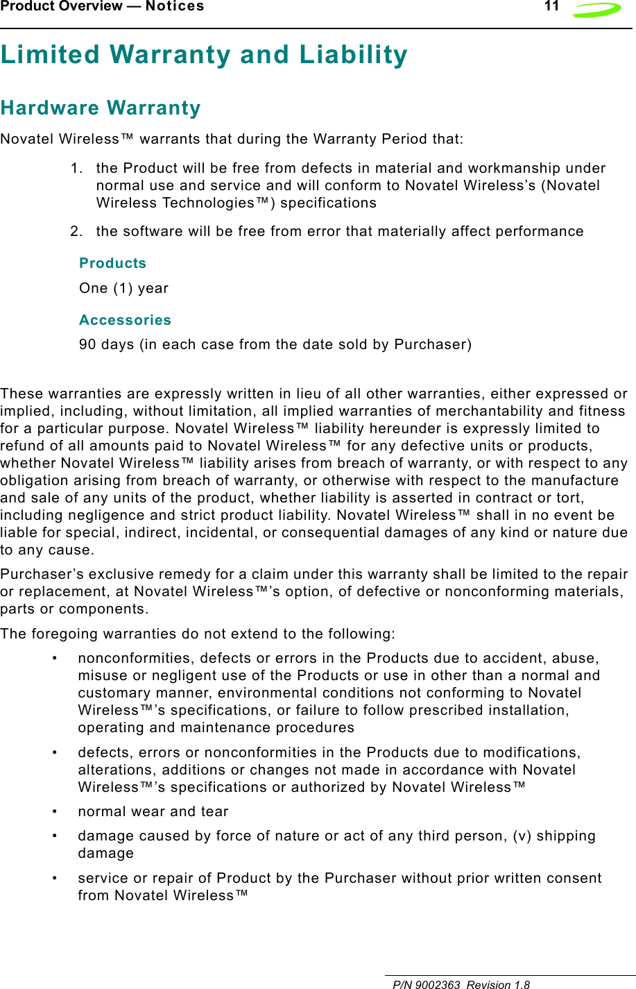
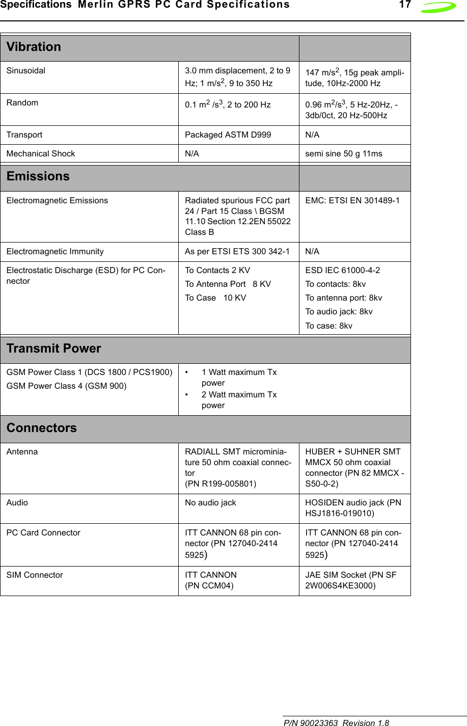
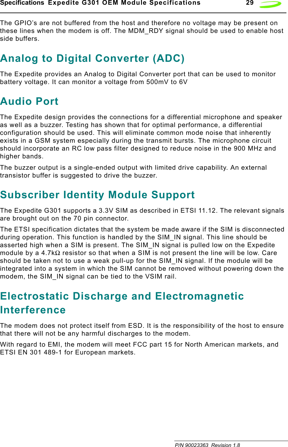
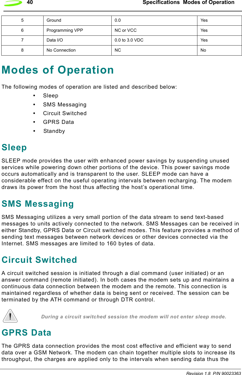
![AT Commands 75 P/N 90023363 Revision 1.8 AT&VDescription: VIEW ACTIVE PROFILE This command will display the active profile settings on the terminating equipment.Syntax: AT&V[0]Parameters: 0 This parameter is the default, as well as the only parameter, and does not necessarily have to be typed with the command.Response: The response will be a listing of the current configuration followed by the string OK. For example ACTIVE PROFILE :E1 L1 M1 Q0 V1 X4 &C1 &D2S0:0 S2:43 S3:13 S4:10 S5:8 S6:2 S7:60 S8:2 S10:15 S12:+CBST: 7,0,1+CSMS: 0+CRLP: 61,61,48,6,0,3+CRC: 0+CR: 0+FCLASS: 0+IFC: 2,2+IMODE: 0+ICF: 3,3+DR: 0+CMGF: 0+CSDH: 0+CNMI: 2,1,0,0,0+ILRR: 0+IPR: 115200+DS: 3,0,512,20+CMEE: 0+CREG: 0+CCUG: 0,0,0+CLIP: 0+COLP: 0+CCWA: 0+CAOC: 1+CLIR: 0+CSCA: "+44385016005",145+CSMP: 17,167OKExample: AT&V<cr>](https://usermanual.wiki/Novatel-Wireless/NRM-EG301.Users-Manual-Part-I/User-Guide-289611-Page-83.png)
![76 AT Commands Revision 1.8 P/N 90023363AT&WDescription: SAVE MODEM PROFILE (SETTINGS)This command stores the active modem settings profile in the modem’s non-volatile memory. This stored profile can later be retrieved using the ATZ command.Syntax: AT&W[0]Parameters: NoneResponse: This command will return the string OK.Example: AT&W0<cr>AT+CACMDescription: ACCUMULATED CALL METER (RESET OR QUERY)This command reads or resets the Advice of Charge related accumulated call meter (ACM) value in SIM file EF(ACM). ACM contains the total number of home units for both the current and preceding calls. Syntax: AT+CACM=[<password>] (Reset)Parameters: passwd SIM PIN2Response: <acm> string type; three bytes of the current ACM value in hexadecimal format (e.g. "00001E" indicates decimal value 30)Example: Input ResponseQuery AT+CACM? 00037FReset AT+CACM=opensesame OKTe s t AT+CACM=? OKAT+CALMDescription: ALERT SOUND MODEThis command sets the sound actions to to alert the user. This can be used to enable or disable the sound utilized to alert the user. Available in Command mode only.Syntax: AT+CALM=<mode>Parameters: 0 Normal Mode<mode> 0 normal mode1 silent mode (all sounds from ME are prevented)Response: OK](https://usermanual.wiki/Novatel-Wireless/NRM-EG301.Users-Manual-Part-I/User-Guide-289611-Page-84.png)
![AT Commands 77 P/N 90023363 Revision 1.8 Example:Query +CALM: <mode>+CME ERROR: <err>Tes t +CALM: (list of supported <mode>s)+CME ERROR: <err>AT+CAMMDescription: ACCUMULATED CALL METER MAXIMUMThis command sets the Advice of Charge related accumulated call meter maximum value in SIM file EF(ACMmax). ACMmax contains the maximum number of home units allowed to be consumed by the subscriber.Syntax: AT+CAMM=[<ACMMAX>[,<PASSWD>]]Parameters: ACMMAX string type; three bytes, 000001-FFFFFF, of the max. ACM value in hexa-decimal format (e.g. "00001E" indicates decimal value 30). A value of 000000 will disable ACMmax feature.PASSWD SIM PIN2Example: Input ResponseQuery AT+CAMM? 00037FSet AT+CAMM=000400 OKTes t AT+CAMM=? OKAT+CAOCDescription: ADVICE OF CHANGEThis command, when active, sends an unsolicited result code when the current call meter (CCM) value changes, this will not be reported more than once every 10 secs.Syntax: AT+CAOC=<mode>Parameters: 0, 10query CCM value1 deactivate the unsolicited reporting of CCM value2 activate the unsolicited reporting of CCM valueExample: Input ResponseQuery AT+CAOC? Current mode OKSet AT+CAOC=1 OKTes t AT+CAOC=? List of possible selectIons](https://usermanual.wiki/Novatel-Wireless/NRM-EG301.Users-Manual-Part-I/User-Guide-289611-Page-85.png)
![AT Commands 79 P/N 90023363 Revision 1.8 AT+CBSTDescription: Bearer Service TypeThis command selects the bearer service <name> with data rate <speed>, and the connection element <ce> to be used when data calls are originated.Syntax: AT+CBST=[<speed>] [,<name>[,<ce>]]]Parameters:<speed> 0 autobalancing1 300 bps (V.21)2 1200 bps(V.22)3 1200/75 bps (V.23)4 2400 bps (V22bis)5 2400 bps(V.26ter)6 4800 bps(V.32)7 9600 bps (V.32)12 9600 bps (V.34)14 14400 bps (V.34)65 300 bps (V.110)66 1200 bps (V.110 or X.31 flag stuffing)68 2400 bps (V.110 or X.31 flag stuffing)70 4800 bps (V.110 or X.31 flag stuffing)71 9600 bps (V.110 or X.31 flag stuffing)75 14400 bps (V.110 or X.31 flag stuffing)<name> 0 asynchronous modem2 PAD access (asynchronous)<ce> 0 transparent1 non-transparentExample: Query ResponseQuery AT+CBST? Current mode OKSet AT+CBST=7,2,0 OKTes t AT+CBST=? List of possible selectIon](https://usermanual.wiki/Novatel-Wireless/NRM-EG301.Users-Manual-Part-I/User-Guide-289611-Page-87.png)
![80 AT Commands Revision 1.8 P/N 90023363AT+CCFCDescription: CALL FORWARDThis command controls the call forwarding supplementary service. Registration, erasure, activation, deactivation, and status query are supported. Only <reas> and <mode> should be entered with mode (0-2,4).Syntax: AT+CCFC = <reas>, <mode>[, <number> [, <type> [,<class> [, <subaddr> [,<satype> [,<time>]]]]]]Parameters:<reas> 0 unconditional1 mobile busy2 no reply3 not reachable4 all call forwarding (0-3)5 all conditional call forwarding (1-3)<mode> 0 disable1 enable2 query status3registration4 erasure<number> string type phone number of forwarding address in format specified by <type> asynchronous modem<type> type of address in integer format; default 145 when dialing string includes international access code character "+", otherwise 129<subaddr> string type subaddress of format specified by <satype><satype> type of subaddress in integer; default 128<class> 1 voice2data4fax7all classes<time> time, rounded to a multiple of 5 secs](https://usermanual.wiki/Novatel-Wireless/NRM-EG301.Users-Manual-Part-I/User-Guide-289611-Page-88.png)
![AT Commands 81 P/N 90023363 Revision 1.8 <status> 0 not active1activeResponse: If <mode><>2 and command successfulOKIf there is a network error:+CCFC: 0, 0If <mode>=2 and command successful (only in connection with <reas> 0 – 3)For registered call forward numbers:+CCFC: <status>, <class1>[, <number>, <type> [, <time>]] [<cr><LF>+CCFC: ....] OKIf no call forward numbers are registered (and therefore all classes are inactive):+CCFC: <status>, <class> OKwhere <status>=0 and <class>=7If error is related to ME functionality:+CME ERROR: <err>Example: Input OutputQuery AT+CCFC? Current mode OKSet AT+CCFC=0,1,,,,,, OKTes t AT+CCFC=? List of possible selectIonAT+CCLKDescription: CLOCK SETTING, TIME OF DAY, DATEThis command is used to set the local time for the device as well as determining the current time. ME does not support time zone indication.Syntax: AT+CCLK=<time>Parameters:<time> string type value; format is "yy/MM/dd,hh:mm:ss”; where characters indicate year (two last digits), month, day, hour, minutes and seconds. e.i 22:10:00 GMT equals to "94/05/06,22:10:00"](https://usermanual.wiki/Novatel-Wireless/NRM-EG301.Users-Manual-Part-I/User-Guide-289611-Page-89.png)
![82 AT Commands Revision 1.8 P/N 90023363Response:Query +CCLK: <time>+CME ERROR: <err>Te s t OKAT+CCUGDescription: CLOSER USER GROUP This command sets the Closed User Group supplementary service parameters as a default adjustment for all following calls.Syntax: AT+CCUG=[<n>] [,<index>[,<info>]]]Parameters:<speed> 0disable CUG1 enable CUG71 9600 bps (V.110 or X.31 flag stuffing)<index> 0...9 CUG index10 no index (preferred CUG taken from subscriber data)<info> 0 no information1 suppress OA (Outgoing Access)2 suppress preferential CUG3 suppress OA and preferential CUGResponse: +CCUG: <n>,<index>,<info> OKIf error is related to ME functionality:+CME ERROR: <err>Example: Input OutputQuery AT+CCUG? Current mode OKSet AT+CCUG=0,1,,,,,, OKTe s t AT+CCUG=? List of possible selectionsAT+CCWADescription: CALL WAITINGThis command controls the Call Waiting supplementary service. Activation, deactivation and status query are supported.Syntax: AT+CCWA=[<n>] [,<mode>[,<class>]]]Parameters:](https://usermanual.wiki/Novatel-Wireless/NRM-EG301.Users-Manual-Part-I/User-Guide-289611-Page-90.png)
![AT Commands 83 P/N 90023363 Revision 1.8 Parameters:<n> 0 disable unsolicited result code 1 enable presentation of an unsolicited result code71 9600 bps (V.110 or X.31 flag stuffing)<mode> when <mode> parameter not given, network is not interrogated0disable1 enable2 query status<class> is a sum of integers each representing a class of information1 voice (telephony)2 data (bearer service)4 fax (teleservice)7 default (equals to all classes)<status> 0 not active1 enableExample: Input OutputQuery AT+CCWA? Current selection OKSet AT+CCWA=1,1,1,1 OKTes t AT+CCWA=? List of possible selectionsUnsolicited Response: When the presentation Call Waiting at the MODEM is enabled (and Call Waiting is enabled) and a terminating call set up has attempted during an established call, an unsolicited result code is returned:+CCWA: <number>,<type>,<class>[,<alpha>]<number> string type phone number of calling address in format specified by <type><type> type of address octet in integer format; 145 when dialing string includes international access code character "+", otherwise 129<alpha> optional string type alphanumeric representation of <number> corresponding to the entry found in a phone book](https://usermanual.wiki/Novatel-Wireless/NRM-EG301.Users-Manual-Part-I/User-Guide-289611-Page-91.png)
![86 AT Commands Revision 1.8 P/N 90023363AT+CEXTHS Description: EXTERNAL HEADSET This command sets the alert mechanism and also permits polling for the current state of the headset jack, either present or absent.Syntax: AT+CEXTHS=<n>Parameters:<n> 0 Disable unsolicited result code1 Enable unsolicited result codeResponse: OKStatus Query Response +CEXTHS: <n>,<attach><n> 0 Unsolicited result code disabled1 Unsolicited result code enabled<attach> 0 unattached external headset1 attached external headsetUnsolicited result code: +CEXTHS: <attach>Query AT+CEXTHS? Current selection OKTest AT+CEXTHS=? List of possible selectionsSet AT+CEXTHS=0 OKAT+CFUNDescription: SET FUNCTIONALITY LEVELSets the current functionality of the device. Typically used on phones and voice applications. Support for this command will be hardware dependant. For UPGRADE_SYSTEM_2, settings above 1 are not supported.Syntax: AT+CFUN=<fun>[,<rst>]Parameters:<fun> 0 minimum functionality1 full functionality (Default)2 disable phone transmit RF circuits only3 disable phone receive RF circuits only4 disable phone both transmit and receive RF circuits5..127 reserved for manufacturers as intermediate states between full and minimum functionality<rst> 0 do not reset the ME before setting it to <fun> power level](https://usermanual.wiki/Novatel-Wireless/NRM-EG301.Users-Manual-Part-I/User-Guide-289611-Page-94.png)
![AT Commands 87 P/N 90023363 Revision 1.8 Response:Query AT+CFUN? Current selection OKTest AT+CFUN=? List of possible selectionsSet AT+CFUN=1 OKAT+CGACTDescription: PDP CONTEXT ACTIVATE / DEACTIVATEThis execution command is used to activate or deactivate the specified PDP context(s).Syntax: AT+CGACT=[<state>[,<cid>[,<cid>[,…]]]]Parameters:<cid> a numeric parameter which specifies a particular PDP context definition (see +CGDCONT command). The following parameters are defined in GSM 03.60 -<state> indicates the state of PDP context activation0 – deactivated1 – activatedOther values are reserved and will result in an ERROR response to the execution command.Response: AT+CGACT?+CGACT: <cid>,<state>[<cr><LF>+CGACT: <cid>,<state>[…]]AT+CGAPNRThis command reads APNs from the store. The command can be provided with an absolute APN index to read or an index range for a group of APNs to fetch.Description: Read records from the APN store.Syntax: AT+CGAPNR:<index1>,[<index2>]Parameters: <index1> index of APN record to read or start index of read list<index2> stop index of record listResponse: User specifies index of record to read or range of records to display. Returns the data contained within the specified APN record(s). Entries that are invalid are not shown.+CGAPNR:<index>,<apn>,<usage>,<description>,<user>,<password>,OKExample: AT+CGAPNR=<index1>,[<index2>]Test: AT+CGAPNR=? Returns the parameter for the read operation.](https://usermanual.wiki/Novatel-Wireless/NRM-EG301.Users-Manual-Part-I/User-Guide-289611-Page-95.png)
![88 AT Commands Revision 1.8 P/N 90023363AT+CGAPNWThis command writes or deletes an APN specified by a given index number. The user provides the description of the APN to write. The minimum description features an index in the case of a delete event or an index and an APN in the case of a write event.Description: Write/delete record from the APN store.Syntax: AT+CGAPNW:<index>[<apn>,[<....>]]Parameters: <index> index of APN records to read<apn> APN string<usage> usage for this APN (1=General IP, 2=WAP)<description> description string<user> user name string<password> password stringResponse: Writes supplied data to the specified APN record in the store. If only the index field is supplied, the specified record is deleted.OKA CME error if the index is invalid or entered data is invalid:+CME ERROR:invalid indexERROR+CME ERROR: invalid input value. ERRORExample: AT+CGAPNW:<index>[<apn>,[<usage>,[<description>[<user>,<password>]]]]]](https://usermanual.wiki/Novatel-Wireless/NRM-EG301.Users-Manual-Part-I/User-Guide-289611-Page-96.png)
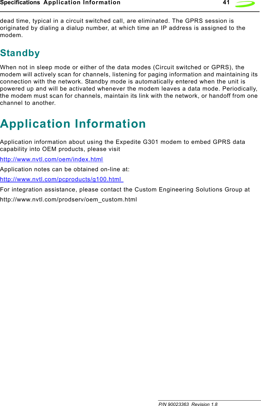
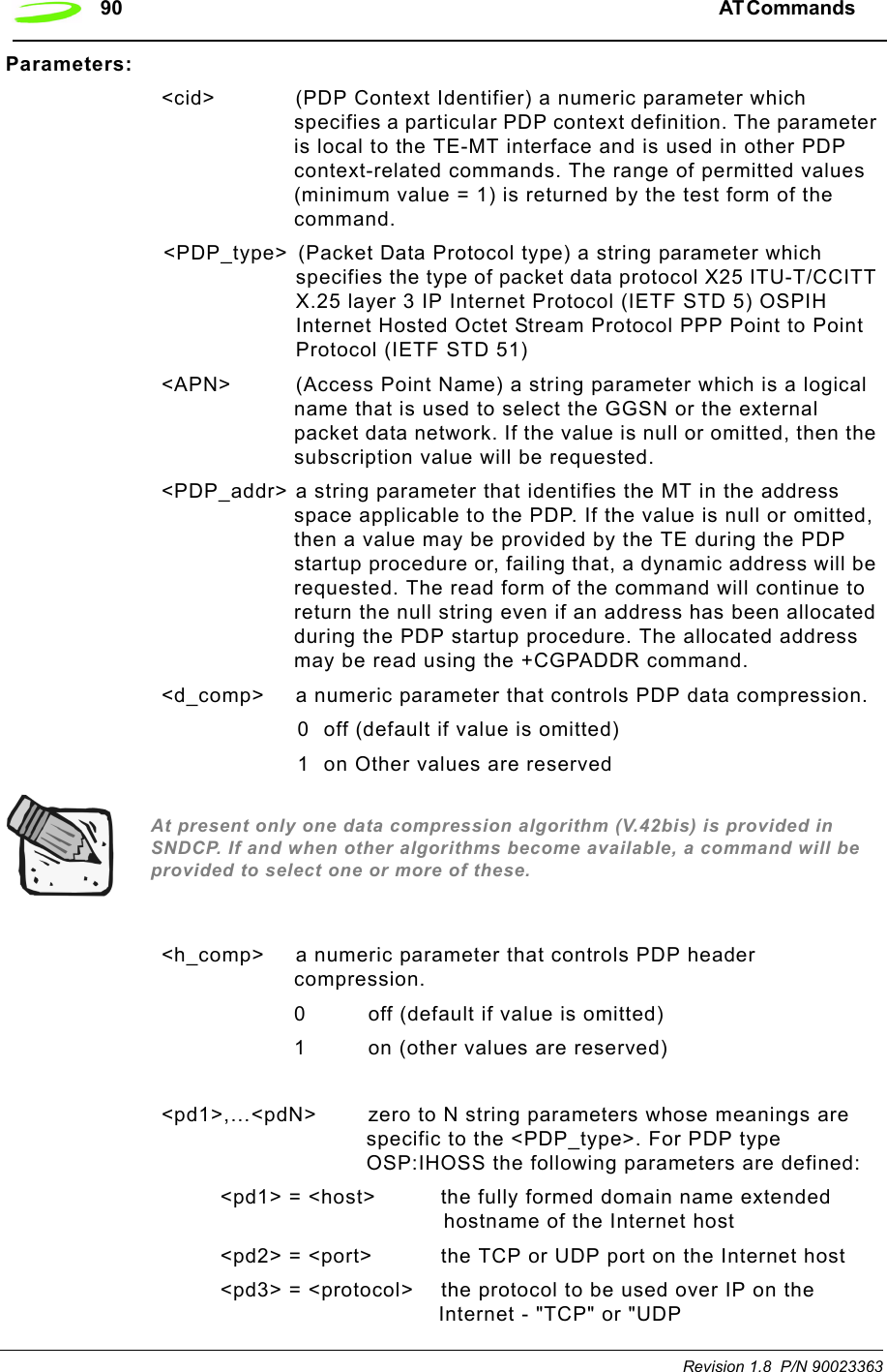
![AT Commands 89 P/N 90023363 Revision 1.8 AT+CGATTDescription: GPRS ATTACHED OR DEATTACHEDThis execution command is used to attach to, or detach the MT from, the GPRS service.Syntax: AT+CGATT= [<state>]Parameters: <state> indicates the GPRS attach state0 – attached1 – detachedOther values are reserved and will result in an ERROR response to the execution command.Response: +CGATT:<state>Query AT+CGATT? OKTest AT+CGATT=?Set AT+CGATT=0AT+CGCLASSDescription: GPRS MOBILE STATION CLASSClass A and B are not supported by this GPRS solution. Class C is only supported for <class> values of “CG” and “CC”Syntax: AT+CGCLASS= [<class>]Parameters: <class> a string parameter which indicates the GPRS mobile class (in descending order of functionality)A class A (highest)Bclass BCG class C in GPRS only modeCC class C in circuit switched only mode (lowest)Response: +CGCLASS: <class>AT+CGDCONTDescription: PDP CONTEXT DEFINEDThis set command specifies PDP context parameter values for a PDP context identified by the (local) context identification parameter <cid>.Define the PDP context and APN address.Syntax: AT+CGDCONT=[<cid>[,<PDP_type>[,<APN>[,<PDP_addr>[,<d_comp>[,<h_comp>[,<pd1>[,…[,pdN]]]]]]]]]](https://usermanual.wiki/Novatel-Wireless/NRM-EG301.Users-Manual-Part-I/User-Guide-289611-Page-97.png)
![AT Commands 91 P/N 90023363 Revision 1.8 Example: AT+CGDCONT? +CGDCONT: <cid>,<PDP_type>,<APN>,<PDP_addr>,<data_comp>,<head_comp>[,<pd1>[,…[,pdN]]] [<cr><LF>+CGDCONT: <cid>,<PDP_type>,<APN>,<PDP_addr>,<data_comp>,<head_comp>[,<pd1>[,…[,pdN]]] AT+CGEREPDescription: UNSOLICITED EVENT REPORTING CONTROLSyntax: AT+CGEREP=[<mode>[,<bfr>]]Parameters:<mode> 0 buffer unsolicited result codes in the MT; if MT result code buffer is full, the oldest ones can be discarded. No codes are forwarded to the TE.1 discard unsolicited result codes when MT-TE link is reserved (e.g. in online data mode); otherwise forward them directly to the TE2 buffer unsolicited result codes in the MT when MT?TE link is reserved (e.g. in online data mode) and flush them to the TE when MT-TE link becomes available; otherwise forward them directly to the TE<bfr> 0 MT buffer of unsolicited result codes defined within this command is cleared when <mode> 1 or 2 is entered1 MT buffer of unsolicited result codes defined within this command is flushed to the TE when <mode> 1 or 2 is entered (OK response shall be given before flushing the codes)Unsolicited Response:+CGEV: NW DEACT <PDP_type>,<PDP_addr>[,<cid>]+CGEV: ME DEACT <PDP_type>,<PDP_addr>[,<cid>]+CGEV: NW DETACH+CGEV: ME DETACH+CGEV: ME CLASS <class><PDP_type>Packet Data Protocol type (see +CGDCONT command)<PDP_addr>Packet Data Protocol address (see +CGDCONT command}<cid> Context Id (see +CGDCONT command). Note: <cid> only given if known to the MT.<class> GPRS mobile class (see +CGCLASS command)Query AT+CGEREP? OK](https://usermanual.wiki/Novatel-Wireless/NRM-EG301.Users-Manual-Part-I/User-Guide-289611-Page-99.png)