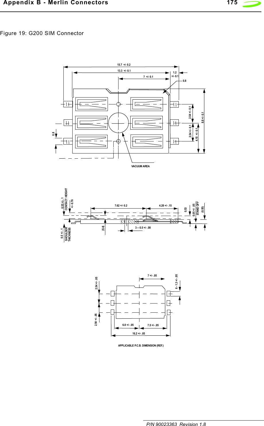
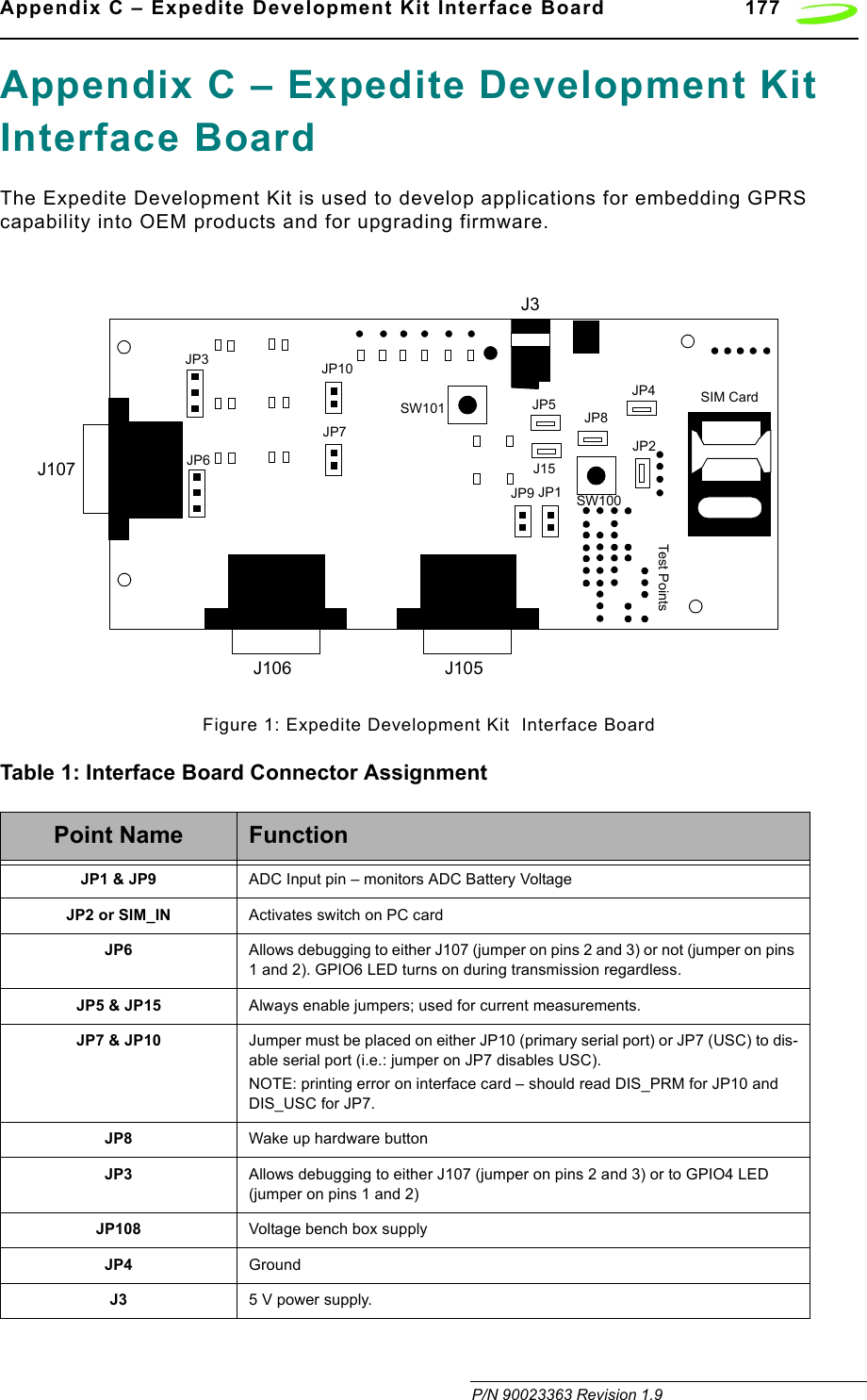
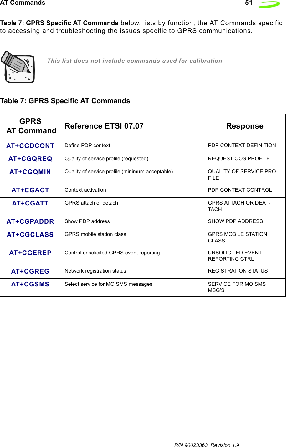
Novatel Wireless NRM-EG301 PCS OEM Module User Manual GPRS Technical Specifications
Novatel Wireless, Inc. PCS OEM Module GPRS Technical Specifications
Contents
- 1. Quick Start Guide
- 2. Users Manual Part I
- 3. Users Manual Part II
- 4. Revised Users manual
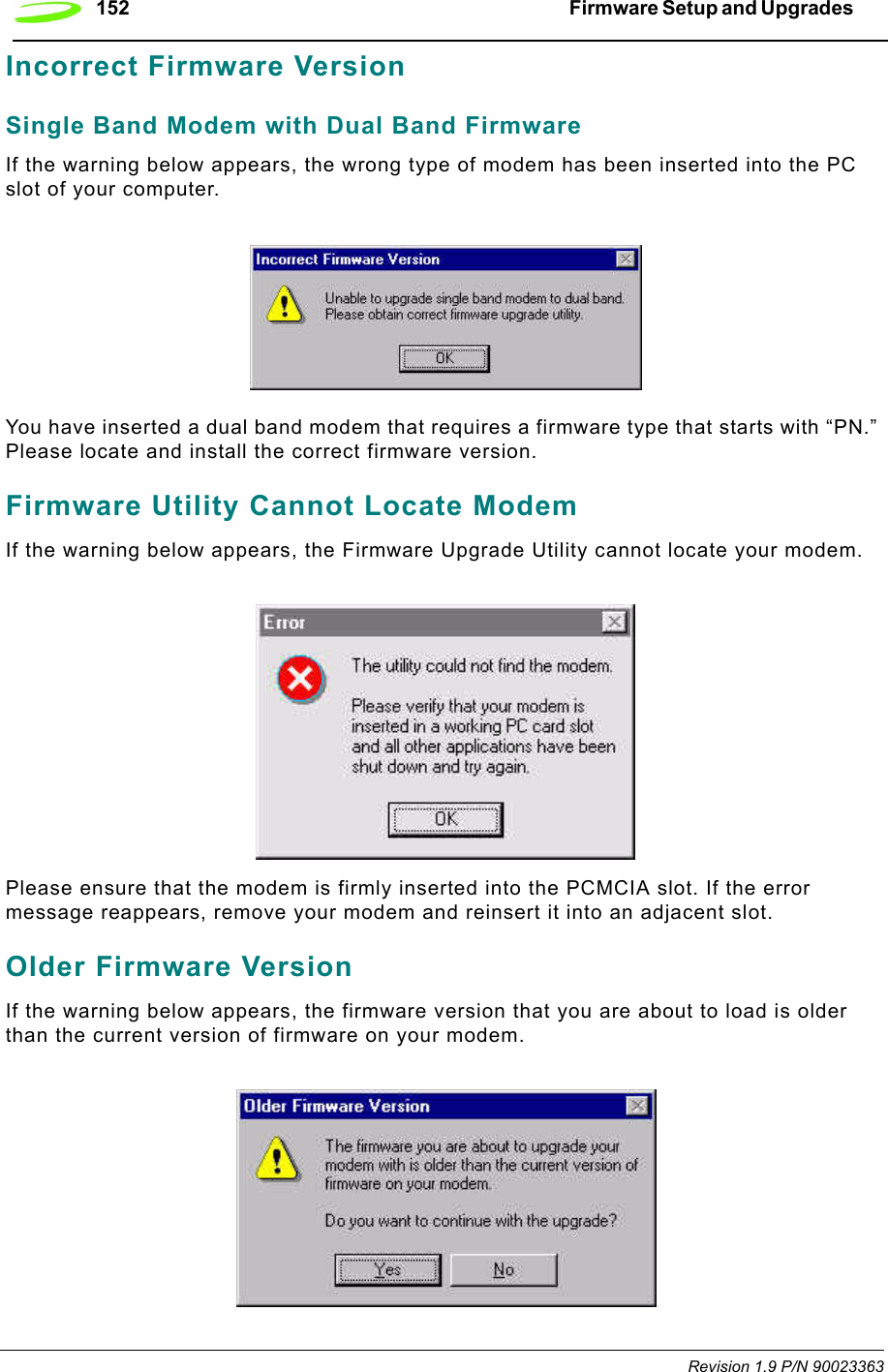
Revised Users manual
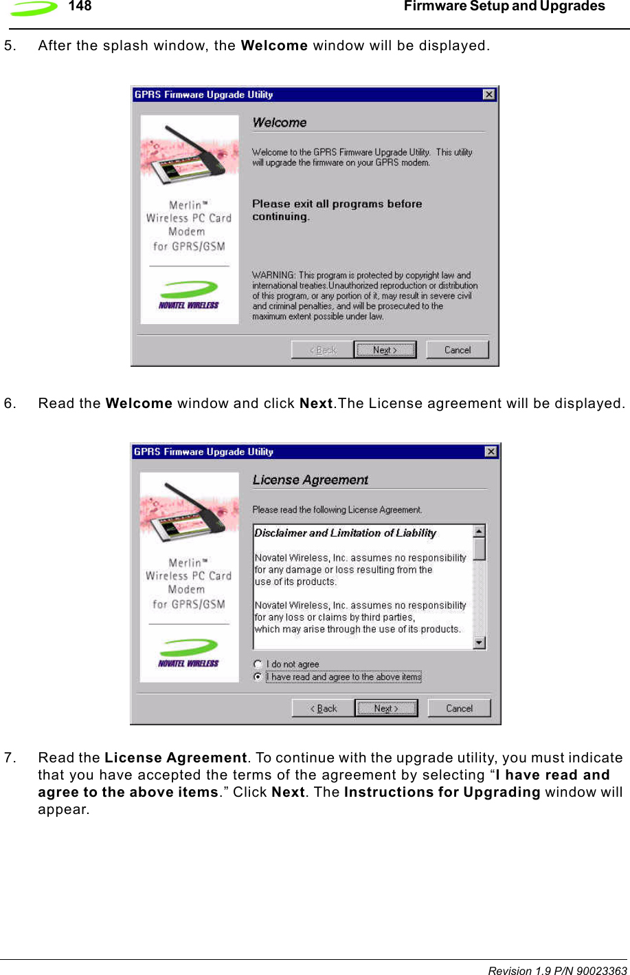
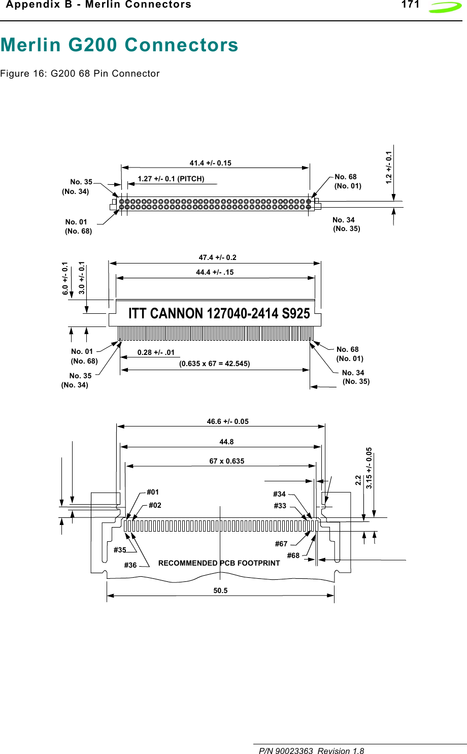
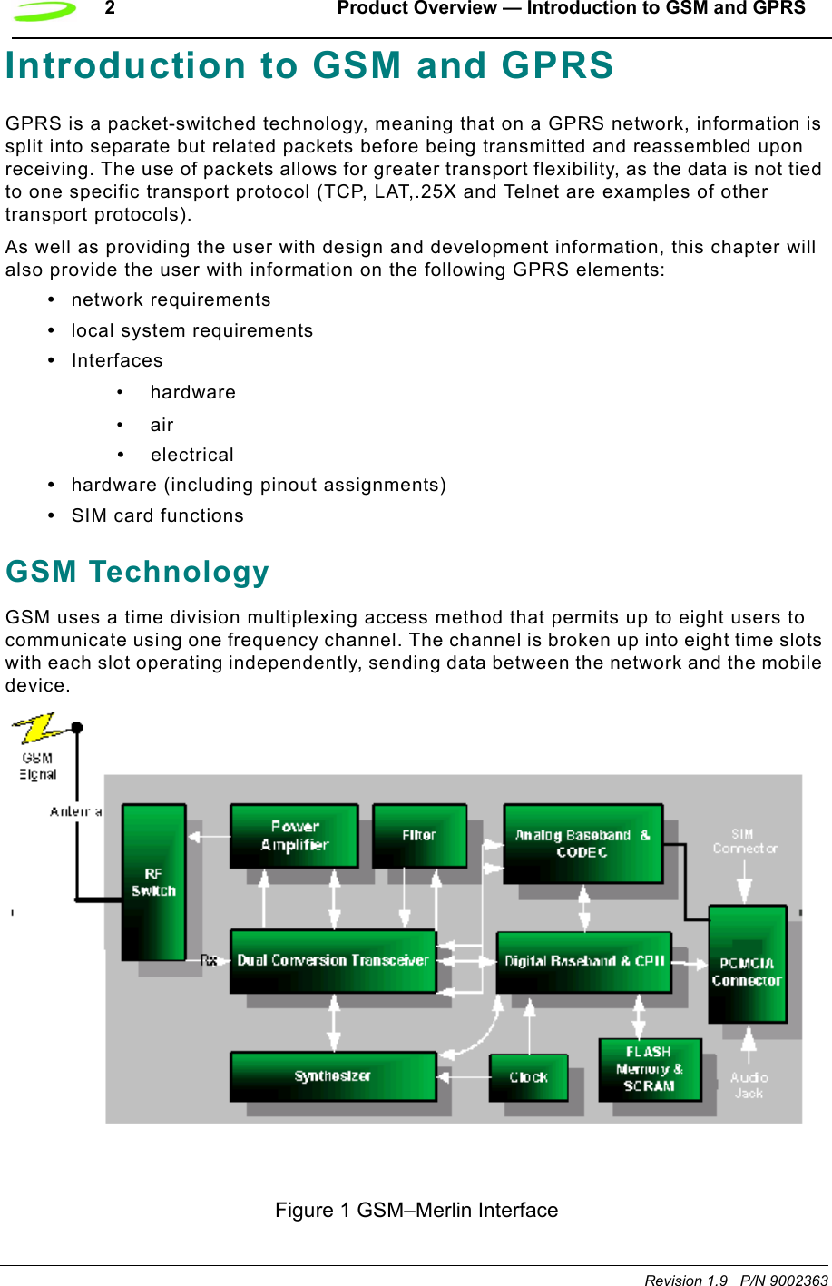
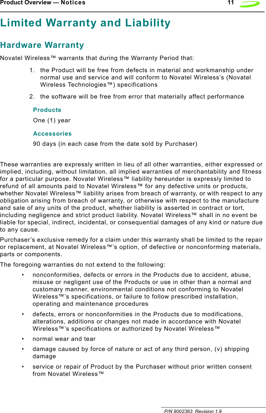
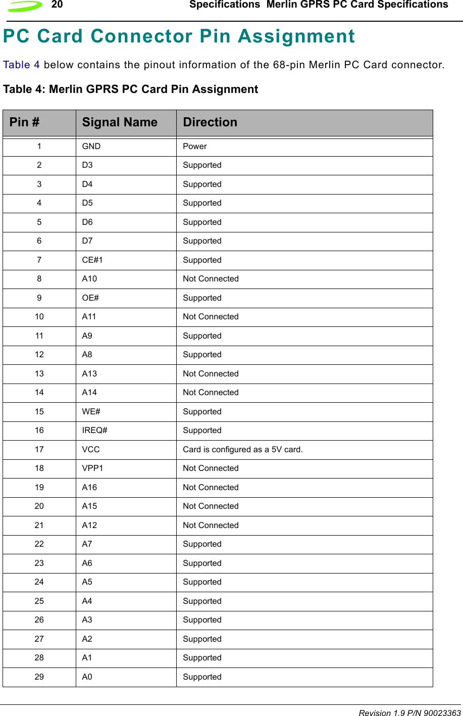
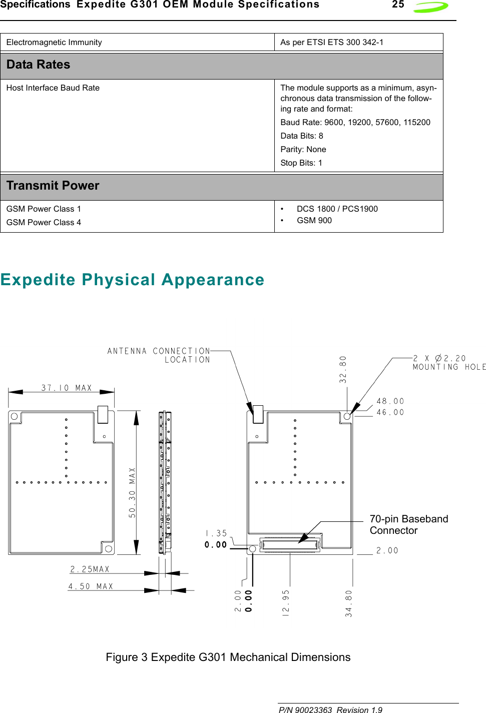
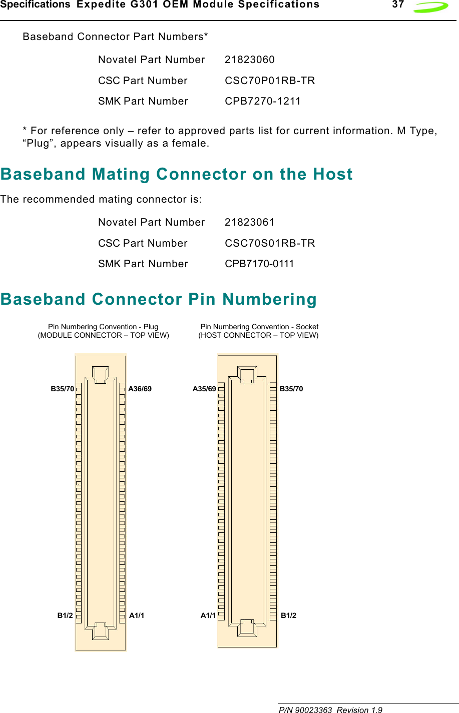
![iiRevision 1.9 P/N 90023363 Mounting Features.........................................................................................................................38Air Interface .................................................................................................................. 38Subscriber Identification Module (SIM)...................................................................... 39Modes of Operation ..................................................................................................... 40Sleep..............................................................................................................................................40SMS Messaging.............................................................................................................................40Circuit Switched .............................................................................................................................40GPRS Data ....................................................................................................................................40Standby..........................................................................................................................................41Application Information............................................................................................... 41Chapter 3: AT CommandsAT Command Set by Function .............................................................................................................44AT Command Set by Name .................................................................................................................53A/..........................................................................................................................................................53+++ .......................................................................................................................................................53ATA ......................................................................................................................................................54ATD[<n>][mgsm>] ................................................................................................................................54ATD[<mem><loc>][<mgsm>] ...............................................................................................................56ATD[<ploc>][<mgsm>] .........................................................................................................................57ATD[<str>][<mgsm>] ............................................................................................................................59ATDL ....................................................................................................................................................61ATE ......................................................................................................................................................62ATH ......................................................................................................................................................62ATI........................................................................................................................................................63ATI0......................................................................................................................................................63ATL.......................................................................................................................................................63ATM......................................................................................................................................................64ATO......................................................................................................................................................64ATP ......................................................................................................................................................65ATQ......................................................................................................................................................65ATS0 ....................................................................................................................................................66ATS2 ....................................................................................................................................................66ATS3 ....................................................................................................................................................67ATS4 ....................................................................................................................................................67ATS5 ....................................................................................................................................................68ATS6 ....................................................................................................................................................69ATS7 ....................................................................................................................................................69ATS8 ....................................................................................................................................................70ATS10 ..................................................................................................................................................70ATS12 ..................................................................................................................................................71ATT ......................................................................................................................................................71ATV ......................................................................................................................................................72ATX ......................................................................................................................................................72ATZ ......................................................................................................................................................73AT&C....................................................................................................................................................74AT&D....................................................................................................................................................74AT&F ....................................................................................................................................................74AT&V ....................................................................................................................................................75AT&W ...................................................................................................................................................76](https://usermanual.wiki/Novatel-Wireless/NRM-EG301.Revised-Users-manual/User-Guide-315684-Page-4.png)
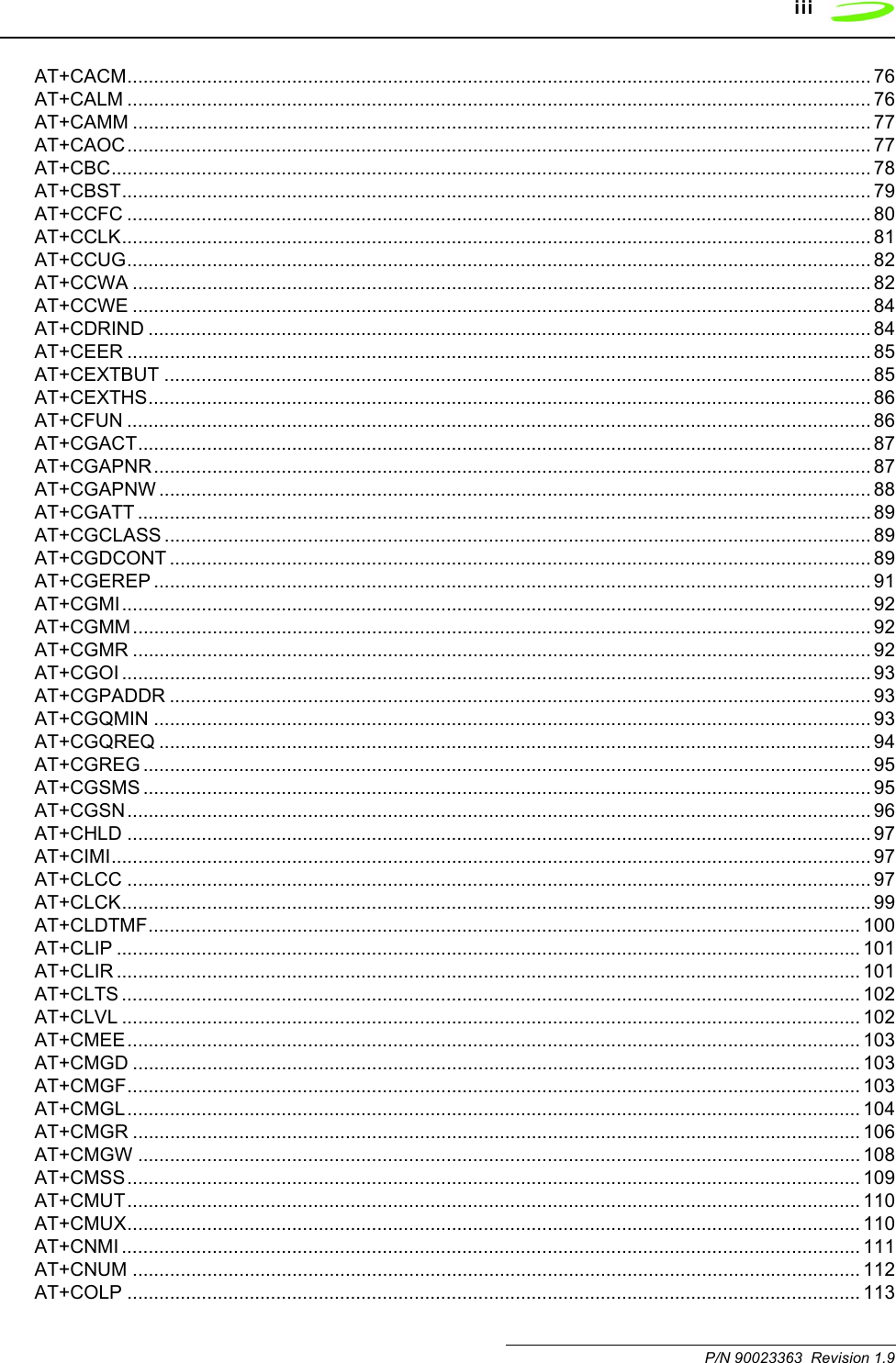


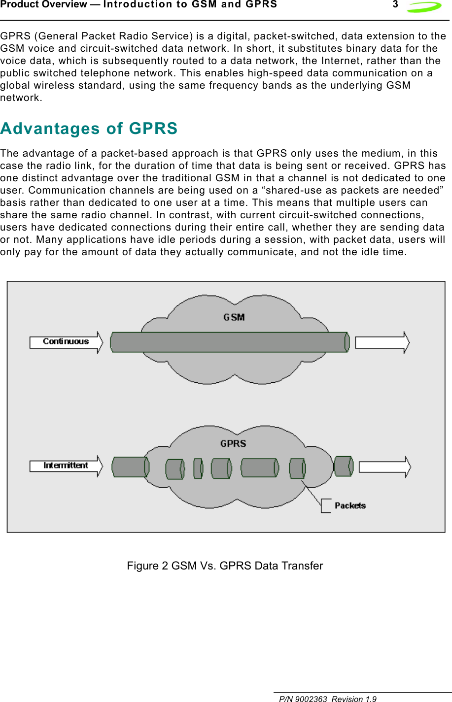
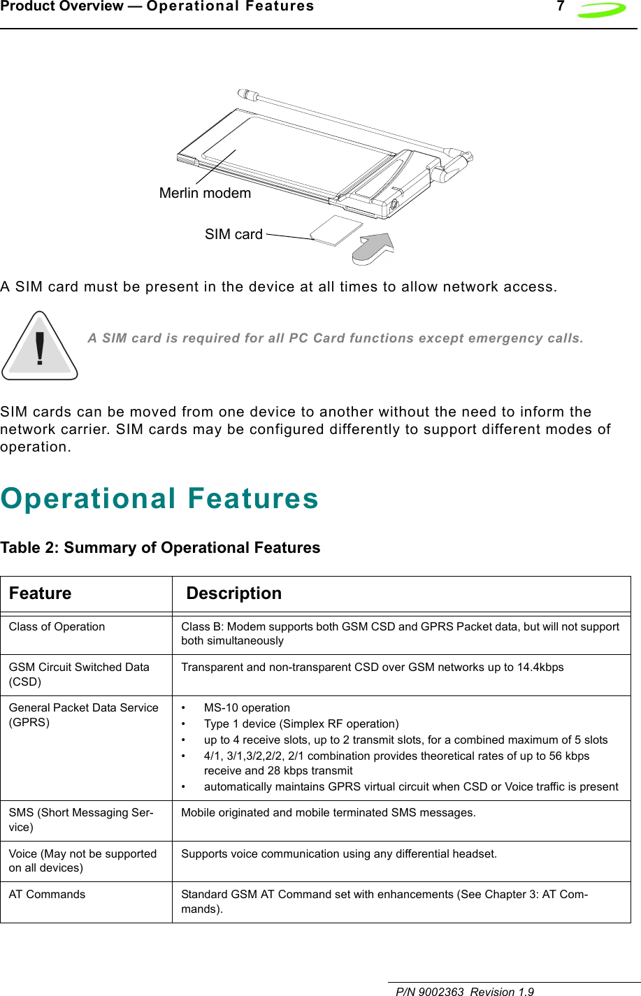
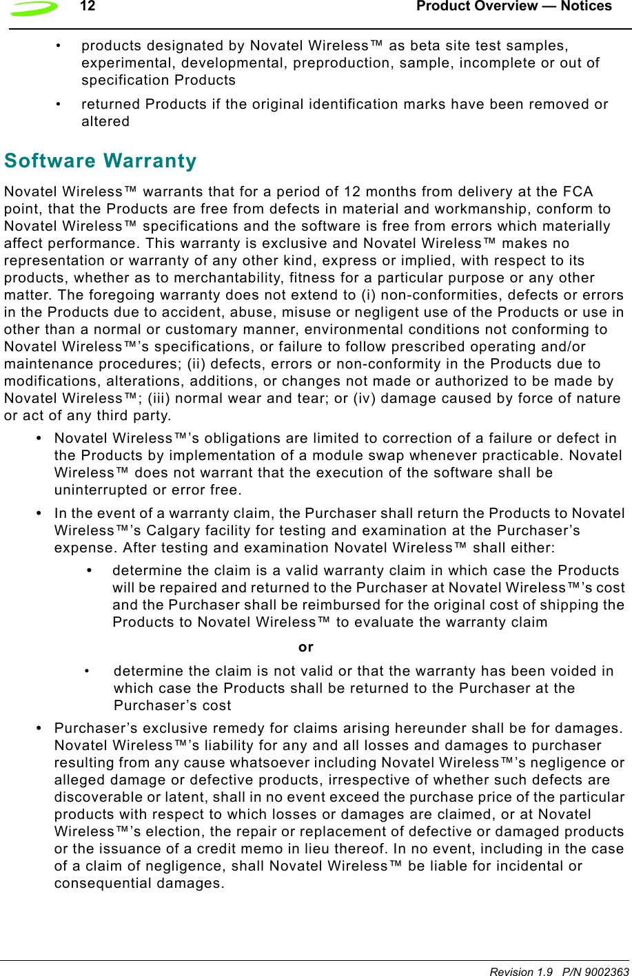


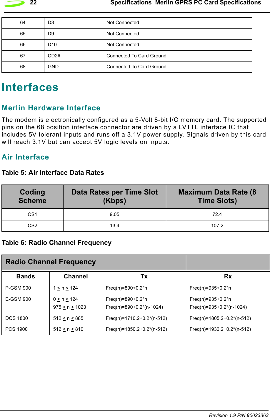
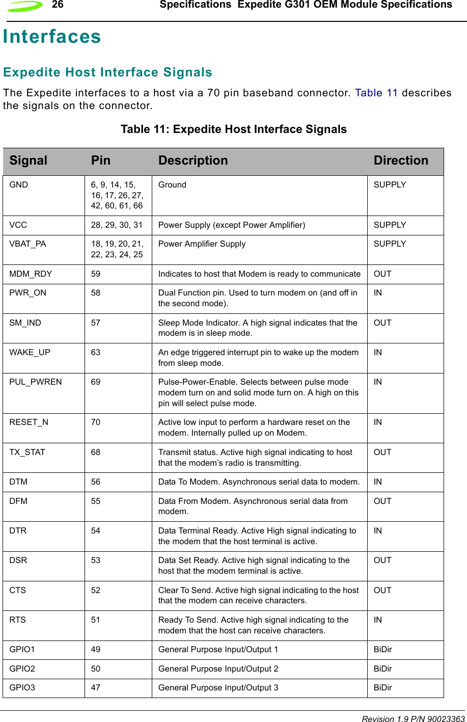
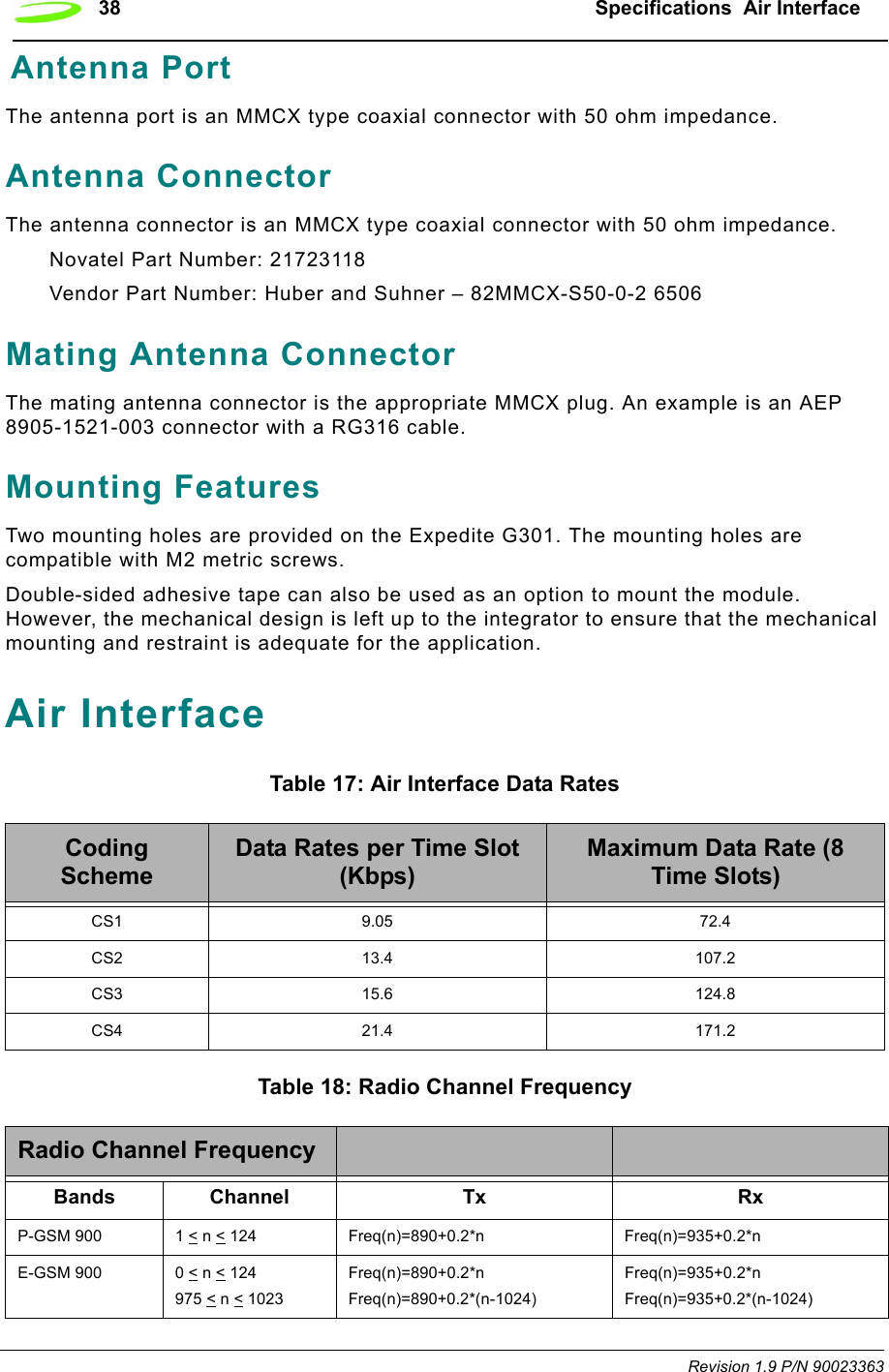

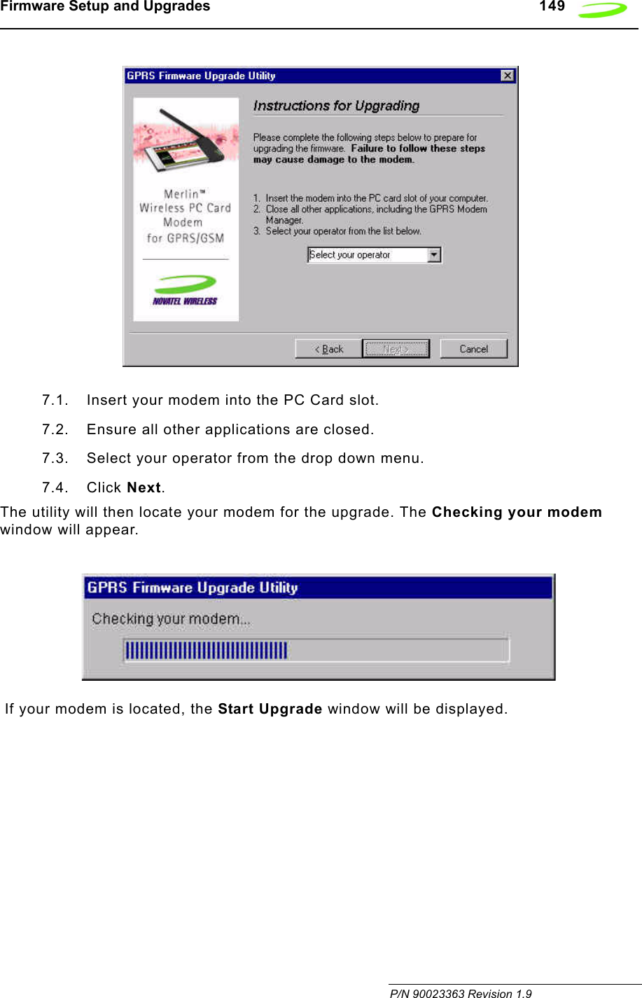
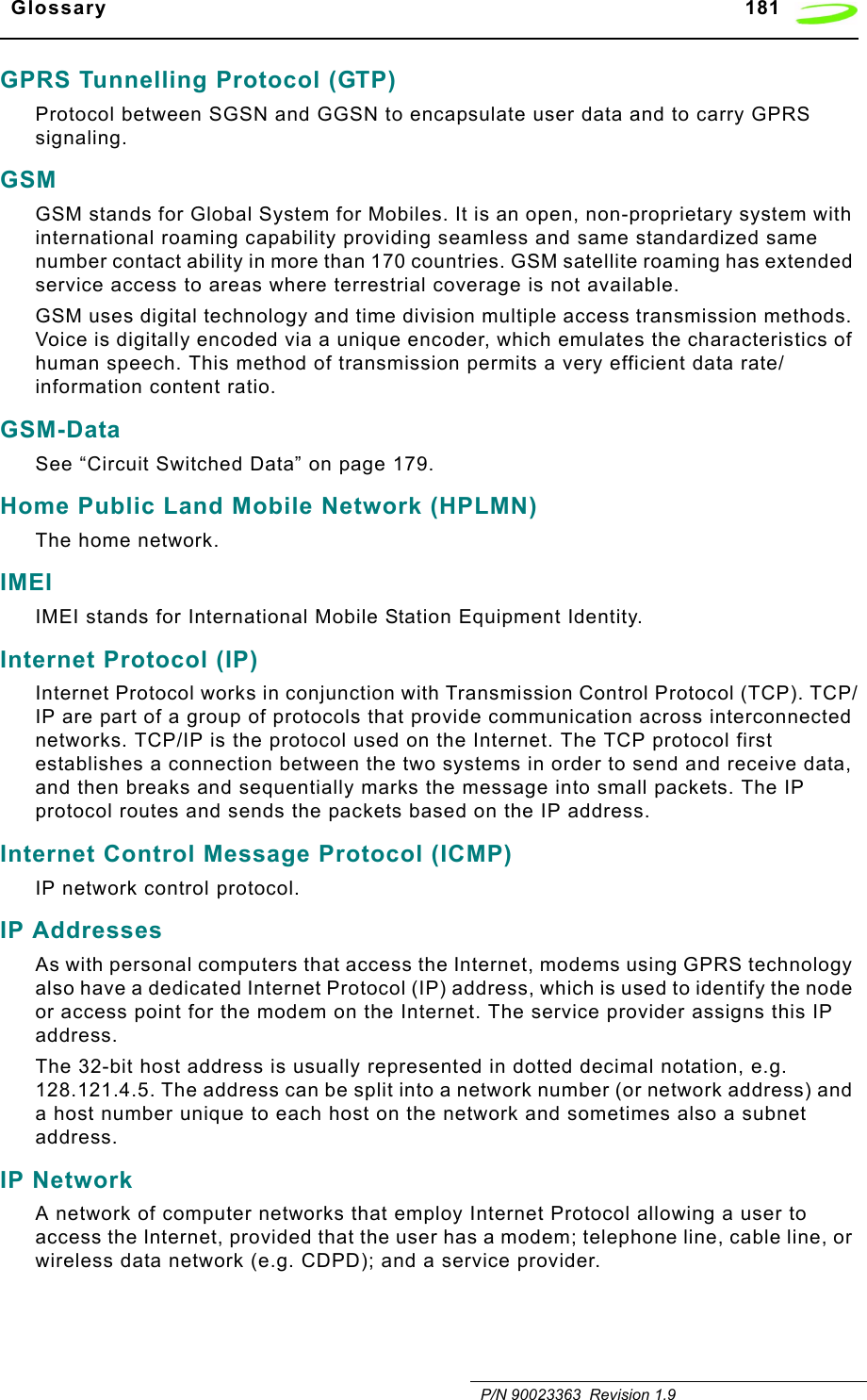
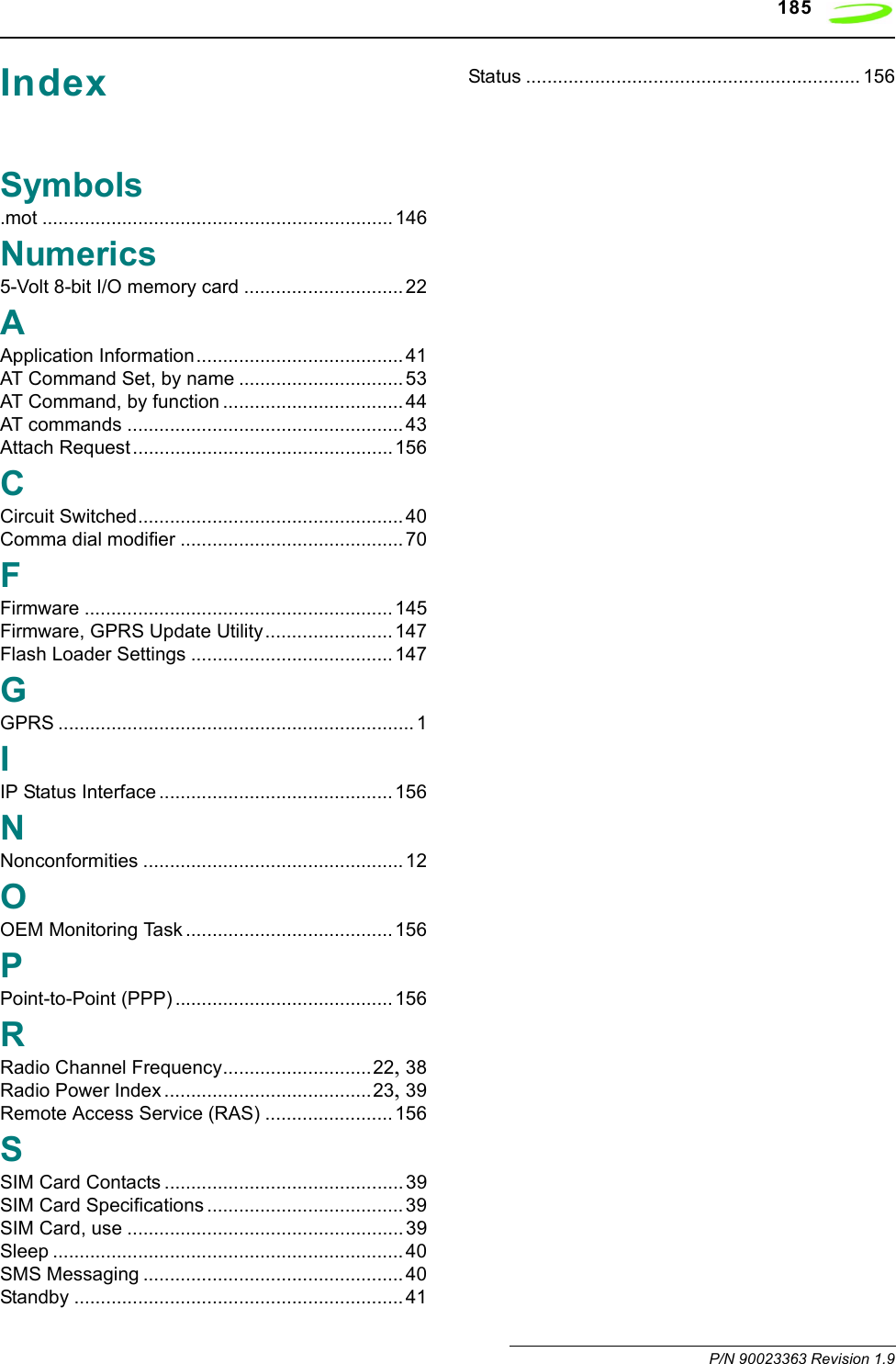
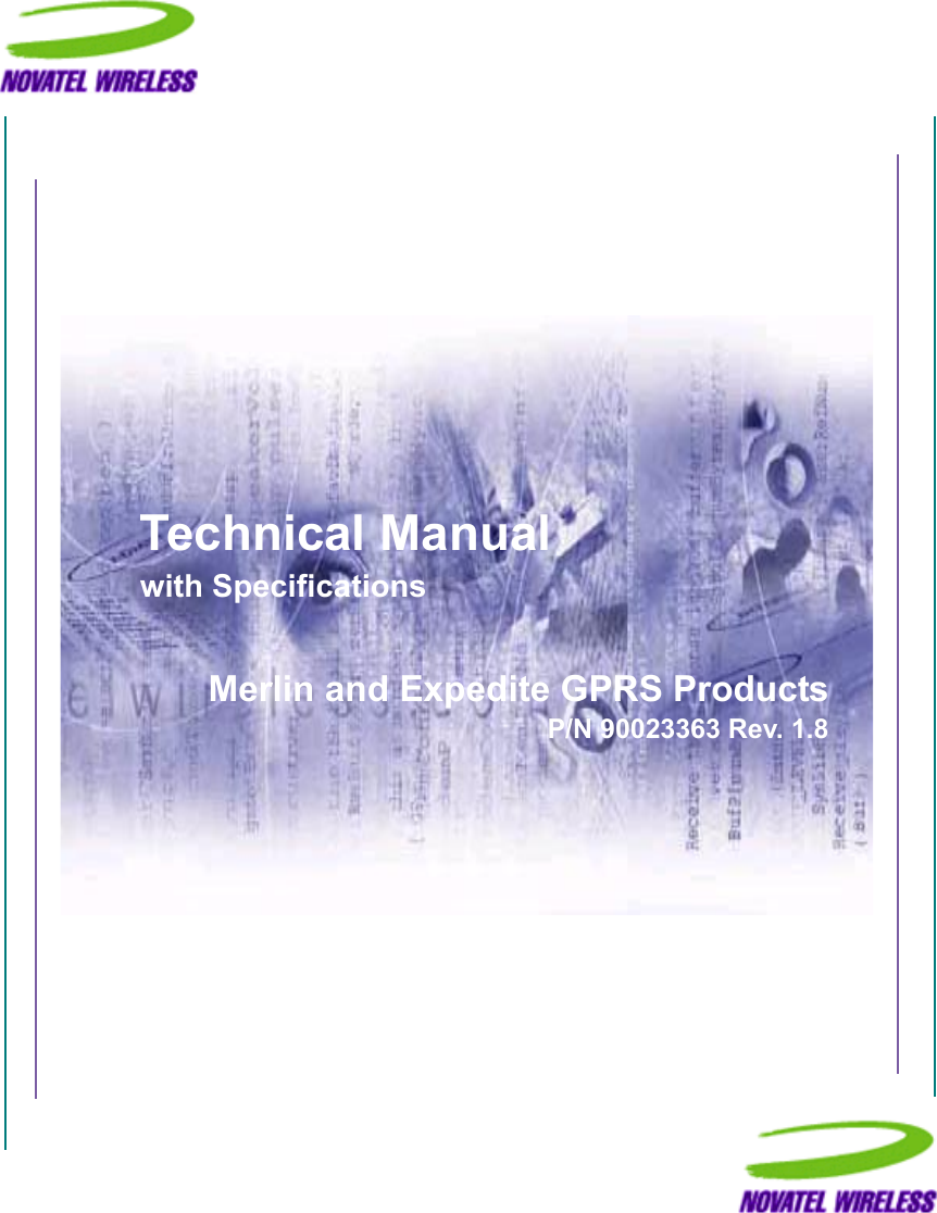
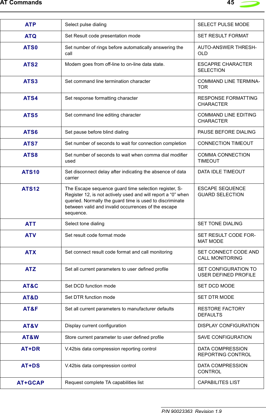
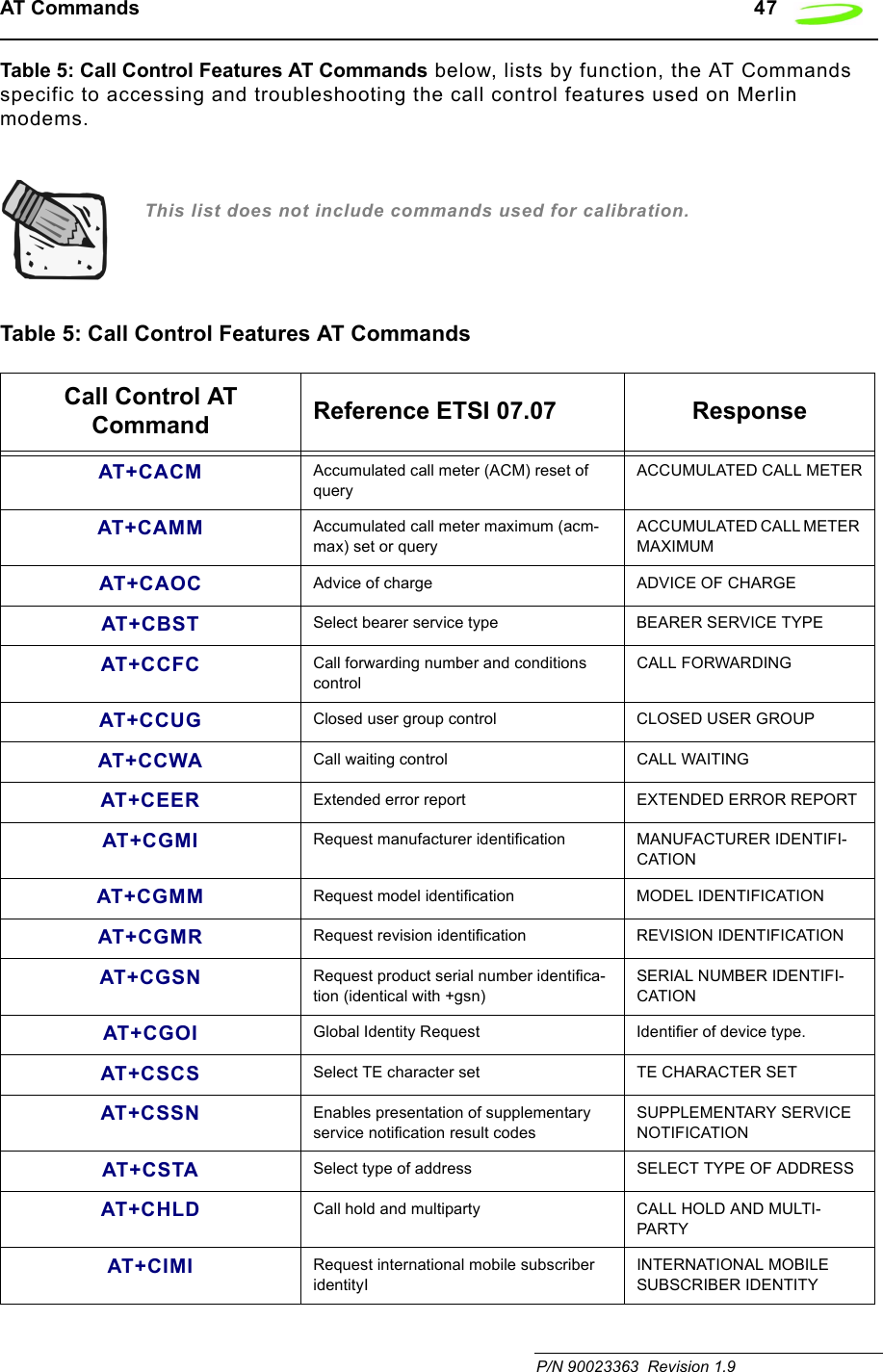
![44 AT Commands Revision 1.9 P/N 90023363AT Command Set by FunctionTable 4: Generic AT Commands below, lists by function, the generic AT Commands that can be used with Merlin modems. The general format of the command line is: <prefix><command><cr>. This list does not include commands used for calibration.Simply move the mouse over the command to link to a detailed explanation.Table 4: Generic AT CommandsGeneric AT Command Reference ETSI 07.07,PCCA STD-101 ResponseA/ Re-issues last AT command given AGAIN+++ ESC from Data mode to command mode ESCAPEATA Answer incoming call ANSWERATD[<n>][mgsm>] Mobile Originated call to dial table number DIALATD[<mem><loc>][<mgsm>]Originate call to phone number in memory <MEM>DIAL FROM MEM-ORYATD[<ploc>][<mgsm>]Originate call to phone number in current memory DIAL FROM LOCATIONATD[<str>][<mgsm>]Originate call to phone number in memory which corre-sponds to alphanumeric field <STR>DIAL USING STRINGATDL Redial last telephone number used DIAL LAST NUMBERATE Set command echo mode ECHO MODEATH Disconnect existing connection HANG-UP (DISCONNECT)ATI Display product identification information DISPLAY IDENTITYATI0 Request IMEI (International Mobile Equipment Identifier) number.IMEI: 001018-00-565563-5-00 IMEI OKATL Set monitor speaker loudness SET SPEAKER LOUDNESSATM Set monitor speaker mode SET SPEAKER MODEATO Switch from command mode to data mode OPEN DATA MODE](https://usermanual.wiki/Novatel-Wireless/NRM-EG301.Revised-Users-manual/User-Guide-315684-Page-52.png)
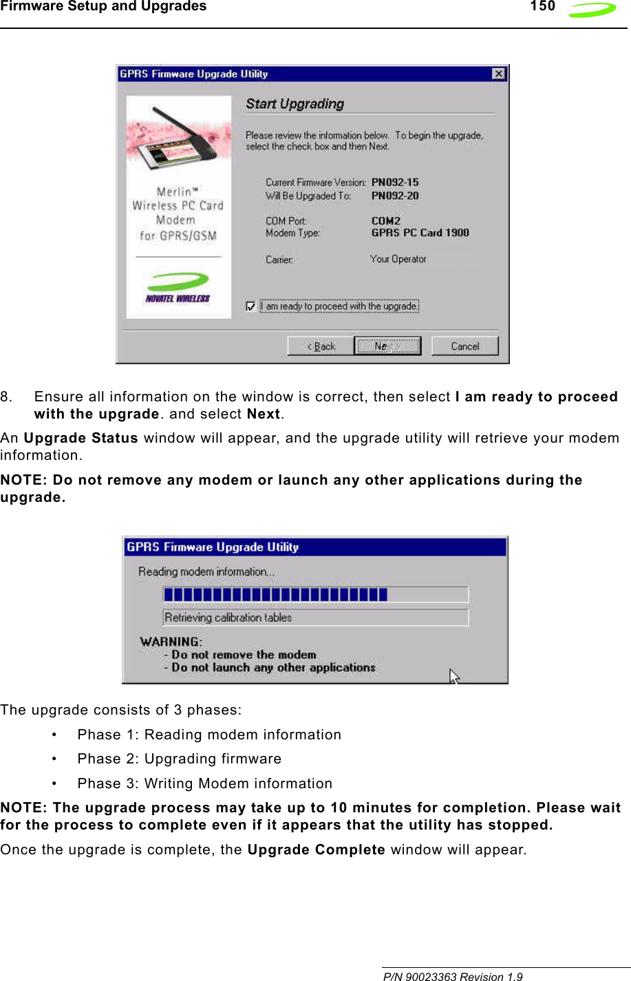
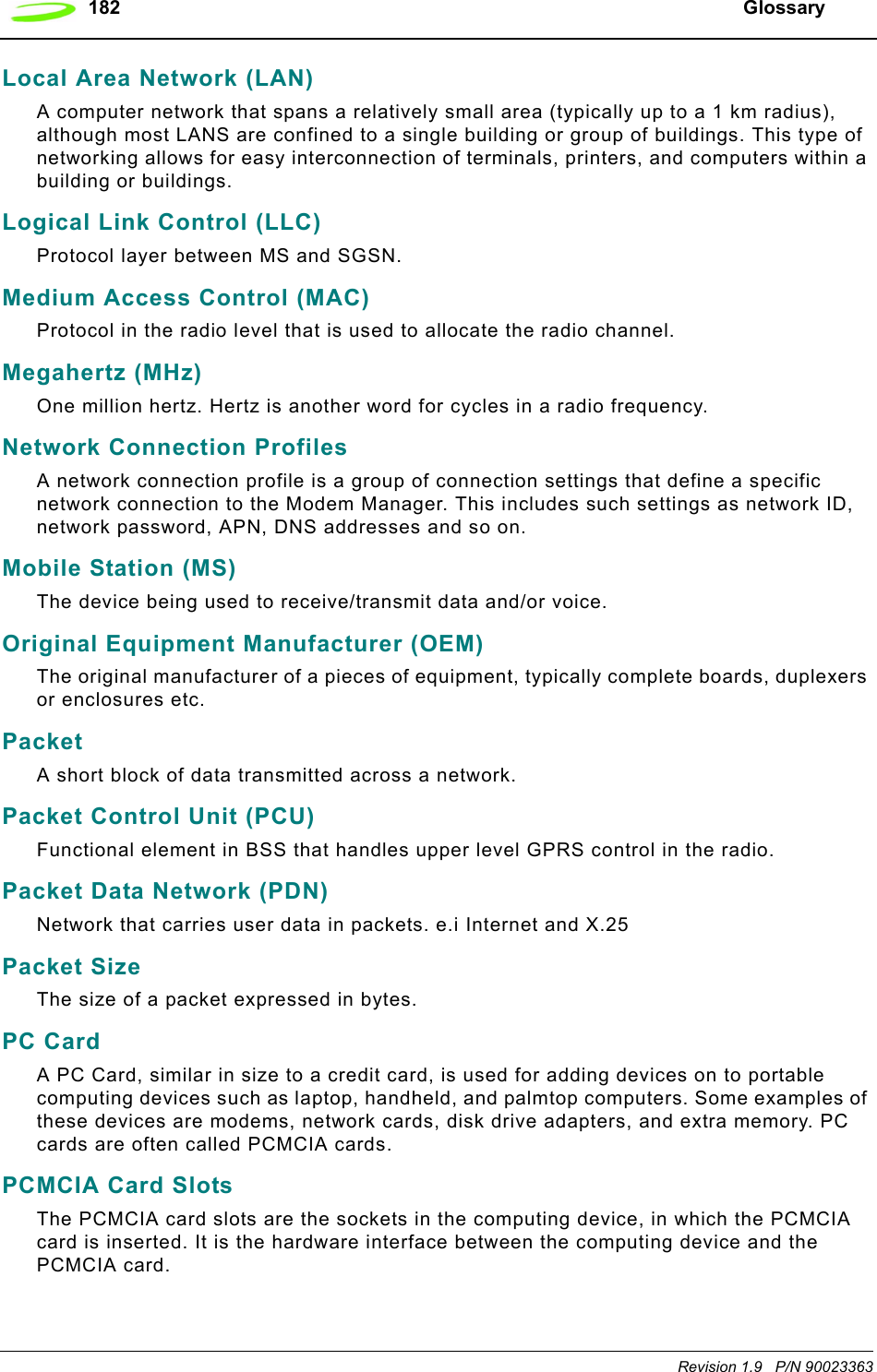
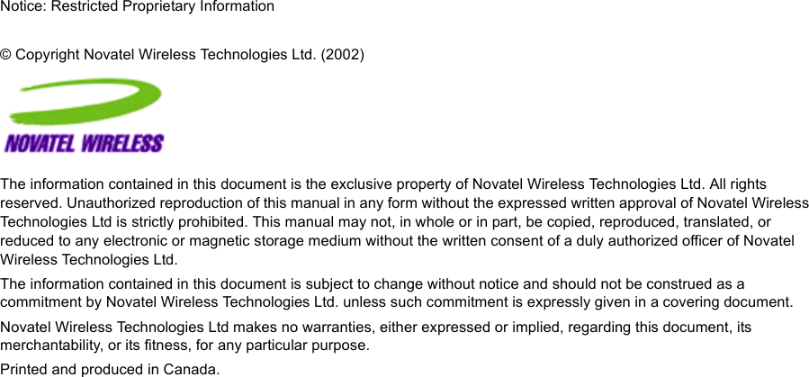
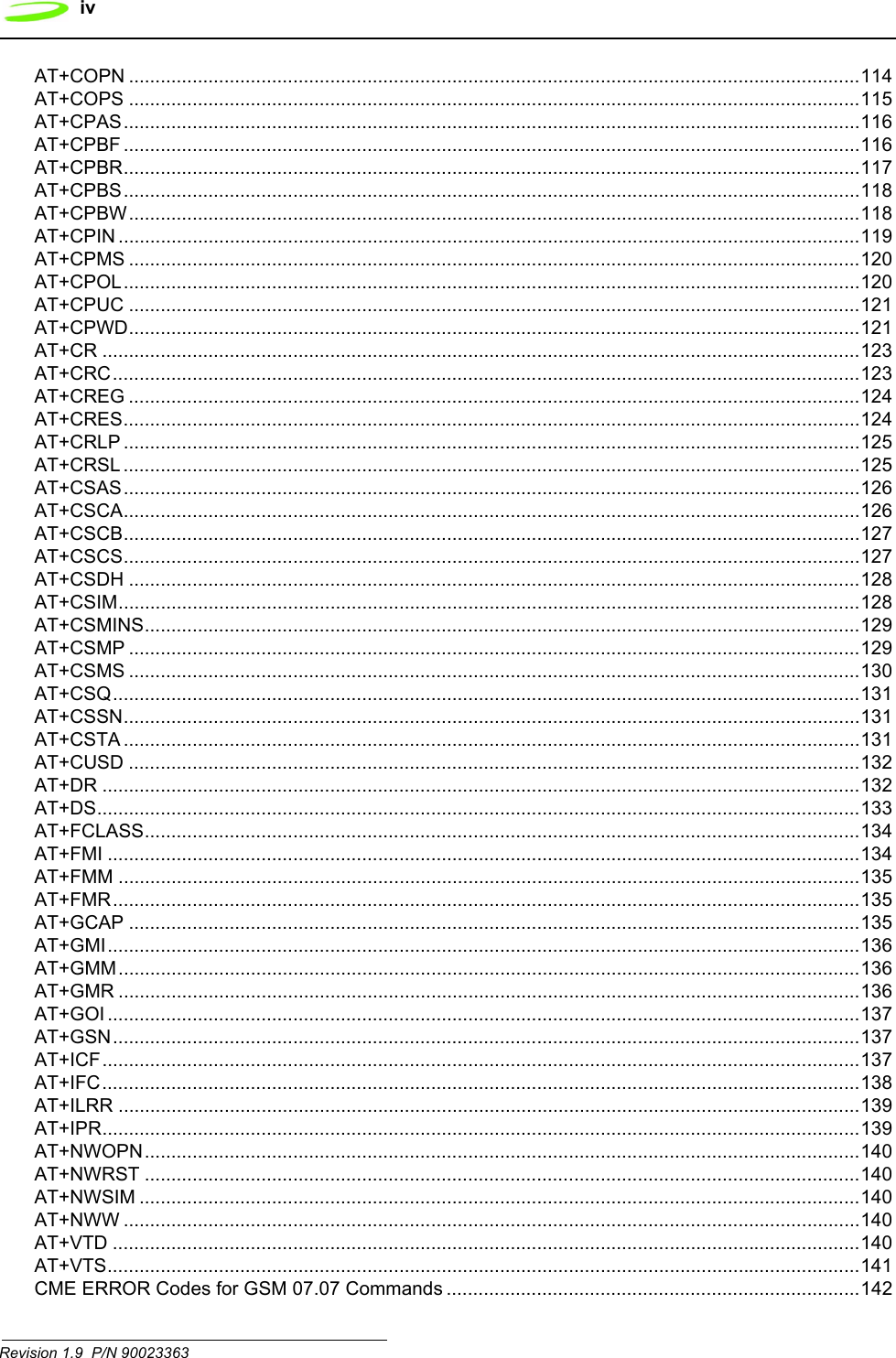
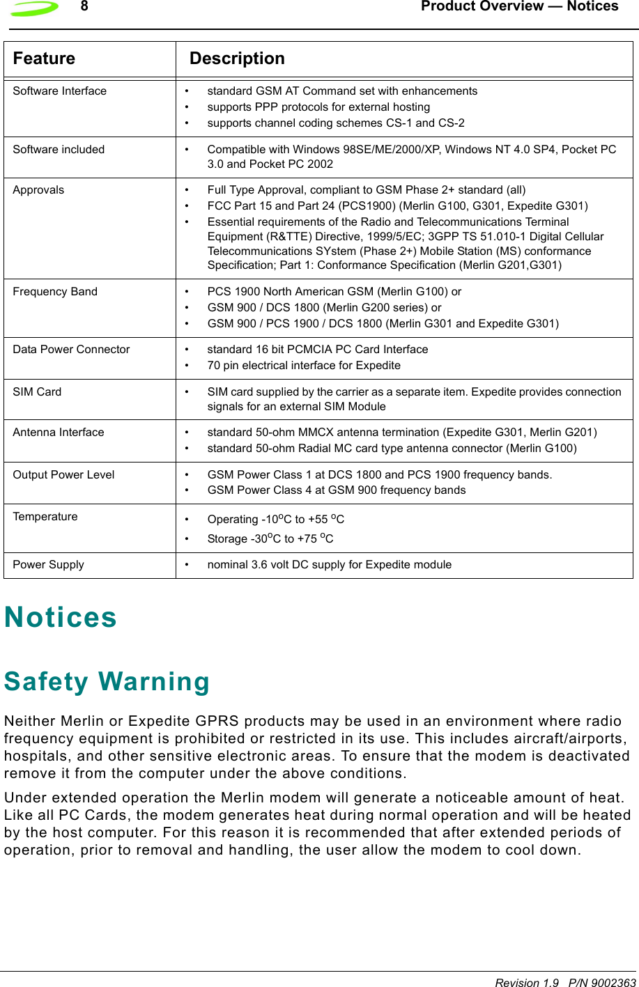
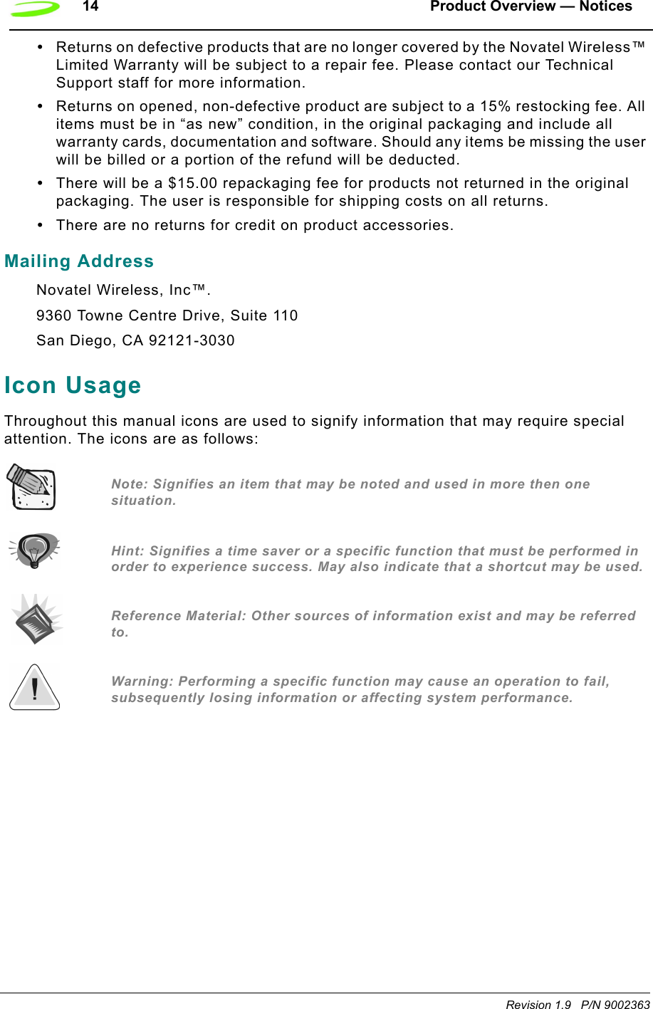
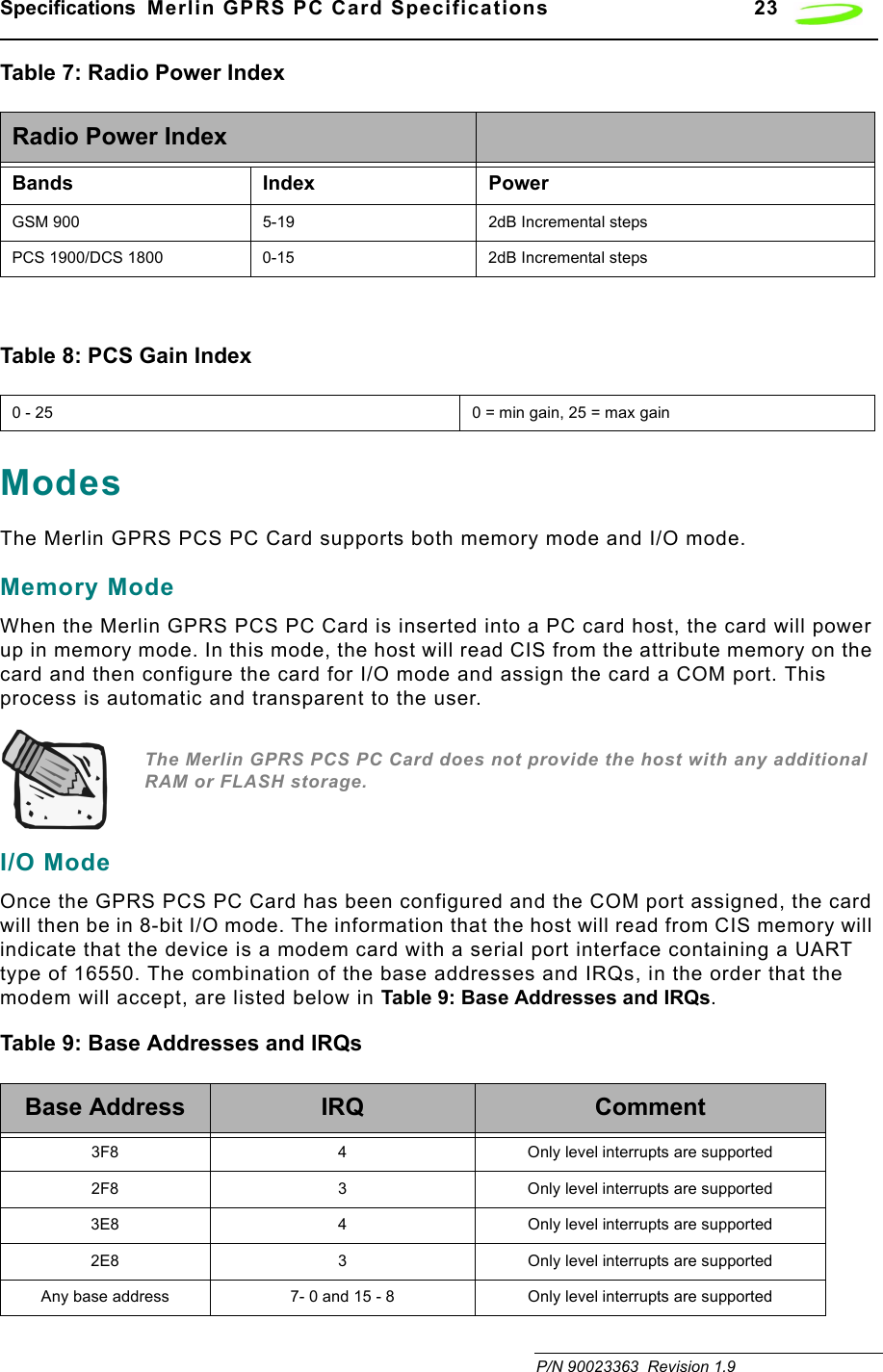
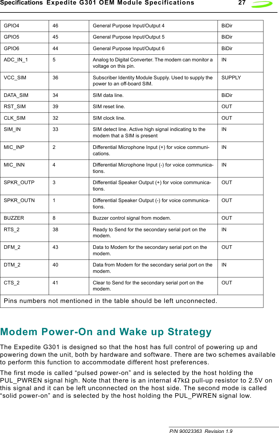
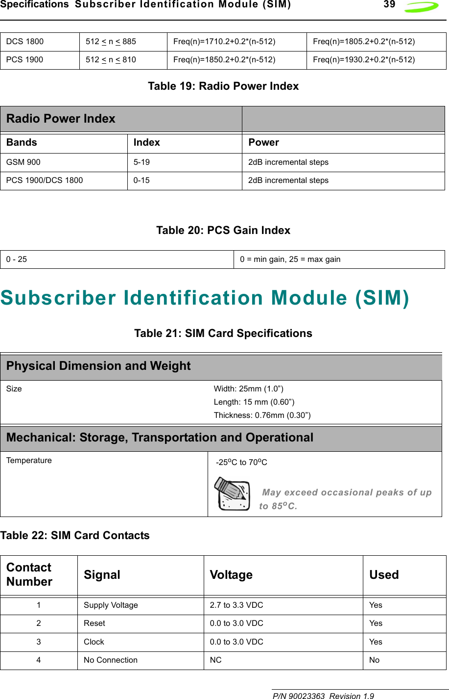
![54 AT Commands Revision 1.9 P/N 90023363This command is not a Hayes-compatible command. It is a public domain method (TIES) and is only enabled with define VG_TIES_ESC_SEQUENCE.Syntax: +++<cr>Parameters: NoneResponse: This command will return the string OK.Example: +++AT <cr>ATADescription: ANSWER This command sets the modem to answer the next call. The modem sends an off-hook signal to the remote station. Any additional commands on the same command line are ignored. The modem switches to data mode and after call is released, returns to command mode.This command can be stopped by receiving a character during execution, except during some states of connection establishment such as handshaking.Syntax: ATA<cr>Parameters: NoneResponse: If the connection is successful the modem will return the string:CONNECT<text>then switches to data mode. The <text> is only displayed if the command ATX has been set to a value greater than 0.When the modem releases the call and returns to command mode, it returns the string:OKIf no connection is made, the modem will return the string:NO CARRIERExample: ATA<cr>ATD[<n>][mgsm>]Description: DIAL NUMBERThis command will instruct the modem to originate a call to a dialable number. The modem attempts to set up an outgoing call.This command can be stopped by receiving a character during execution, except during some states of connection establishment such as handshaking.](https://usermanual.wiki/Novatel-Wireless/NRM-EG301.Revised-Users-manual/User-Guide-315684-Page-62.png)
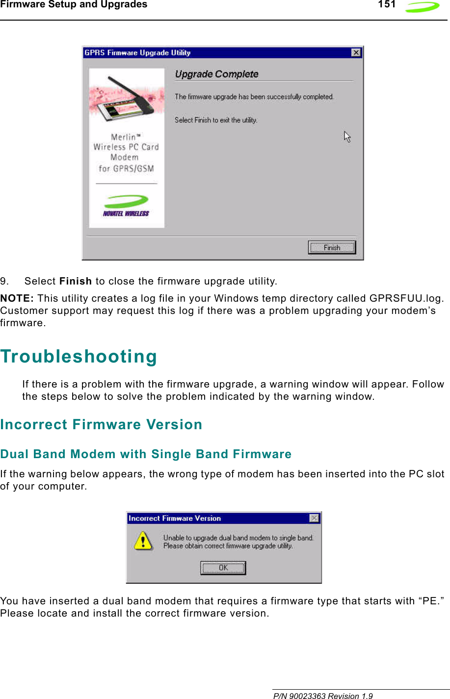
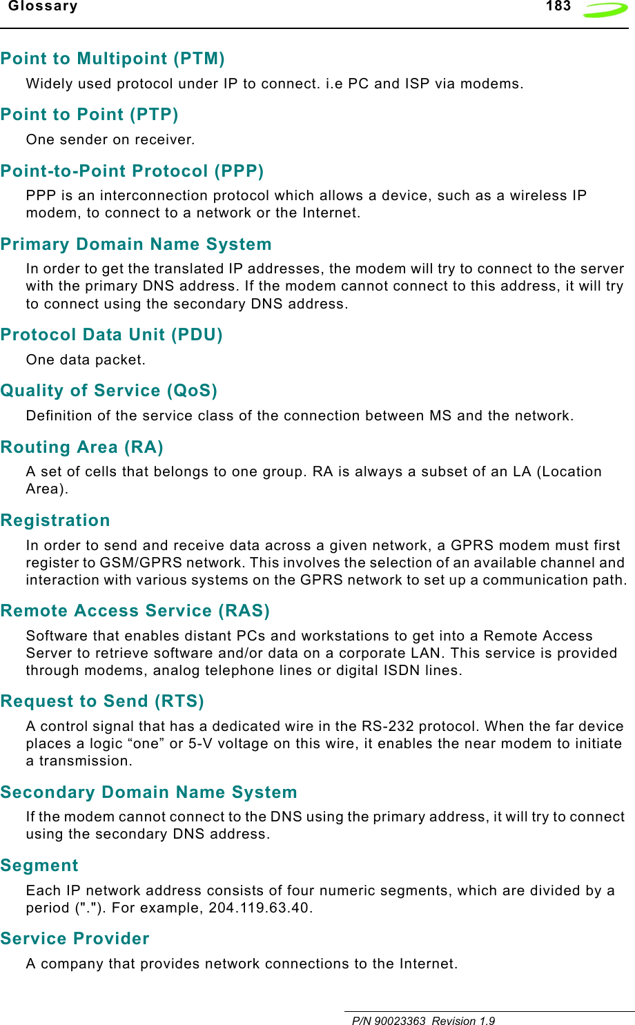
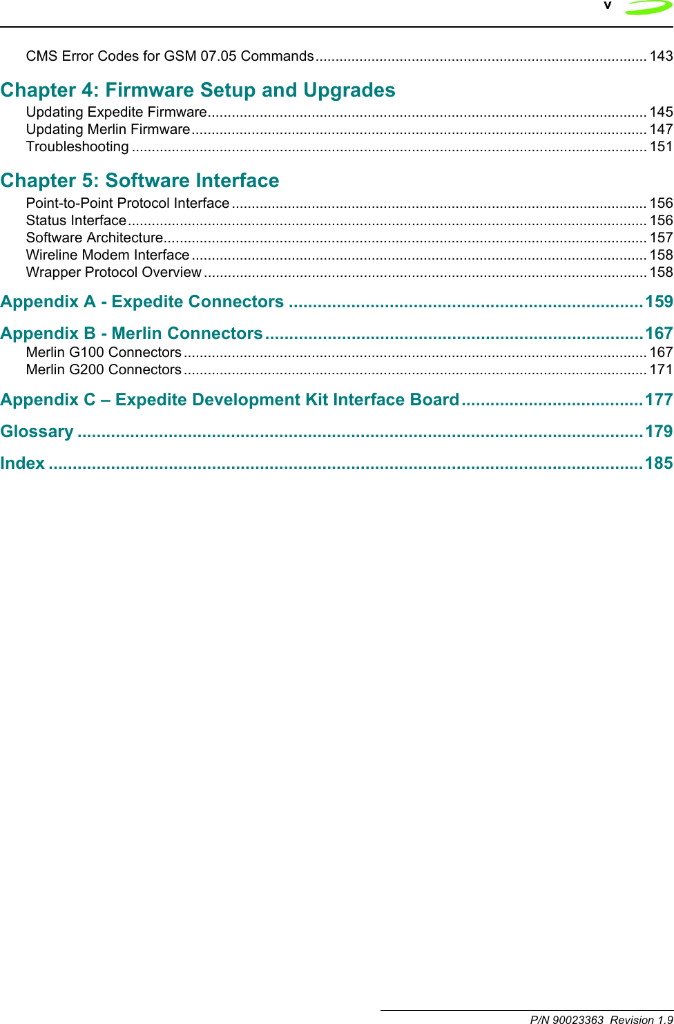
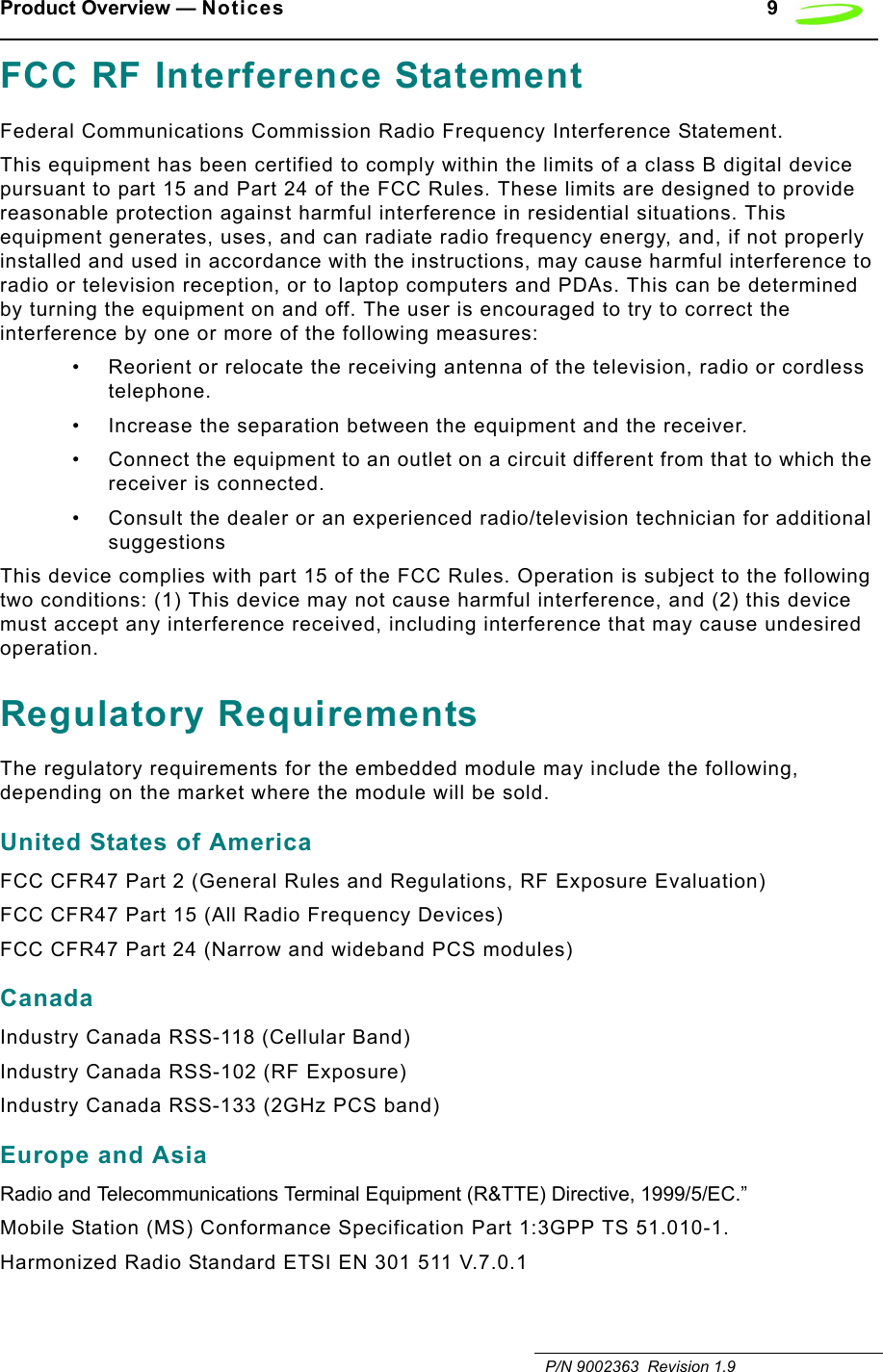
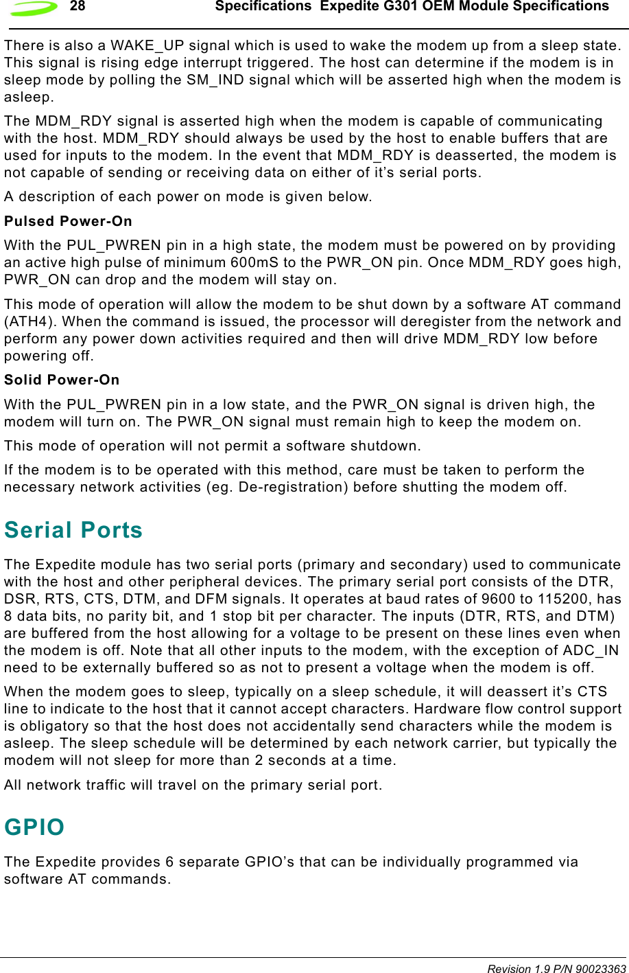
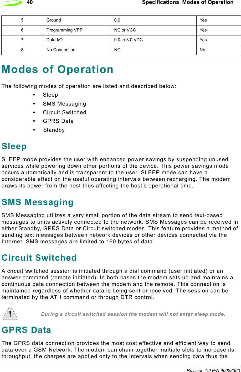
![AT Commands 55 P/N 90023363 Revision 1.9Syntax: ATD[<n>][<mgsm>]<cr>Parameters:n is the string of dialing digits and the optional V.25ter modifiers. The valid dialing digits are:0-9, * , #, +, A, B, Cand the V.25ter modifiers which are ignored:mgsm is a string of GSM modifiers, where:I is overrides the current Calling Line Identification Restriction (CLIR) setting for the callG,g displays the Closed User Group (CUG) information, set with the command +CCUG;signifies the call is a voice call and instructs the modem to return to the command mode.Response: If there is no dial tone, the modem will return the string:NO DIALTONEwhere the command ATX has been set to 2 or 4.If there is an error and it is related to the mobile equipment’s (ME) functionality, the modem will return the string:+CME ERROR: <error>If the connection is busy, the modem will return the string:BUSYwhere the command ATX has been set to 3 or 4.If the connection cannot be established, the modem will return the string:NO CARRIERIf the connection is successful and is non-voice call, the modem switches to data state and the modem will return the string:CONNECT<text>where <text> is only displayed if the command ATX has been set to a value greater than 0.If connection successful and is a voice call, the modem will return the string:OKWhen the modem releases the call and returns to command mode, it returns the string:OK](https://usermanual.wiki/Novatel-Wireless/NRM-EG301.Revised-Users-manual/User-Guide-315684-Page-63.png)
![56 AT Commands Revision 1.9 P/N 90023363Example:ATD9,555-1212<cr> DIAL 9, PAUSE, DIAL 5551212ATD555-1234;<cr> DIAL 5551234ATD555-09871G<cr> DIAL 5550987, OVERRIDE CLIR, DISPLAY CUGATD[<mem><loc>][<mgsm>]Description: DIAL NUMBER FROM SIM PHONE BOOK MEMORYThis command will instruct the modem to originate a call to a dialable number using reference to a number stored in the SIM’s phone book memories.Syntax: ATD[<mem><loc>][<mgsm>]Parameters:mem is the phone book at the designated memory location. There is no <mem> for emergency calls (EN). It is comprised of the following phone book parameters:FD SIM fix phone-phone bookLD SIM last-phone-phone bookDC Mobile Equipment (ME) dialed calls listON SIM (or ME) own numbers (MSISDNs) listSM SIM phone bookloc is an integer referring to a memory location that is in a range of locations available in the phone book referenced. This must be used with the mem parameter.mgsm is a string of GSM modifiers, where:I is overrides the current Calling Line Identification Restriction (CLIR) setting for the callG,g displays the Closed User Group (CUG) information, set with the command +CCUG;signifies the call is a voice call and instructs the modem to return to the command mode.Response: If there is no dial tone, the modem will return the string:NO DIALTONEwhere the command ATX has been set to 2 or 4.If there is an error and it is related to the mobile equipment’s (ME) functionality, the modem will return the string:+CME ERROR: <error>](https://usermanual.wiki/Novatel-Wireless/NRM-EG301.Revised-Users-manual/User-Guide-315684-Page-64.png)
![AT Commands 57 P/N 90023363 Revision 1.9If the connection is busy, the modem will return the string:BUSYwhere the command ATX has been set to 3 or 4.If the connection cannot be established, the modem will return the string:NO CARRIERIf the connection is successful and is non-voice call, the modem switches to data state and the modem will return the string:CONNECT<text>where <text> is only displayed if the command ATX has been set to a value greater than 0.If connection successful and is a voice call, the modem will return the string:OKWhen the modem releases the call and returns to command mode, it returns the string:OKExample: ATDFD1<cr> DATA CALL TO FD PHONE BOOK ENTRY ATDLD3<cr> DATA CALL TO LD PHONE BOOK ENTRY ATDDC2I;<cr> VOICE CALL TO DC PHONE BOOK ENTRY 2 NO CLIRATD[<ploc>][<mgsm>]Description: DIAL NUMBER FROM INTERNAL MEMORYThis command will instruct the modem to originate a call to a dialable numberSyntax: ATD[<ploc>][<mgsm>]<cr>Parameters:ploc is an integer referring to a mobile equipment phone number stored at the specified location in the modem’s internal memory.mgsm is a string of GSM modifiers, where:I overrides the current Calling Line Identification Restriction (CLIR) setting for the callG,g displays the Closed User Group (CUG) information, set with the command +CCUG;signifies the call is a voice call and instructs the modem to return to the command mode.](https://usermanual.wiki/Novatel-Wireless/NRM-EG301.Revised-Users-manual/User-Guide-315684-Page-65.png)
![AT Commands 59 P/N 90023363 Revision 1.9ATD[<str>][<mgsm>]Description: DIAL NUMBR FROM NAME SEARCHThis command will instruct the modem to originate a call to a dialable number. Syntax: ATD[<str>][<mgsm>]<cr>Parameters:str is a string that is searched for in the alphanumeric fields of the phone books, located in all available memory types (i.e. SIM, Mobile Equipment Phone Book, etc.).mgsm is a string of GSM modifiers, where:I is overrides the current Calling Line Identification Restriction (CLIR) setting for the callG,g displays the Closed User Group (CUG) information, set with the command +CCUG;signifies the call is a voice call and instructs the modem to return to the command mode.Response: If there is no dial tone, the modem will return the string:NO DIALTONEwhere the command ATX has been set to 2 or 4.If there is an error and it is related to the mobile equipment’s (ME) functionality, the modem will return the string:+CME ERROR: <error>If the connection is busy, the modem will return the string:BUSYwhere the command ATX has been set to 3 or 4.If the connection cannot be established, the modem will return the string:NO CARRIERIf the connection is successful and is non-voice call, the modem switches to data state and the modem will return the string:CONNECT<text>where <text> is only displayed if the command ATX has been set to a value greater than 0.If connection successful and is a voice call, the modem will return the string:OK](https://usermanual.wiki/Novatel-Wireless/NRM-EG301.Revised-Users-manual/User-Guide-315684-Page-67.png)
![AT Commands 61 P/N 90023363 Revision 1.9ATDLDescription: DIAL LAST NUMBER This command will instruct the modem to originate a call to the last telephone number used by the modem. The modem attempts to set up an outgoing call.This command can be stopped by receiving a character during execution, except during some states of connection establishment such as handshaking.Syntax: ATDL[;]Parameters: ;which signifies the call is a voice call and instructs the modem to return to the command mode.Response: If there is no dial tone, the modem will return the string:NO DIALTONEwhere the command ATX has been set to 2 or 4.If there is no last number to dial or the number is invalid, the modem will return the string:+CME ERROR: <error>If the connection is busy, the modem will return the string:BUSYwhere the command ATX has been set to 3 or 4.If the connection cannot be established, the modem will return the string:NO CARRIERIf the connection is successful and is non-voice call, the modem switches to data state and the modem will return the string:CONNECT<text>where <text> is only displayed if the command ATX has been set to a value greater than 0.If connection successful and is a voice call, the modem will return the string:OKWhen the modem releases the call and returns to command mode, it returns the string:OK](https://usermanual.wiki/Novatel-Wireless/NRM-EG301.Revised-Users-manual/User-Guide-315684-Page-69.png)
![62 AT Commands Revision 1.9 P/N 90023363Example: Input ResponseATDL Connect (Data Call)ATDL;(No signal given as this is a voice call)ATEDescription: ECHO MODE This command sets the echo mode of the modem, that is, whether or not the modem echoes characters received from terminal while the modem is in command mode.Syntax: ATE[<n>]Parameters: n = 0 or 10 turns echo mode off1 turns echo mode onResponse: This command will return the string OK.Example: ATE1<cr> All further data entered is ecohedOKATE0<cr> All further data entered is ecohedOKATHDescription: HANG-UP (DISCONNECT)This command instructs the modem to disconnect from the current connection and terminate the call.Syntax: ATH[0]Parameters: 0 This parameter is the default, as well as the only parameter, and does not necessarily have to be typed with the command.Response: This command will return the string OK, after the Data Carrier Detect (DCD) is turned off, if it was previously on.Example: ATH<cr> OK](https://usermanual.wiki/Novatel-Wireless/NRM-EG301.Revised-Users-manual/User-Guide-315684-Page-70.png)
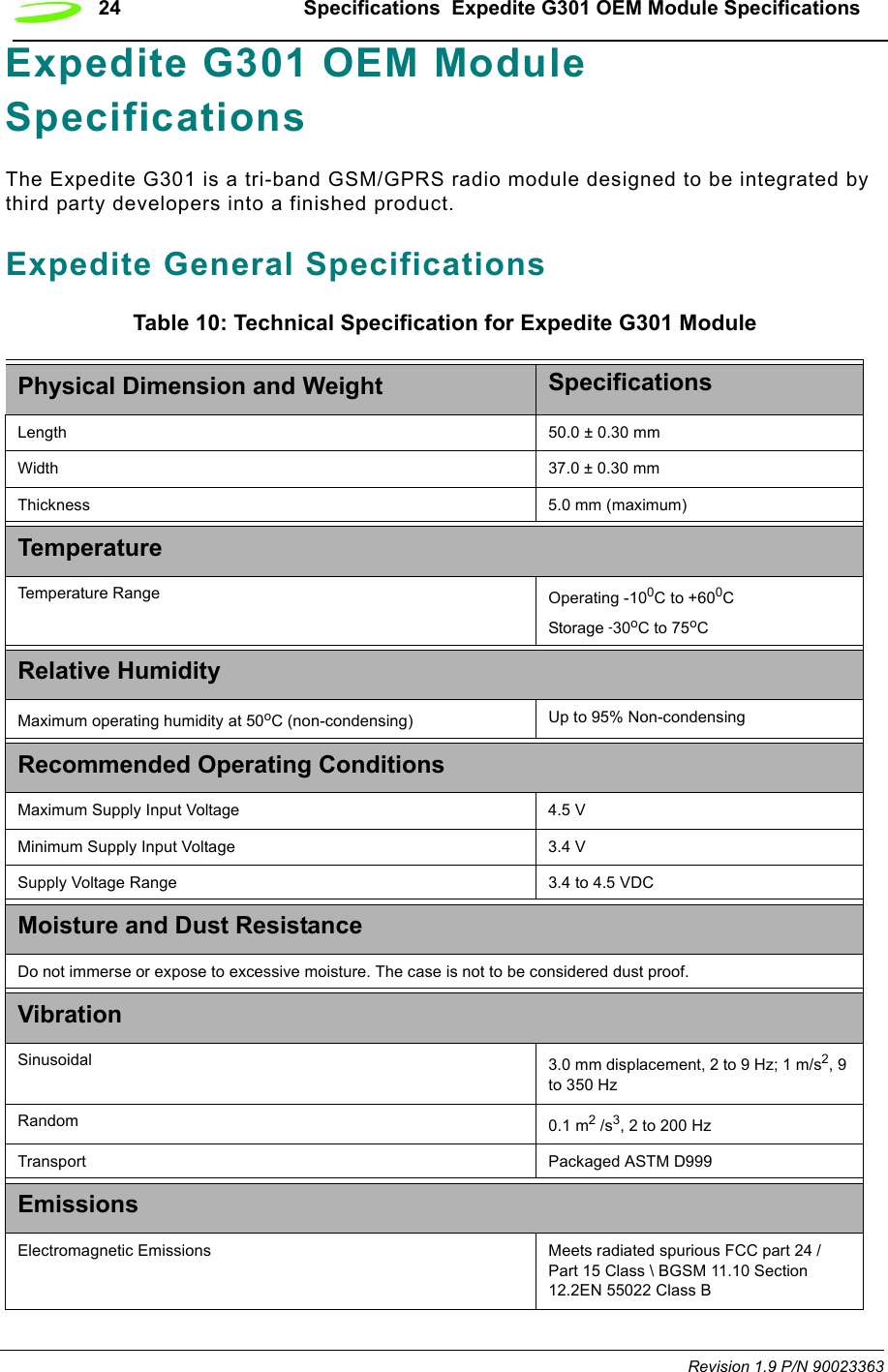
![64 AT Commands Revision 1.9 P/N 90023363Syntax: ATL[<n>]Parameters: 0, 1, 2, 3where:0 sets the speaker volume to very low1 sets the speaker volume to low2 sets the speaker volume to medium3 sets the speaker volume to highResponse: This command will return the string OK.Example: ATL3<cr>ATMDescription: ENABLE MODEM SPEAKER This command turns the modem’s speaker circuit on or off. When the modem is installed in a computer, it will use the computer’s default speaker.This command is ignored when the modem is connected to a GSM network.Syntax: ATM[<n>]Parameters: 0, 1, 2where:0 turns the speaker off1 turns the speaker on until the modem informs the terminating equipment that a carrier has been detected2 turns the speaker on while the modem is off-hookResponse: OKExample: ATM1<cr> OKATODescription: OPEN DATA MODE This command switches the modem from command mode to data mode. This command is generally used to return the modem to data mode after the user has issued the command +++AT and worked in the modem’s command mode.Syntax: ATO[0]](https://usermanual.wiki/Novatel-Wireless/NRM-EG301.Revised-Users-manual/User-Guide-315684-Page-72.png)
![AT Commands 65 P/N 90023363 Revision 1.9Parameters: 0 This parameter is the default, as well as the only parameter, and does not necessarily have to be typed with the command.Response: If connection is not successfully resumed, the modem will return the string:NO CARRIERIf connection is successfully resumed, the modem will return the string:CONNECT<text>where <text> is only displayed if the command ATX has been set to a value greater than 0.Example: ATO<cr> <Data Field to and from Modem>ATPDescription: PULSE DIAL MODE This command is used to instruct the modem to dial the next telephone number using pulse dialing. This command is a legacy command and is ignored when the modem is connected to a GSM network.Syntax: ATP<cr>Parameters: NoneResponse: This command will return the string OK.Example: ATP<cr>ATQDescription: QUIET MODE This command is used to specify whether or not the modem will sent result codes to the terminating equipment. Text sent from the modem to the terminating equipment using the ATI command will not be affected.Syntax: ATQ[<n>]Parameters: 0, 10 instructs the modem to send the result codes; this is the default.1 instructs the modem to suppress the result codes and not transmit them to the terminating equipment.Response: If this command has been set to 0, the modem’s response will be OK. If this command has been set to 1, there will be no response from the modem.Example: ATQ0<cr>](https://usermanual.wiki/Novatel-Wireless/NRM-EG301.Revised-Users-manual/User-Guide-315684-Page-73.png)
![66 AT Commands Revision 1.9 P/N 90023363ATS0Description: LISTEN MODE This command sets the number of rings the modem will wait before it will answer the incoming call. This command sets the modem’s S-register 0.Syntax: ATS0[=<n>][?]Parameters: =<n>, ?<n> is a number between 1 and 255 that represents the number of rings the modem will wait before answering the incoming call. This command sets the S-register 0 to the number specified in <n>. If this command is set to 0, the modem will never answer the incoming call.? will query the S-register and return the register’s current valueResponse: If the user has typed the command ATS0?, the modem will return the current value of the register and the string OK. For example:5OKIf the user has typed the command ATS0=<n>, the modem will only return the string OK.Example: ATS0=5<cr> answer after 5 ringsOKATS2Description: ESCAPE CHARACTER SELECTIONThe escape sequence consists of three repetitions of the escape code character, defined by S-Register 2 (default value: decimal 43(+)). The escape sequence causes the modem to go to the off-line command state from the on-line data state. After this escape sequence, the modem can accept user's AT Commands.Syntax: ATS2=<n><cr>Parameters: <n> is the decimal value of the ASCII character used as the “escape” characterResponse: OKExample: ATS2=43<cr> OK](https://usermanual.wiki/Novatel-Wireless/NRM-EG301.Revised-Users-manual/User-Guide-315684-Page-74.png)
![AT Commands 67 P/N 90023363 Revision 1.9ATS3Description: COMMAND TERMINATION CHARACTER This command sets the character that will be used as the command line termination character. The terminating character may be changed using this command. This command sets the modem’s S-register 3.Syntax: ATS3[=<n>][?]Parameters: =<n>, ?=<n> is the ASCII code number that represents the character to be used as the command line termination character. This command sets S-register 3 to the number specified in <n>. The valid values for this parameter range from 0 to 127 and the default for this S-register is 13, which is the carriage return character.? will query the S-register and return the register’s current value.Response: If the user has typed the command ATS3?, the modem will return the current value of the register and the string OK. For example:13OKIf you the user has typed the command ATS3=<n>, the modem will only return the string OK.Example: ATS3=23<cr>ATS3?<cr>ATS4Description: EOL CHARACTER SELECTION This command sets the character that will be used as the modem’s response string end-of-line character. This command sets the modem’s S-register 4.Syntax: ATS4[=<n>][?]Parameters: =<n>, ?where:=<n> is the ASCII code number that represents the character to be used as the modem’s response string end-of-line character. This command sets S-register 4 to the number specified in <n>. The valid values for this parameter range from 0 to 127 and the default for this S-register is 10, which is the line feed character.? will query the S-register and return the register’s current value.](https://usermanual.wiki/Novatel-Wireless/NRM-EG301.Revised-Users-manual/User-Guide-315684-Page-75.png)
![68 AT Commands Revision 1.9 P/N 90023363Response: If the user has typed the command ATS4?, the modem will return the current value of the register and the string OK. For example:10OKIf the user has typed the command ATS4=<n>, the modem will only return the string OK.Example: ATS4=32<cr>ATS4?<cr>ATS5Description: BACKSPACE CHARACTER This command sets the character that will be used by the command line as the backspace character; when the command line receives this character, it will erase the character immediately preceding the cursor. This command sets the modem’s S-register 5.Syntax: ATS5[=<n>][?]Parameters: =<n>, ?=<n> is the ASCII code number that represents the character to be used as the backspace character. This command sets S-register 5 to the number specified in <n>. The valid values for this parameter range from 0 to 127 and the default for this S-register is 8, which is the backspace character assigned to the Backspace key on your keyboard.? will query the S-register and return the register’s current value.Response: If the user has typed the command ATS5?, the modem will return the current value of the register and the string OK. For example:8OKIf the user has typed the command ATS5=<n>, the modem will only return the string OK.Example: ATS5=110<cr>ATS5?<cr>](https://usermanual.wiki/Novatel-Wireless/NRM-EG301.Revised-Users-manual/User-Guide-315684-Page-76.png)
![AT Commands 69 P/N 90023363 Revision 1.9ATS6Description: CONNECTION HOLD OFF TIMER This command sets the number of seconds the modem will wait before it will begin blind dialing (dialing without checking for a dial tone). This command sets the modem’s S-register 6.This command is ignored when the modem is connected to a GSM network.Syntax: ATS6[=<n>][?]Parameters: =<n>, ?=<n> is a number between 0 and 255 that represents the number of seconds the modem will wait before blind dialing an outbound call. This command sets S-register 6 to the number specified in <n>. The default value for this register is 2.? will query the S-register and return the register’s current value.Response: If the user has typed the command ATS6?, the modem will return the current value of the register and the string OK. For example:4OKIf the user has typed the command ATS6=<n>, the modem will only return the string OK.Example: ATS6=4<cr>ATS7Description: CONNECTION TIMEOUT This command sets the number of seconds the modem will wait for the connection to complete during an inbound or outgoing call, before it stops attempting to connect. This command sets the modem’s S-register 7.Syntax: ATS7[=<n>][?]Parameters: =<n>, ?=<n> is a number between 0 and 255 that represents the number of seconds the modem will wait before stopping the connection attempt. This command sets S-register 7 to the number specified in <n>. The default value for this register is 60.? will query the S-register and return the register’s current value.](https://usermanual.wiki/Novatel-Wireless/NRM-EG301.Revised-Users-manual/User-Guide-315684-Page-77.png)
![70 AT Commands Revision 1.9 P/N 90023363Response: If the user has typed the command ATS7?, the modem will return the current value of the register and the string OK. For example:4OKIf the user has typed the command ATS7=<n>, the modem will only return the string OK.Example: ATS7=4<cr>ATS8Description: COMMA DIAL MODIFIERThis command sets the value of the comma dial modifier, in seconds. The comma dial modifier is placed in-between the digits of the telephone number you wish to call to provide a pause. This might be used when dialing 9 to get an outside telephone line. This command sets the modem’s S-register 8.This command is ignored when the modem is connected to a GSM network.Syntax: ATS8[=<n>][?]Parameters: =<n>, ?=<n> is a number between 1 and 255 that represents the number of seconds the modem will wait to dial the remaining digits in the telephone number. This command sets S-register 8 to the number specified in <n>. If this command is set to 0, the there will be no pause when the comma (,) is encountered. The default is set to 2.? will query the S-register and return the register’s current value.Response: If the user has typed the command ATS8?, the modem will return the current value of the register and the string OK. For example:2OKIf the user has typed the command ATS8=<n>, the modem will only return the string OK.Example: ATS8=2<cr>ATS10Description: DATA CARRIER TIMEOUT This command sets the amount of time, in 1/10th secs, the modem will wait before returning on-hook, if it can no longer detect the data carrier. This command sets the modem’s S-register 10.](https://usermanual.wiki/Novatel-Wireless/NRM-EG301.Revised-Users-manual/User-Guide-315684-Page-78.png)
![AT Commands 71 P/N 90023363 Revision 1.9Syntax: ATS10[=<n>][?]Parameters: =<n>, ?=<n> is a number between 1 and 255 that represents the number in 1/10th secs the modem will wait before going on-hook, if it no longer detects a data carrier. This command sets S-register 10 to the number specified in <n>. The default value for this register is 15.? will query the S-register and return the register’s current value.Response: If the user has typed the command ATS10?, the modem will return the current value of the register and the string OK. For example:25OKIf the user has typed the command ATS10=<n>, the modem will only return the string OK.Example: ATS10=25<cr>ATS12Description: ESCAPE SEQUENCE GUARD SELECTIONThe Escape sequence guard time selection register, S-Register 12, is not actively used and will report a “0” when queried. Normally the guard time is used to discriminate between valid and invalid occurrences of the escape sequence. The duration between escape codes must also be within the guard time. After the modem recognizes a valid escape sequence, an "OK" result code is returned. If an escape sequence is valid, the modem will exit data mode and enter command mode. The ATO command is used to go back to on-line data state.Syntax: ATS12=<n><cr>Parameters: <n> Regardless of the value entered, 0 will always be used.Response: OKExample: ATS12=10<cr>ATTDescription: TONE DIALING This command is used to instruct the modem to dial the next telephone number using tone dialing. This command is a legacy command and is ignored when the modem is connected to a GSM network.Syntax: ATT<cr>Parameters: None](https://usermanual.wiki/Novatel-Wireless/NRM-EG301.Revised-Users-manual/User-Guide-315684-Page-79.png)
![72 AT Commands Revision 1.9 P/N 90023363Response: This command will return the string OK.Example: ATT<cr> OKATVDescription: VERBOSE This command displays the modem’s result codes in terse or verbose form.In terse form, all result codes are represented by an error code number and all text messages have only a carriage return (<cr>) character appended to them.In verbose form, all result codes are returned as words or sentences and all text messages have a carriage return-line feed (<cr><lf>) character pair before and after the text message.Syntax: ATV[<n>]Parameters: 0, 10 will set the response format to terse1 will set the response format to verboseResponse: If the command has been set to 0, it will return the response:0If the command has been set to 1, it will return the response:OKExample: ATV=1<cr> OKATXDescription: ACCESS CONTROL This command will specify whether or not the modem will attempt to detect a dial tone and busy signal, and what type of result code is returned.Syntax: ATX[<n>]Parameters: 0, 1, 2, 3, 4where:0 will set the modem to not detect the dial tone or the busy signal and return the result code CONNECT.1 will set the modem to not detect the dial tone or the busy signal and return the result code CONNECT<additional session-specific text>.](https://usermanual.wiki/Novatel-Wireless/NRM-EG301.Revised-Users-manual/User-Guide-315684-Page-80.png)
![AT Commands 73 P/N 90023363 Revision 1.92 will set the modem to detect the dial tone, but not the busy signal. It will also return the result code CONNECT<additional session-specific text>.3 will set the modem not to detect the dial tone, but detect the busy signal. It will also return the result code CONNECT<additional session-specific text>.4 will set the modem to detect both the dial tone and the busy signal and return the result code CONNECT<additional session-specific text>.Response: This command will return the string OK.Example: ATX4<cr>ATZDescription: RESET PARAMETERS TO SAVED SETTINGS This command uses the user-defined modem settings profile stored in the non-volatile memory as the active profile. If the user-defined profile is invalid, the modem will use the factory default settings. Any additional commands on the same command line are ignored. This command uses the profile created by the AT&W command.Syntax: ATZ[0]Parameters: 0 This parameter is the default, as well as the only parameter, and does not necessarily have to be typed with the command.Response: This command will return the string OK.](https://usermanual.wiki/Novatel-Wireless/NRM-EG301.Revised-Users-manual/User-Guide-315684-Page-81.png)
![74 AT Commands Revision 1.9 P/N 90023363AT&CDescription: DATA CARRIER DETECT (DCD) MODE This command sets the data carrier detect mode.Syntax: AT&C[<n>]Parameters: 0, 10 sets the data carrier detect so it is always on1 sets the data carrier detect so it is only on in the presence of a data carrierResponse: This command will return the string OK.Example: AT&C1<cr>AT&DDescription: DATA TERMINAL READY (DTR) CONTROLThis command defines how the modem responds, while in data mode, to the data terminal ready (DTR) circuit changing state from ON to OFF.Syntax: AT&D[<n>]Parameters: 0, 1, 20 instructs the modem to ignore the data terminal ready state1 instructs the modem to change to command mode, while remaining connected to the call2 instructs the modem to disconnect from the call and then change to command mode. While the data terminal ready state is set to off, the modem’s auto-answer function is also off.Response: This command will return the string OK.Example: AT&D2<cr>AT&FDescription: RESTORE FACTORY DEFAULT SETTINGSThis command will return all the modem settings to their factory default setting.Syntax: AT&F[0]Parameters: 0 This parameter is the default, as well as the only parameter, and does not necessarily have to be typed with the command.Response: <cr>hello<cr><LF><LF>OKExample: AT&F0<cr>](https://usermanual.wiki/Novatel-Wireless/NRM-EG301.Revised-Users-manual/User-Guide-315684-Page-82.png)
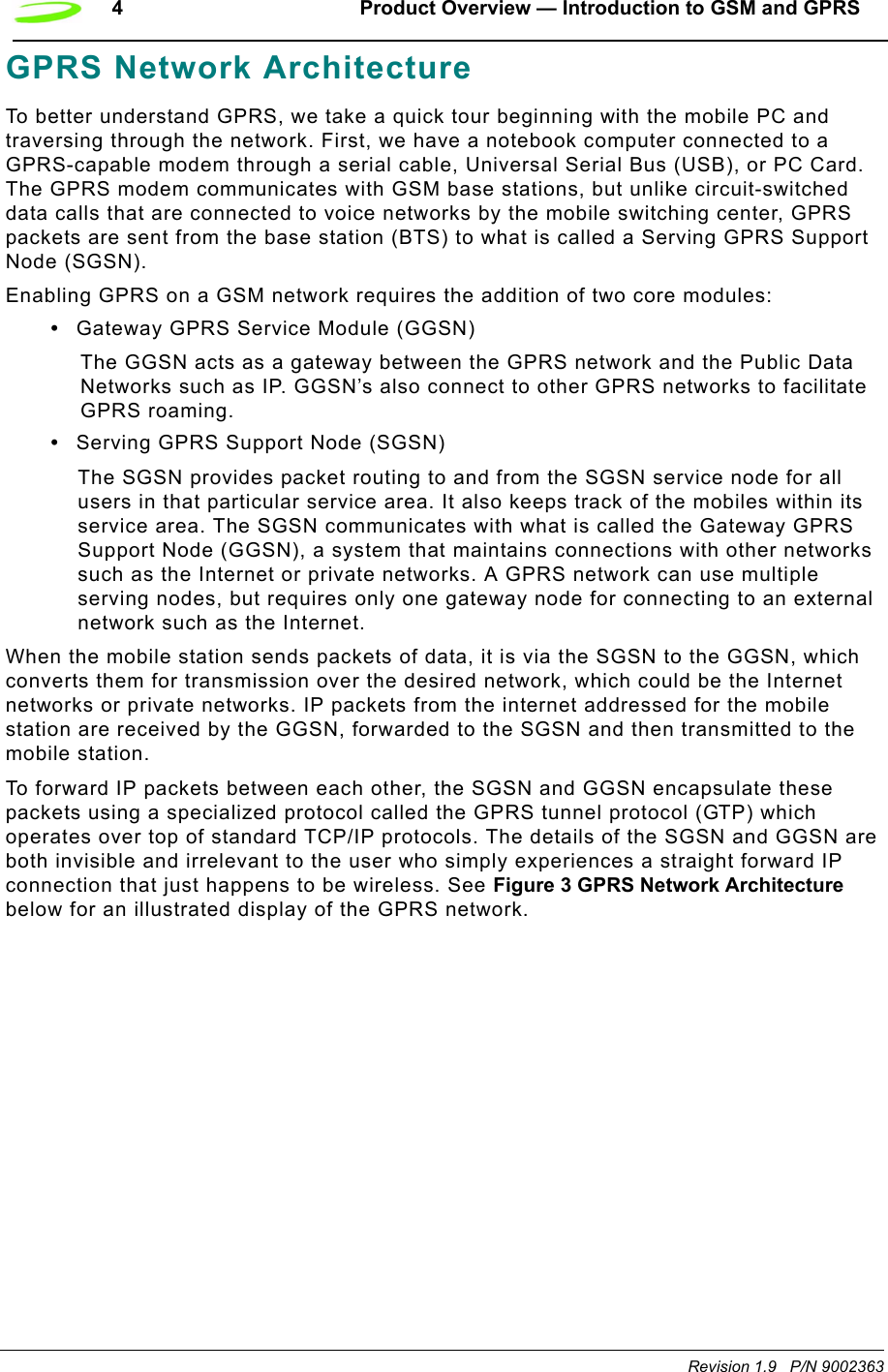
![AT Commands 75 P/N 90023363 Revision 1.9AT&VDescription: VIEW ACTIVE PROFILE This command will display the active profile settings on the terminating equipment.Syntax: AT&V[0]Parameters: 0 This parameter is the default, as well as the only parameter, and does not necessarily have to be typed with the command.Response: The response will be a listing of the current configuration followed by the string OK. For example ACTIVE PROFILE :E1 L1 M1 Q0 V1 X4 &C1 &D2S0:0 S2:43 S3:13 S4:10 S5:8 S6:2 S7:60 S8:2 S10:15 S12:+CBST: 7,0,1+CSMS: 0+CRLP: 61,61,48,6,0,3+CRC: 0+CR: 0+FCLASS: 0+IFC: 2,2+IMODE: 0+ICF: 3,3+DR: 0+CMGF: 0+CSDH: 0+CNMI: 2,1,0,0,0+ILRR: 0+IPR: 115200+DS: 3,0,512,20+CMEE: 0+CREG: 0+CCUG: 0,0,0+CLIP: 0+COLP: 0+CCWA: 0+CAOC: 1+CLIR: 0+CSCA: "+44385016005",145+CSMP: 17,167OKExample: AT&V<cr>](https://usermanual.wiki/Novatel-Wireless/NRM-EG301.Revised-Users-manual/User-Guide-315684-Page-83.png)
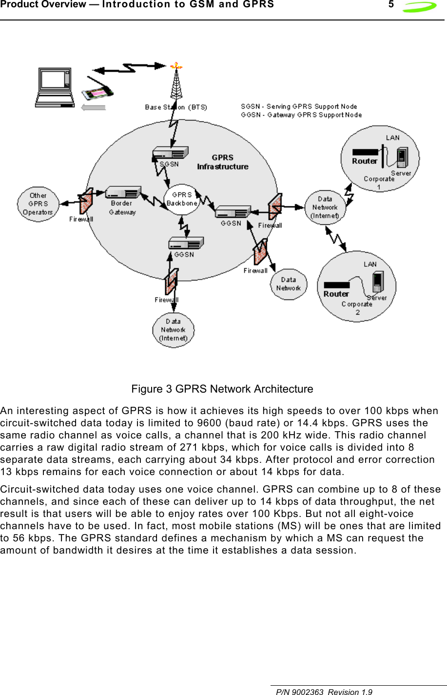
![76 AT Commands Revision 1.9 P/N 90023363AT&WDescription: SAVE MODEM PROFILE (SETTINGS)This command stores the active modem settings profile in the modem’s non-volatile memory. This stored profile can later be retrieved using the ATZ command.Syntax: AT&W[0]Parameters: NoneResponse: This command will return the string OK.Example: AT&W0<cr>AT+CACMDescription: ACCUMULATED CALL METER (RESET OR QUERY)This command reads or resets the Advice of Charge related accumulated call meter (ACM) value in SIM file EF(ACM). ACM contains the total number of home units for both the current and preceding calls. Syntax: AT+CACM=[<password>] (Reset)Parameters: passwd SIM PIN2Response: <acm> string type; three bytes of the current ACM value in hexadecimal format (e.g. "00001E" indicates decimal value 30)Example: Input ResponseQuery AT+CACM? 00037FReset AT+CACM=opensesame OKTe s t AT+CACM=? OKAT+CALMDescription: ALERT SOUND MODEThis command sets the sound actions to to alert the user. This can be used to enable or disable the sound utilized to alert the user. Available in Command mode only.Syntax: AT+CALM=<mode>Parameters: 0 Normal Mode<mode> 0 normal mode1 silent mode (all sounds from ME are prevented)Response: OK](https://usermanual.wiki/Novatel-Wireless/NRM-EG301.Revised-Users-manual/User-Guide-315684-Page-84.png)
![AT Commands 77 P/N 90023363 Revision 1.9Example:Query +CALM: <mode>+CME ERROR: <err>Tes t +CALM: (list of supported <mode>s)+CME ERROR: <err>AT+CAMMDescription: ACCUMULATED CALL METER MAXIMUMThis command sets the Advice of Charge related accumulated call meter maximum value in SIM file EF(ACMmax). ACMmax contains the maximum number of home units allowed to be consumed by the subscriber.Syntax: AT+CAMM=[<ACMMAX>[,<PASSWD>]]Parameters: ACMMAX string type; three bytes, 000001-FFFFFF, of the max. ACM value in hexa-decimal format (e.g. "00001E" indicates decimal value 30). A value of 000000 will disable ACMmax feature.PASSWD SIM PIN2Example: Input ResponseQuery AT+CAMM? 00037FSet AT+CAMM=000400 OKTes t AT+CAMM=? OKAT+CAOCDescription: ADVICE OF CHANGEThis command, when active, sends an unsolicited result code when the current call meter (CCM) value changes, this will not be reported more than once every 10 secs.Syntax: AT+CAOC=<mode>Parameters: 0, 10query CCM value1 deactivate the unsolicited reporting of CCM value2 activate the unsolicited reporting of CCM valueExample: Input ResponseQuery AT+CAOC? Current mode OKSet AT+CAOC=1 OKTes t AT+CAOC=? List of possible selectIons](https://usermanual.wiki/Novatel-Wireless/NRM-EG301.Revised-Users-manual/User-Guide-315684-Page-85.png)
![AT Commands 79 P/N 90023363 Revision 1.9AT+CBSTDescription: Bearer Service TypeThis command selects the bearer service <name> with data rate <speed>, and the connection element <ce> to be used when data calls are originated.Syntax: AT+CBST=[<speed>] [,<name>[,<ce>]]]Parameters:<speed> 0 autobalancing1 300 bps (V.21)2 1200 bps(V.22)3 1200/75 bps (V.23)4 2400 bps (V22bis)5 2400 bps(V.26ter)6 4800 bps(V.32)7 9600 bps (V.32)12 9600 bps (V.34)14 14400 bps (V.34)65 300 bps (V.110)66 1200 bps (V.110 or X.31 flag stuffing)68 2400 bps (V.110 or X.31 flag stuffing)70 4800 bps (V.110 or X.31 flag stuffing)71 9600 bps (V.110 or X.31 flag stuffing)75 14400 bps (V.110 or X.31 flag stuffing)<name> 0 asynchronous modem2 PAD access (asynchronous)<ce> 0 transparent1 non-transparentExample: Query ResponseQuery AT+CBST? Current mode OKSet AT+CBST=7,2,0 OKTes t AT+CBST=? List of possible selectIon](https://usermanual.wiki/Novatel-Wireless/NRM-EG301.Revised-Users-manual/User-Guide-315684-Page-87.png)
![80 AT Commands Revision 1.9 P/N 90023363AT+CCFCDescription: CALL FORWARDThis command controls the call forwarding supplementary service. Registration, erasure, activation, deactivation, and status query are supported. Only <reas> and <mode> should be entered with mode (0-2,4).Syntax: AT+CCFC = <reas>, <mode>[, <number> [, <type> [,<class> [, <subaddr> [,<satype> [,<time>]]]]]]Parameters:<reas> 0 unconditional1 mobile busy2 no reply3 not reachable4 all call forwarding (0-3)5 all conditional call forwarding (1-3)<mode> 0 disable1 enable2 query status3registration4 erasure<number> string type phone number of forwarding address in format specified by <type> asynchronous modem<type> type of address in integer format; default 145 when dialing string includes international access code character "+", otherwise 129<subaddr> string type subaddress of format specified by <satype><satype> type of subaddress in integer; default 128<class> 1 voice2data4fax7all classes<time> time, rounded to a multiple of 5 secs](https://usermanual.wiki/Novatel-Wireless/NRM-EG301.Revised-Users-manual/User-Guide-315684-Page-88.png)
![AT Commands 81 P/N 90023363 Revision 1.9<status> 0 not active1activeResponse: If <mode><>2 and command successfulOKIf there is a network error:+CCFC: 0, 0If <mode>=2 and command successful (only in connection with <reas> 0 – 3)For registered call forward numbers:+CCFC: <status>, <class1>[, <number>, <type> [, <time>]] [<cr><LF>+CCFC: ....] OKIf no call forward numbers are registered (and therefore all classes are inactive):+CCFC: <status>, <class> OKwhere <status>=0 and <class>=7If error is related to ME functionality:+CME ERROR: <err>Example: Input OutputQuery AT+CCFC? Current mode OKSet AT+CCFC=0,1,,,,,, OKTes t AT+CCFC=? List of possible selectIonAT+CCLKDescription: CLOCK SETTING, TIME OF DAY, DATEThis command is used to set the local time for the device as well as determining the current time. ME does not support time zone indication.Syntax: AT+CCLK=<time>Parameters:<time> string type value; format is "yy/MM/dd,hh:mm:ss”; where characters indicate year (two last digits), month, day, hour, minutes and seconds. e.i 22:10:00 GMT equals to "94/05/06,22:10:00"](https://usermanual.wiki/Novatel-Wireless/NRM-EG301.Revised-Users-manual/User-Guide-315684-Page-89.png)
![82 AT Commands Revision 1.9 P/N 90023363Response:Query +CCLK: <time>+CME ERROR: <err>Te s t OKAT+CCUGDescription: CLOSER USER GROUP This command sets the Closed User Group supplementary service parameters as a default adjustment for all following calls.Syntax: AT+CCUG=[<n>] [,<index>[,<info>]]]Parameters:<speed> 0disable CUG1 enable CUG71 9600 bps (V.110 or X.31 flag stuffing)<index> 0...9 CUG index10 no index (preferred CUG taken from subscriber data)<info> 0 no information1 suppress OA (Outgoing Access)2 suppress preferential CUG3 suppress OA and preferential CUGResponse: +CCUG: <n>,<index>,<info> OKIf error is related to ME functionality:+CME ERROR: <err>Example: Input OutputQuery AT+CCUG? Current mode OKSet AT+CCUG=0,1,,,,,, OKTe s t AT+CCUG=? List of possible selectionsAT+CCWADescription: CALL WAITINGThis command controls the Call Waiting supplementary service. Activation, deactivation and status query are supported.Syntax: AT+CCWA=[<n>] [,<mode>[,<class>]]]Parameters:](https://usermanual.wiki/Novatel-Wireless/NRM-EG301.Revised-Users-manual/User-Guide-315684-Page-90.png)
![AT Commands 83 P/N 90023363 Revision 1.9Parameters:<n> 0 disable unsolicited result code 1 enable presentation of an unsolicited result code71 9600 bps (V.110 or X.31 flag stuffing)<mode> when <mode> parameter not given, network is not interrogated0disable1 enable2 query status<class> is a sum of integers each representing a class of information1 voice (telephony)2 data (bearer service)4 fax (teleservice)7 default (equals to all classes)<status> 0 not active1 enableExample: Input OutputQuery AT+CCWA? Current selection OKSet AT+CCWA=1,1,1,1 OKTes t AT+CCWA=? List of possible selectionsUnsolicited Response: When the presentation Call Waiting at the MODEM is enabled (and Call Waiting is enabled) and a terminating call set up has attempted during an established call, an unsolicited result code is returned:+CCWA: <number>,<type>,<class>[,<alpha>]<number> string type phone number of calling address in format specified by <type><type> type of address octet in integer format; 145 when dialing string includes international access code character "+", otherwise 129<alpha> optional string type alphanumeric representation of <number> corresponding to the entry found in a phone book](https://usermanual.wiki/Novatel-Wireless/NRM-EG301.Revised-Users-manual/User-Guide-315684-Page-91.png)
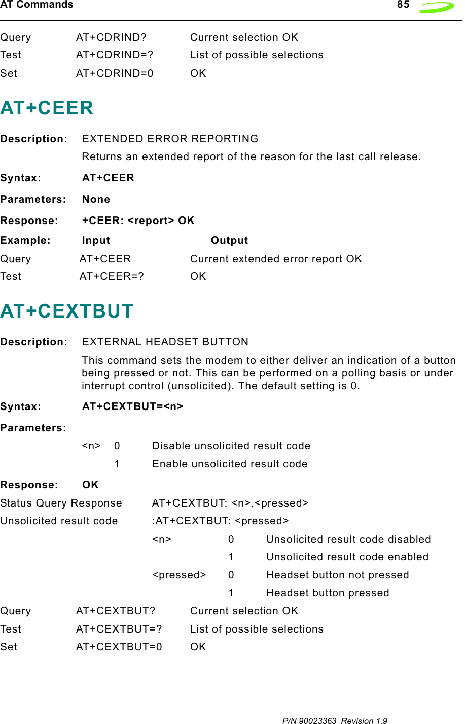
![86 AT Commands Revision 1.9 P/N 90023363AT+CEXTHS Description: EXTERNAL HEADSET This command sets the alert mechanism and also permits polling for the current state of the headset jack, either present or absent.Syntax: AT+CEXTHS=<n>Parameters:<n> 0 Disable unsolicited result code1 Enable unsolicited result codeResponse: OKStatus Query Response +CEXTHS: <n>,<attach><n> 0 Unsolicited result code disabled1 Unsolicited result code enabled<attach> 0 unattached external headset1 attached external headsetUnsolicited result code: +CEXTHS: <attach>Query AT+CEXTHS? Current selection OKTest AT+CEXTHS=? List of possible selectionsSet AT+CEXTHS=0 OKAT+CFUNDescription: SET FUNCTIONALITY LEVELSets the current functionality of the device. Typically used on phones and voice applications. Support for this command will be hardware dependant. For UPGRADE_SYSTEM_2, settings above 1 are not supported.Syntax: AT+CFUN=<fun>[,<rst>]Parameters:<fun> 0 minimum functionality1 full functionality (Default)2 disable phone transmit RF circuits only3 disable phone receive RF circuits only4 disable phone both transmit and receive RF circuits5..127 reserved for manufacturers as intermediate states between full and minimum functionality<rst> 0 do not reset the ME before setting it to <fun> power level](https://usermanual.wiki/Novatel-Wireless/NRM-EG301.Revised-Users-manual/User-Guide-315684-Page-94.png)
![AT Commands 87 P/N 90023363 Revision 1.9Response:Query AT+CFUN? Current selection OKTest AT+CFUN=? List of possible selectionsSet AT+CFUN=1 OKAT+CGACTDescription: PDP CONTEXT ACTIVATE / DEACTIVATEThis execution command is used to activate or deactivate the specified PDP context(s).Syntax: AT+CGACT=[<state>[,<cid>[,<cid>[,…]]]]Parameters:<cid> a numeric parameter which specifies a particular PDP context definition (see +CGDCONT command). The following parameters are defined in GSM 03.60 -<state> indicates the state of PDP context activation0 – deactivated1 – activatedOther values are reserved and will result in an ERROR response to the execution command.Response: AT+CGACT?+CGACT: <cid>,<state>[<cr><LF>+CGACT: <cid>,<state>[…]]AT+CGAPNRThis command reads APNs from the store. The command can be provided with an absolute APN index to read or an index range for a group of APNs to fetch.Description: Read records from the APN store.Syntax: AT+CGAPNR:<index1>,[<index2>]Parameters: <index1> index of APN record to read or start index of read list<index2> stop index of record listResponse: User specifies index of record to read or range of records to display. Returns the data contained within the specified APN record(s). Entries that are invalid are not shown.+CGAPNR:<index>,<apn>,<usage>,<description>,<user>,<password>,OKExample: AT+CGAPNR=<index1>,[<index2>]Test: AT+CGAPNR=? Returns the parameter for the read operation.](https://usermanual.wiki/Novatel-Wireless/NRM-EG301.Revised-Users-manual/User-Guide-315684-Page-95.png)
![88 AT Commands Revision 1.9 P/N 90023363AT+CGAPNWThis command writes or deletes an APN specified by a given index number. The user provides the description of the APN to write. The minimum description features an index in the case of a delete event or an index and an APN in the case of a write event.Description: Write/delete record from the APN store.Syntax: AT+CGAPNW:<index>[<apn>,[<....>]]Parameters: <index> index of APN records to read<apn> APN string<usage> usage for this APN (1=General IP, 2=WAP)<description> description string<user> user name string<password> password stringResponse: Writes supplied data to the specified APN record in the store. If only the index field is supplied, the specified record is deleted.OKA CME error if the index is invalid or entered data is invalid:+CME ERROR:invalid indexERROR+CME ERROR: invalid input value. ERRORExample: AT+CGAPNW:<index>[<apn>,[<usage>,[<description>[<user>,<password>]]]]]](https://usermanual.wiki/Novatel-Wireless/NRM-EG301.Revised-Users-manual/User-Guide-315684-Page-96.png)
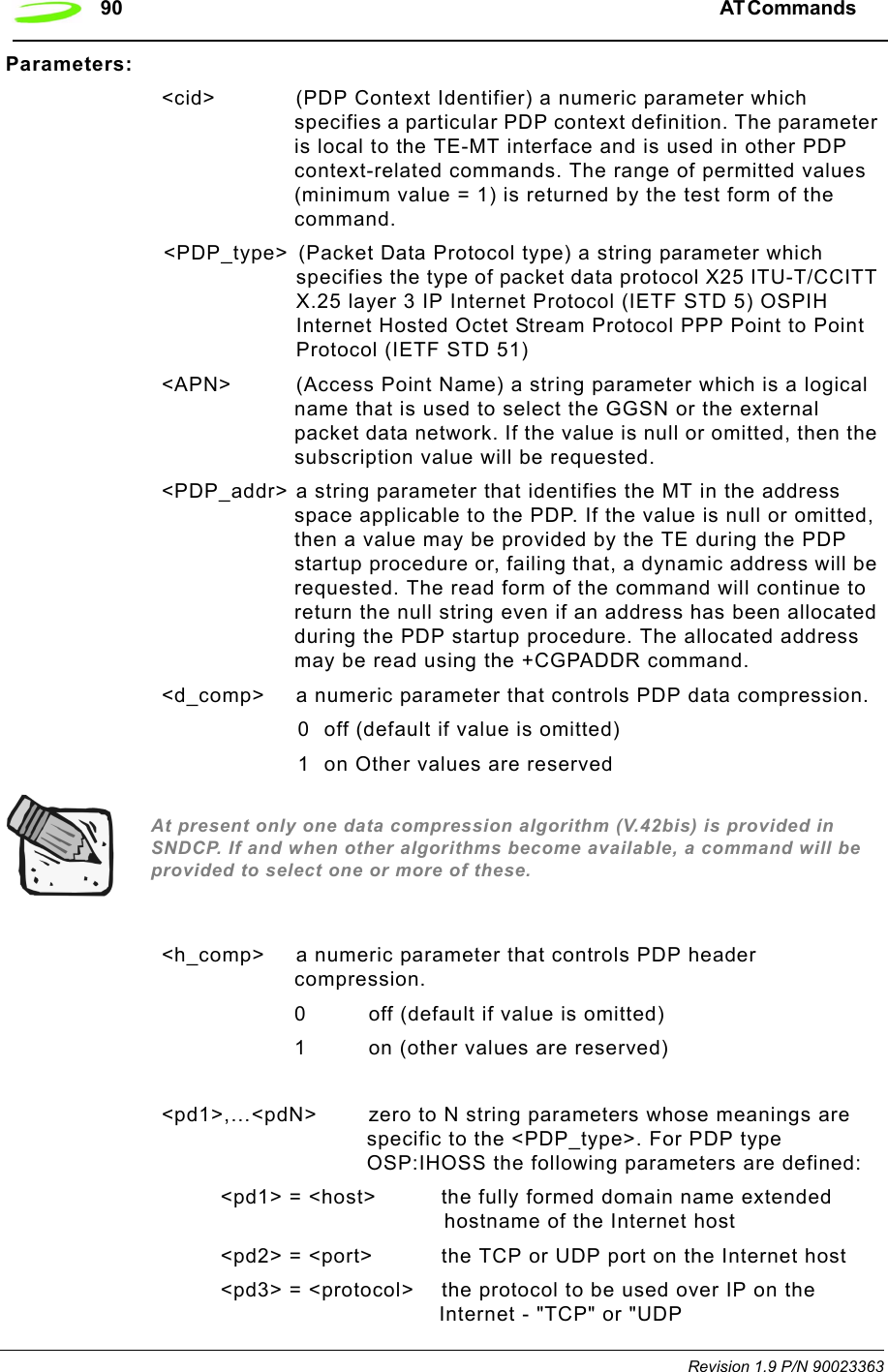
![AT Commands 89 P/N 90023363 Revision 1.9AT+CGATTDescription: GPRS ATTACHED OR DEATTACHEDThis execution command is used to attach to, or detach the MT from, the GPRS service.Syntax: AT+CGATT= [<state>]Parameters: <state> indicates the GPRS attach state0 – attached1 – detachedOther values are reserved and will result in an ERROR response to the execution command.Response: +CGATT:<state>Query AT+CGATT? OKTest AT+CGATT=?Set AT+CGATT=0AT+CGCLASSDescription: GPRS MOBILE STATION CLASSClass A and B are not supported by this GPRS solution. Class C is only supported for <class> values of “CG” and “CC”Syntax: AT+CGCLASS= [<class>]Parameters: <class> a string parameter which indicates the GPRS mobile class (in descending order of functionality)A class A (highest)Bclass BCG class C in GPRS only modeCC class C in circuit switched only mode (lowest)Response: +CGCLASS: <class>AT+CGDCONTDescription: PDP CONTEXT DEFINEDThis set command specifies PDP context parameter values for a PDP context identified by the (local) context identification parameter <cid>.Define the PDP context and APN address.Syntax: AT+CGDCONT=[<cid>[,<PDP_type>[,<APN>[,<PDP_addr>[,<d_comp>[,<h_comp>[,<pd1>[,…[,pdN]]]]]]]]]](https://usermanual.wiki/Novatel-Wireless/NRM-EG301.Revised-Users-manual/User-Guide-315684-Page-97.png)
![AT Commands 91 P/N 90023363 Revision 1.9Example: AT+CGDCONT? +CGDCONT: <cid>,<PDP_type>,<APN>,<PDP_addr>,<data_comp>,<head_comp>[,<pd1>[,…[,pdN]]] [<cr><LF>+CGDCONT: <cid>,<PDP_type>,<APN>,<PDP_addr>,<data_comp>,<head_comp>[,<pd1>[,…[,pdN]]] AT+CGEREPDescription: UNSOLICITED EVENT REPORTING CONTROLSyntax: AT+CGEREP=[<mode>[,<bfr>]]Parameters:<mode> 0 buffer unsolicited result codes in the MT; if MT result code buffer is full, the oldest ones can be discarded. No codes are forwarded to the TE.1 discard unsolicited result codes when MT-TE link is reserved (e.g. in online data mode); otherwise forward them directly to the TE2 buffer unsolicited result codes in the MT when MT?TE link is reserved (e.g. in online data mode) and flush them to the TE when MT-TE link becomes available; otherwise forward them directly to the TE<bfr> 0 MT buffer of unsolicited result codes defined within this command is cleared when <mode> 1 or 2 is entered1 MT buffer of unsolicited result codes defined within this command is flushed to the TE when <mode> 1 or 2 is entered (OK response shall be given before flushing the codes)Unsolicited Response:+CGEV: NW DEACT <PDP_type>,<PDP_addr>[,<cid>]+CGEV: ME DEACT <PDP_type>,<PDP_addr>[,<cid>]+CGEV: NW DETACH+CGEV: ME DETACH+CGEV: ME CLASS <class><PDP_type>Packet Data Protocol type (see +CGDCONT command)<PDP_addr>Packet Data Protocol address (see +CGDCONT command}<cid> Context Id (see +CGDCONT command). Note: <cid> only given if known to the MT.<class> GPRS mobile class (see +CGCLASS command)Query AT+CGEREP? OK](https://usermanual.wiki/Novatel-Wireless/NRM-EG301.Revised-Users-manual/User-Guide-315684-Page-99.png)
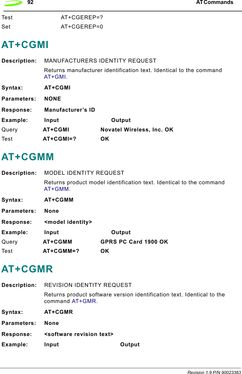
![AT Commands 93 P/N 90023363 Revision 1.9Query A T + C G M R ? S o f t w a r e V e r s i o n : P N 1 6 0 - 0 3 0 0 Date: May 23 2001, Time: 14:17:39. OKTes t AT+CGMR=? OKAT+CGOIDescription: GLOBAL IDENTITY REQUESTReports one or more lines of information text which permit the user to identify the device, based on the ISO system for registering unique object identifiers. Identical to the command AT+GOI.Syntax: AT+CGOIParameters: NoneResponse: Identifier of device type.AT+CGPADDRDescription: SHOW PDP ADDRESSThis command dictates the behavior of PPP in the ME but not the behavior of any other GPRS-enabled foreground layer, e.g. browser.Syntax: AT+CGPADDR=[<cid>[,<cid>[,…]]]Parameters:<cid> a numeric parameter which specifies a particular PDP context definition (see +CGDCONT command). If no <cid> is specified, the addresses for all defined contexts are returned.<PDP_addr> a string that identifies the MT in the address space applicable to the PDP. The address may be static or dynamic. For a static address, it will be the one set by the +CGDCONT command when the context was defined. For a dynamic address it will be the one assigned during the last PDP context activation that used the context definition referred to by <cid>. <PDP_address> is omitted if none is available.Response: +CGPADDR: <cid>,<PDP_addr>[<cr><LF>+CGPADDR: <cid>,<PDP_addr>AT+CGQMINDescription: QUALITY OF SERVICE PROFILE (MINIMUM ACCEPTABLE)](https://usermanual.wiki/Novatel-Wireless/NRM-EG301.Revised-Users-manual/User-Guide-315684-Page-101.png)
![94 AT Commands Revision 1.9 P/N 90023363Get current quality of service profile. This reports the minimum quality standard that will be used by the device / network.Syntax: AT+CGQMIN=[<cid>[,<precedence>[,<delay>[,<reliability>[,<peak>[,<mean>]]<cid> a numeric parameter which specifies a particular PDP context definition (see +CGDCONT command). The following parameters are defined in GSM 03.60<precedence> a numeric parameter which specifies the precedence class<delay> a numeric parameter which specifies the delay class<reliability> a numeric parameter which specifies the reliability class<peak> a numeric parameter which specifies the peak throughput class<mean> a numeric parameter which specifies the mean throughput classResponse: AT+CGQMIN?+CGQMIN: <cid>,<precedence>,<delay>,<reliability>,<peak>,<mean>[<cr><LF>+CGQMIN: <cid>,<precedence>,<delay>,<reliability>,<peak>,<mean>[…]]Query AT+CGQMIN? Current selection OKTest AT+CGQMIN=? List of possible selectionsSet AT+CGQMIN=<n> OKAT+CGQREQDescription: REQUEST QUALITY OF SERVICE PROFILERequest quality of service from carrier.Syntax: AT+CGQREQ=[<cid>[,<precedence>[,<delay>[,<reliability.>[,<peak>[,<mean>]]]]]]Parameters:<cid> a numeric parameter which specifies a particular PDP context definition (see +CGDCONT command). The following parameters are defined in GSM 03.60 -<precedence> a numeric parameter which specifies the precedence class<delay> a numeric parameter which specifies the delay class<reliability> a numeric parameter which specifies the reliability class<peak> a numeric parameter which specifies the peak throughput class](https://usermanual.wiki/Novatel-Wireless/NRM-EG301.Revised-Users-manual/User-Guide-315684-Page-102.png)
![AT Commands 95 P/N 90023363 Revision 1.9<mean> a numeric parameter which specifies the mean throughput classResponse: +CGQREQ:<cid>,<precedence>,<delay>,<reliability>,<peak>,<mean>[<cr><LF>+CGQREQ: <cid>,<precedence>,<delay>,<reliability>,<peak>,<mean>[…]]AT+CGREGDescription: GPRS NETWORK REGISTRATION STATUS This set command returns the status of an unsolicited result code.Syntax: AT+CGREG=[<n>]Parameters:<n> 0 disable network registration unsolicited result code1 enable network registration unsolicited result code +CGREG: <stat>2 enable network registration and location information unsolicited result code +CGREG: <stat>[,<lac>,<ci>]Response: (Read Response)+CGREG: <n>,<stat>[,<lac>,<ci>]+CME ERROR: <err><n> 0 disable network registration unsolicited result code1 enable network registration unsolicited result code +CGREG: <stat>2 enable network registration and location information unsolicited result code +CGREG: <stat>[,<lac>,<ci>]<stat> 0 device is not registered, ME is not currently searching a new operator to register to1 device is registered<lac> string type; two byte location area code in hexadecimal format (e.g. "00C3" equals 195 in decimal)<ci> string type; two byte cell ID in hexadecimal formatQuery AT+CGREG? Current selection OKTest AT+CGREG=? List of possible selectionsSet AT+CGREG=<n> OKAT+CGSMSDescription: SERVICE SELECTION FOR MO SMS MESSAGES](https://usermanual.wiki/Novatel-Wireless/NRM-EG301.Revised-Users-manual/User-Guide-315684-Page-103.png)
![96 AT Commands Revision 1.9 P/N 90023363This set command is used to specify the service or service preference that the MT will use to send MO SMS messages.Syntax: AT+CGSMS=[<service>]Parameters:<service> a numeric parameter which indicates the service or service preference to be used. The circuit switched service route is the default method.0GPRS1 circuit switched2 GPRS preferred (use CSD if GPRS not available)2 CSD preferred (use GPRS if CSD not available)Response: (Read Response)+CGSMS: [<service>]<cr> +CME ERROR: <err> <service> see above.<n> 0 disable network registration unsolicited result code1 enable network registration unsolicited result code +CGREG: <stat>2 enable network registration and location information unsolicited result code +CGREG: <stat>[,<lac>,<ci>]<stat> 0 device is not registered, ME is not currently searching a new operator to register to1 device is registered<lac> string type; two byte location area code in hexadecimal format (e.g. "00C3" equals 195 in decimal)<ci> string type; two byte cell ID in hexadecimal formatAT+CGSNDescription: SERIAL NUMBER REQUESTReports the device serial number. Identical to the command AT+GSN.Syntax: AT+CGSNParameters: NoneExample: Input OutputQuery AT+CGSN 01234567890123. OKTe s t AT+CGSN=? OK](https://usermanual.wiki/Novatel-Wireless/NRM-EG301.Revised-Users-manual/User-Guide-315684-Page-104.png)
![AT Commands 97 P/N 90023363 Revision 1.9AT+CHLDDescription: CALL HOLDControls the supplementary services Call Hold, MultiParty and Explicit Call Transfer. Calls can be put on hold, recovered, released, added to conversation, and transferred. This supplementary service is only applicable to teleservice 11 (Speech: Telephony).Syntax: AT+CHLD=[<n>]n 0 Terminate all held calls or UDUB (User Determined User Busy) for a waiting call1 Terminate all active calls (if any) and accept the other call (waiting call or held call)1X Terminate the active call number X (X= 1-7)2 Place all active calls on hold (if any) and accept the other call (waiting call or held call) as the active call2X Place all active calls except call X (X= 1-7) on hold3 Add the held call to the active callsExample: Input OutputQuery AT+CHLD? 1 OKSET AT+CHLD=1 OKTes t AT+CHLD=? List of supported <n>s OKAT+CIMIDescription: INTERNATIONAL MOBILE SUBSCRIBER IDENTITY REQUESTReturns international mobile subscriber identity for identifying the individual SIM which is attached to the device.Syntax: AT+CIMIParameters: NoneResponse: International Mobile Subscriber IdentityExample: Input OutputQuery AT+CIMI? 1234567890123455566 OKTes t AT+CIMI=? OKAT+CLCCDescription: CURRENT CALL LISTReturns a list of current calls.](https://usermanual.wiki/Novatel-Wireless/NRM-EG301.Revised-Users-manual/User-Guide-315684-Page-105.png)
![98 AT Commands Revision 1.9 P/N 90023363Syntax: AT+CLCCParameters: None[+CLCC:<id1>,<dir>,<stat>,<mode>,<mpty>[,<number>,<type>[,<alpha>]]<idx> integer type; call identification number as described in GSM 02.30[19] sub clause 4.5.5.1; this number can be used in +CHLD command operations.<dir> 0 mobile originated (MO) call1 mobile terminated (MO) call<stat> state of call:0active1held2 dialing (MO call)3 alerting (MO call)4 incoming (MT call)5 waiting (MT call)<mode> bearer/tele service:0voice1data2fax9 unknown<mpty> 0 call is not one of multiparty (conference) call parties1 call is one of multiparty (conference) call parties<number> string type phone number in format specified by <type><type> type of address octet in integer format; 145 when dialing string includes international access code character "+", otherwise 129<alpha> string type alphanumeric representation of <number> corresponding to the entry found in phone bookExample: Input OutputQuery AT+CLCC LIST FORMATTED AS ABOVE OKTe s t AT+CLCC=? OK](https://usermanual.wiki/Novatel-Wireless/NRM-EG301.Revised-Users-manual/User-Guide-315684-Page-106.png)
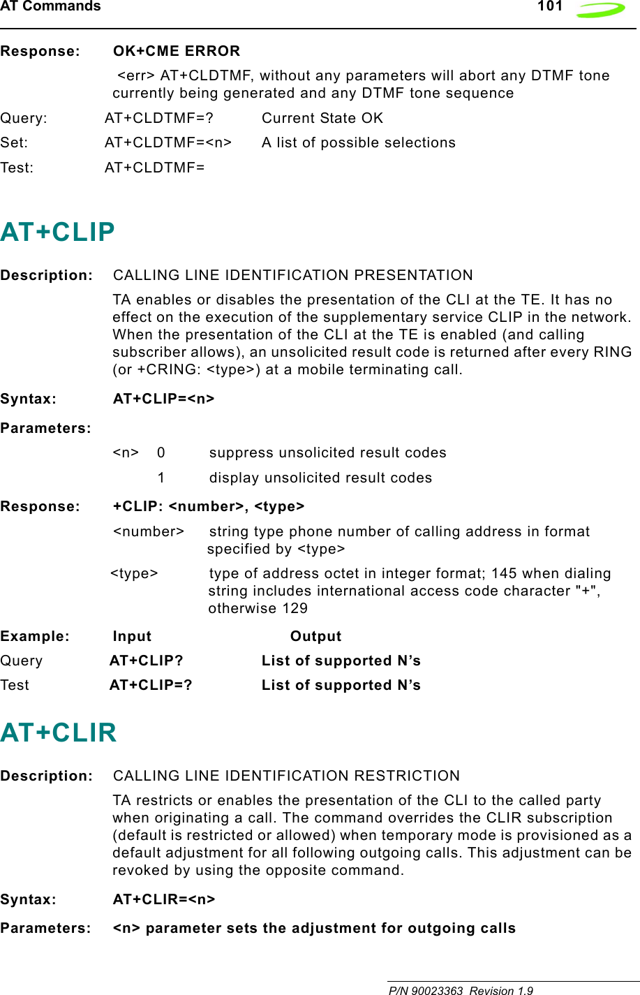
![AT Commands 99 P/N 90023363 Revision 1.9AT+CLCKDescription: FACILITY LOCK This command is used to lock, unlock or interrogate an ME or a network facility. A password is normally needed to perform such actions. When querying the status of a network service (<mode>=2) the response line for ‘not active’ case (<status>=0) should be returned only if service is not active for any <class>.Syntax: AT+CLCK = <fac>, <mode>[,<passwd>[,<class>]]Parameters:<fac> “PS” PH-SIM (lock PHone to SIM card) (ME asks password when other than current SIM card inserted; ME may remember certain amount of previously used cards thus not requiring password when they are inserted).“SC” SIM (lock SIM card) (SIM asks password in ME power-up and when this lock command issued).“AO” BAOC (Barr All Outgoing Calls) (refer GSM02.88[6] clause 1)“O” BOIC (Barr Outgoing International Calls) (refer GSM02.88[6] clause 1)“OX” BOIC-exHC (Barr Outgoing International Calls except to Home Country) (refer GSM02.88[6] clause 1)“AI” BAIC (Barr All Incoming Calls) (refer GSM02.88[6] clause 2)“IR” BIC-Roam (Barr Incoming Calls when Roaming outside the home country) (refer GSM02.88 [6] clause 2)“AB” All Barring services (refer GSM02.30[19]) (applicable only for <mode>=0)“AG” All out Going barring services (refer GSM02.30[19]) (applicable only for <mode>=0)“AC” All in Coming barring services (refer GSM02.30[19]) (applicable only for <mode>=0)“PN” Network Personalization (refer GSM 02.22[33])"PU” network sUbset Personalization (refer GSM 02.22[33])"PP” service Provider Personalization (refer GSM 02.22[33])"PC” Corporate Personalization (refer GSM 02.22[33])<mode> 0 unlock1lock](https://usermanual.wiki/Novatel-Wireless/NRM-EG301.Revised-Users-manual/User-Guide-315684-Page-107.png)
![100 AT Commands Revision 1.9 P/N 900233632 query status<passwd> password<class> 1 voice2data4fax7 all classes (default)<status> 0 off1onResponse: If <mode><>2 and command is successful OKIf <mode>=2 and command is successful +CLCK: <status>[,<class1>[<cr><LF> +CLCK: <status>, class2....]] OKIf error is related to ME functionality: +CME ERROR: <err>Example: Input OutputQuery AT+CLCK? 129 OKTe s t AT+CLCK=? LIST OF SUPPORTED (<fac>s) OKAT+CLDTMF Description: GENERATE LOCAL DTMF TONESyntax: AT+CLDTMF=<n>,<dtmf-string>Parameters:<n> Duration of all DTMF tones in <dtmf-string> in 1/10 seconds.<dtmf-string>As a max length of 20 characters of form <dtmf>, must be entered between double quotes (“ “) and consists of combinations of the following separated by commas.<dtmf> A single ASCII characters in the set 0-9,#,*,A-D. This is interpreted as a sequence of DTMF tones whose duration is set by <n>.](https://usermanual.wiki/Novatel-Wireless/NRM-EG301.Revised-Users-manual/User-Guide-315684-Page-108.png)
![AT Commands 103 P/N 90023363 Revision 1.9Test +CLVL: (list of supported <level>s)+CME ERROR: <err>AT+CMEEDescription: REPORT MOBILE EQUIPMENT ERRORModem disables or enables the use of result code +CME ERROR: <err> as an indication of an error relating to the functionality of the mobile equipment.Syntax: AT+CMEE=<n>Parameters:<n> 0 disable result code1 enable result code and use numeric values2 enable result code and use verbose valueResponse: <n> OKExample: Input OutputQuery AT+CMEE? <n> OKTes t AT+CMEE=? List of supported <n>s OKAT+CMGDDescription: DELETE SMS MESSAGEDeletes message from preferred message storage location.Syntax: AT+CMGD=<index>Parameters:<index> integer type; value in the range of location numbers supported by the associated memoryResponse: OKExample: Input OutputTes t AT+CMGD=? OK AT+CMGFDescription: SMS MESSAGE FORMATSets parameter to dictate which input and output format of messages to use.Syntax: AT+CMGF = [<mode>]](https://usermanual.wiki/Novatel-Wireless/NRM-EG301.Revised-Users-manual/User-Guide-315684-Page-111.png)
![104 AT Commands Revision 1.9 P/N 90023363Parameters:<mode> 0 PDU mode1 text modeResponse: OKExample: Input OutputQuery AT+CMGF? +CMGF: <mode> OK Te s t AT+CMGF=? +CMGF: list of supported <mode>s OK AT+CMGLDescription: LIST SMS MESSAGESReturns messages with status value <stat> from message storage <mem1> to the TE. If status of the message is 'received unread', status in the storage changes to 'received read'.Syntax: AT+CMGL [=<stat>]Parameters:<stat> Text Mode “REC UNREAD” Received unread message (default)“REC READ” Received read messages."STO UNSENT" Stored unsent messages"STO SENT" Stored sent messages"ALL" All messagesPDU Mode 0 Received unread messages (default)1 Received read messages2 Stored unsent messages3 Stored sent messages4 All messagesResponse:1. If text mode (+CMGF=1) and command successful: for SMS-SUBMITs and/or SMS-DELIVERs:+CMGL: <index>,<stat>,<oa/da>,[<alpha>],[<scts>][,<tooa/toda>,<length>]<cr><LF><data>[<cr><LF>+CMGL: <index>,<stat>,<da/oa>,[<alpha>],[<scts>][,<tooa/toda>,<length>]<cr><LF><data>[...]] OK2. If PDU mode (+CMGF=0) and command successful: +CMGL: <index>,<stat>,[<alpha>],<length><cr><LF><pdu>[<cr><LF>+CMGL: <index>,<stat>,[alpha],<length><cr><LF><pdu>[...]] OK3. If error is related to ME functionality: +CMS ERROR: <err>](https://usermanual.wiki/Novatel-Wireless/NRM-EG301.Revised-Users-manual/User-Guide-315684-Page-112.png)
![106 AT Commands Revision 1.9 P/N 90023363integer value 42 is presented to TE as two characters 2A (IRA 50 and 65)). In the case of CBS: GSM 03.41 TPDU in hexadecimal format.<scts> GSM 03.40 TP-Service-Center-Time-Stamp in time-string format (refer <dt>)<toda> GSM 04.11 TP-Destination-Address Type-of-Address octet in integer format (when first character of <da> is + (IRA 43) default is 145, otherwise default is 129)<tooa> GSM 04.11 TP-Originating-Address Type-of-Address octet in integer format (default refer<toda>)Example: Input OutputTe s t AT+CMGL=? +CMGF: list of supported <stats>s OKAT+CMGRDescription: READ SMS MESSAGEReturns SMS message with location value <index> from message storage <mem1> to the TE. If status of the message is 'received unread', status in the storage changes to 'received read'.Syntax: AT+CMGR=<index>Parameters:<index> integer type; value in the range of location numbers supported by the associated memory.Response:1.If text mode (+CMGF=1) and command successful: for SMS-DELIVER:+CMGR: <stat>,<oa>,[<alpha>],<scts> [,<tooa>,<fo>,<pid>,<dcs>,<sca>,<tosca>,<length>]<cr><LF><data>for SMS-SUBMIT:+CMGR: <stat>,<da>,[<alpha>] [,<toda>,<fo>,<pid>,<dcs>,[<vp>],<sca>,<tosca>,<length>]<cr><LF><data>2. If PDU mode (+CMGF=0) and command successful:+CMGR: <stat>,[<alpha>],<length><cr><LF><pdu> OK](https://usermanual.wiki/Novatel-Wireless/NRM-EG301.Revised-Users-manual/User-Guide-315684-Page-114.png)
![108 AT Commands Revision 1.9 P/N 90023363<oa> GSM 03.40 TP-Originating-Address, Address-Value field in string format; BCD numbers (or GSM default alphabet characters) are converted to characters; type of address given by <tooa>.<pdu> In the case of SMS: GSM 04.11 SC address followed by GSM 03.40 TPDU in hexadecimal format: ME/TA converts each octet of TP data unit into two IRA character long hexadecimal number (e.g. octet with integer value 42 is presented to TE as two characters 2A (IRA 50 and 65). In the case of CBS: GSM 03.41 TPDU in hexadecimal format.<sca> GSM 04.11 RP SC address Address Value field in string format; BCD numbers (or GSM default alphabet characters) are converted to characters; type of address given by <tosca>.<stat> 0 “REC UNREAD” Received unread messages1 “REC READ” Received read messages2 “STO UNSENT” Stored unsent messages3 “STO SENT” Stored sent messages4 “ALL” All messages<toda> GSM 04.11 TP-Destination-Address Type-of-Address octet in integer format (when first character of <da> is + (IRA 43) default is 145, otherwise default is 129)<tooa> GSM 04.11 TP-Originating-Address Type-of-Address octet in integer format (default refer<toda>).<tosca> GSM 04.11 RP SC address Type-of-Address octet in integer format (default refer <toda>).<vp> depending on SMS-SUBMIT <fo> setting: GSM 03.40 TP-Validity-Period either in integer format (default 167) or in time-string format (refer <dt>)Example: Input OutputTe s t AT+CMGR=? +CMGR: list of supported <index>s OKAT+CMGWDescription: WRITE SMS MESSAGE TO MEMORYTransmits SMS message from terminal to memory storage. Memory location of the stored message is returned. By default message status will be set to 'stored unsent', but parameter allows other status values to be given.Syntax:TEXT MODE: AT+CMGS=[<oa/da>[,<tooa/toda>]]<cr> MESSAGE TEXT <ctrlZ> PDU MODE: AT+CMGW==<length><cr> PDU IS GIVEN <ctrlZ>SENDS MESSAGE <ctrlZ>](https://usermanual.wiki/Novatel-Wireless/NRM-EG301.Revised-Users-manual/User-Guide-315684-Page-116.png)
![AT Commands 109 P/N 90023363 Revision 1.9EXITS WITHOUT SENDING <esc>Parameters:<oa> GSM 03.40 TP-Originating-Address, Address-Value field in string format; BCD numbers (or GSM default alphabet characters) are converted to characters; type of address given by <tooa><da> GSM 03.40 TP-Destination-Address, Address-Value field in string format; BCD numbers (or GSM default alphabet characters) are converted to characters; type of address given by <toda><tooa> GSM 04.11 TP-Originating-Address Type-of-Address octet in integer format (default refer <toda>).<toda> GSM 04.11 TP-Destination-Address Type-of-Address octet in integer format (when first character of <da> is + (IRA 43) default is 145, otherwise default is 129)<length> Integer type value indicating in the text mode (+CMGF=1) the length of the message body <data> (or <cdata>) in characters; or in PDU mode (+CMGF=0), the length of the actual TP data unit in octets (i.e. the RP layer SMSC address octets are not counted in the length)<pdu> In the case of SMS: GSM 04.11 SC address followed by GSM 03.40 TPDU in hexadecimal format: ME/TA converts each octet of TP data unit into two IRA character long hexadecimal number (e.g. octet with integer value 42 is presented to TE as two characters 2A (IRA 50 and 65)). In the case of CBS: GSM 03.41 TPDU in hexadecimal format.<index> Index of message in selected storage <mem2>Response: If writing is successful: +CMGW: <index> OKIf error is related to ME functionality: +CMS ERROR: <err>Example: Input OutputTes t AT+CMGW=? OKAT+CMSSDescription: SEND STORED SMS MESSAGESends message with location value <index> from message storage <mem2> to the network (SMS-SUBMIT). If new recipient address <da> is given, it shall be used instead of the one stored with the message. Reference value <mr> is returned to the TE on successful message delivery. Values can be used to identify message upon unsolicited delivery status report result code.Syntax: AT+CMSS=<index>[,<da>[,<toda>]]Parameters:](https://usermanual.wiki/Novatel-Wireless/NRM-EG301.Revised-Users-manual/User-Guide-315684-Page-117.png)
![AT Commands 111 P/N 90023363 Revision 1.9Query +CMUX: <mode>+CME ERROR: <err>Test +CMUX: (list of supported <mode>s)AT+CNMIDescription: SMS MESSAGE ARRIVAL INDICATIONSelects the procedure for receiving of new messages from the network. Indicates to the TE when TE is active, e.g. DTR signal is ON. If TE is inactive (e.g. DTR signal is OFF), message receiving should be done as specified in GSM 03.38.Syntax: AT+CNMI = [<mode>[,<mt>[,<bm>[,<ds>[,<bfr>]]]]]Parameters:<mode> 0 Buffer unsolicited result codes in the TA. If TA result code buffer is full, indications can be buffered in some other place or the oldest indications may be discarded and replaced with the new received indications.1 Discard indication and reject new received message unsolicited result codes when TA-TE link is reserved (e.g. in on-line data mode). Otherwise forward them directly to the TE.2 Buffer unsolicited result codes in the TA when TA-TE link is reserved (e.g. in on-line data mode) and flush them to the TE after reservation. Otherwise forward them directly to the TE.3 Forward unsolicited result codes directly to the TE. TA-TE link specific in band technique used to embed result codes and data when TA is in on-line data mode.<mt> The rules for storing received SMs depend on its data coding scheme (refer GSM 03.38 [2], preferred memory storage (+CPMS) setting and this value:0 No SMS-DELIVER indications are routed to the TE.1 If SMS-DELIVER is stored into ME/TA, indication of the memory location is routed to the TE using unsolicited result code: +CMTI: <mem>,<index>2 SMS-DELIVERs (except class 2) are routed directly to the TE using unsolicited result code: +CMT: [<alpha>],<length><cr><LF><pdu> (PDU mode enabled) or +CMT: <oa>, [<alpha>],<scts> [,<tooa>,<fo>,<pid>,<dcs>,<sca>,<tosca>,<length>]<cr><LF><data> (text mode enabled; about](https://usermanual.wiki/Novatel-Wireless/NRM-EG301.Revised-Users-manual/User-Guide-315684-Page-119.png)
![112 AT Commands Revision 1.9 P/N 90023363parameters in italics, refer command Show Text Mode Parameters +CSDH). Class 2 messages result in indication as defined in <mt>=1.3 Class 3 SMS-DELIVERs are routed directly to TE using unsolicited result codes defined in <mt>=2. Messages of other classes result in indication as defined in <mt>=1.<bm> The rules for storing received CBMs depend on its data coding scheme (refer GSM 03.38 [2]), the setting of Select CBM Types (+CSCB) and the following values:0 No CBM indications are routed to the TE.2 New CBMs are routed directly to the TE using unsolicited result code: +CBM: <length><cr><LF><pdu> (PDU mode enabled) or +CBM: <sn>,<mid>,<dcs>,<page>,<pages><cr><LF><data> (text mode enabled).<ds> 0 No SMS-STATUS-REPORTs are routed to the TE.1 SMS-STATUS-REPORTs are routed to the TE using unsolicited result code: +CDS: <length><cr><LF><pdu> (PDU mode enabled) or +CDS: <fo>,<mr>,[<ra>],[<tora>],<scts>,<dt>,<st> (text mode enabled)<bfr> 0 TA buffer of unsolicited result codes defined within this command is flushed to the TE when <mode> 1...3 is entered (OK response shall be given before flushing the codes).1 TA buffer of unsolicited result codes defined within this command is cleared when <mode> 1...3 is entered.Response: OKUnsolicited Response:+CMTI: <mem>,<index> Indication that new message has been received+CMT: ,<length><cr><LF><pdu> Short message is output directly+CBM: <length><cr><LF><pdu> Cell broadcast message is output directlyExample: Input OutputTe s t AT+CNMI=? OKAT+CNUMDescription: SUBSCRIBER NUMBER](https://usermanual.wiki/Novatel-Wireless/NRM-EG301.Revised-Users-manual/User-Guide-315684-Page-120.png)
![AT Commands 113 P/N 90023363 Revision 1.9This is a query command is used to retrieve the current subscriber number and associated information.Syntax: AT+CNUM<alphax> optional alphanumeric string associated with <numberx> used character set should be the one selected with commandSelect TE Character Set +CSCS<numberx> string type phone number of format specified by <typex><typex> type of address octet in integer format (refer GSM 04.08 [8]subclause 10.5.4.7)<speed> as defined by the +CBST command<service> service related to the phone number0 asynchronous modem1 synchronous modem2 PAD Access (asynchronous)3 Packet Access (synchronous)4Voice5Fax<itc> information transfer capability 03.1 kHzAT+COLPDescription: CONNECTED LINE IDENTIFICATION PRESENTATIONTA enables or disables the presentation of the COL(Connected Line) at the TE for a mobile originated call. It has no effect on the execution of the supplementary service COLR in the network. Intermediate result code is returned from TA to TE before any +CR or V.25ter responses.Syntax: AT+COLP=[<n>]](https://usermanual.wiki/Novatel-Wireless/NRM-EG301.Revised-Users-manual/User-Guide-315684-Page-121.png)
![114 AT Commands Revision 1.9 P/N 90023363Parameters:<n> 0 disable1 enable<m> 0 COLP not provisioned1 COLP provisioned2 Unknown (e.i no network)Response: +COLP:,NUMBER>,<TYPE>[,SUBADDR>,SATYPE>[,<ALPHA>]]<number> string type phone number of format specified by <type><type> type of address octet in integer format; 145 when dialing string includes international access code character "+", otherwise 1<subaddr> string type sub address of format specified by <satype><satype> type of sub address octet in integer format (refer GSM 04.08 [8] sub clause 10.5.4.8)<alpha> optional string type alphanumeric representation of <number> corresponding to the entry found in phone bookExample: Input ResponseQuery AT+COLP? +COLP:<n>,<m> OKTe s t AT+COLP=? +COLP:(List of supported <n>s) OKAT+COPNDescription: READ OPERATOR NAMEExecute command returns the list of operator names from the ME. Each operator code that has an alphanumeric equivalent in the ME memory shall be returned. Syntax: AT+COPNParameters: <numericn>: string type;operator in numeric format<alphan>: string type;operator in long alphanumeric formatResponse: +COPN: <numeric1>, <alpha>[<CR><LF>+COPN: <numeric2>, <alpha2>[...]]](https://usermanual.wiki/Novatel-Wireless/NRM-EG301.Revised-Users-manual/User-Guide-315684-Page-122.png)
![AT Commands 115 P/N 90023363 Revision 1.9AT+COPSDescription: OPERATOR SELECTIONSET forces an attempt to select and register the GSM network operator. If the selected operator is not available, no other operator shall be selected (except <mode>=4). The selected operator name format shall apply to further read commands (+COPS?).QUERY returns a list of quadruplets, each representing an operator present in the network. The formats may be unavailable, in this case the field should be empty. The list of operators shall be in order: home network, networks referenced in SIM, and other networks.Syntax: AT+COPS = <mode>[, <format>[, <oper>]]Parameters:<oper> operator in format as per <mode><mode> 0 automatic mode; <oper> field is ignored1 manual operator selection; <oper> field shall be present2 manual de-register from network3 set only <format> (for read command +COPS?) – not shown in Read command response4 manual/automatic selected; if manual selection fails, automatic mode (<mode>=0) is entered<format> 0 long format alphanumeric <oper>;can be up to 16 characters long1 short format alphanumeric <oper>2 numeric <oper>; GSM Location Area Identification numberResponse: +COPS: (<stat>, <oper>, <oper>)s [,,(<mode>s),(<format>s)] <stat> 0 unknown1 operator available2 operator current3 operator forbidden<oper> operator in format as per <mode><mode> 0 automatic mode; <oper> field is ignored1 manual operator selection; <oper> field2 manual de-register from network3 set only <format> (for read command +COPS?) – not shown in Read command response](https://usermanual.wiki/Novatel-Wireless/NRM-EG301.Revised-Users-manual/User-Guide-315684-Page-123.png)
![116 AT Commands Revision 1.9 P/N 900233634 manual/automatic selected; if manual selection fails, automatic mode (<mode>=0) is entered<format> 0 long format alphanumeric <oper>;can be up to 16 characters long1 short format alphanumeric <oper>2 numeric <oper>; GSM Location Area Identification numberExample: Input ResponseQuery AT+COPS? List of supported <stat>, <oper>,<mode>,<format> OKTe s t AT+COPS=? +COPS: <mode>[,<format>[,<oper>]] OKAT+CPASDescription: MOBILE EQUIPMENT ACTIVITY STATUSReturns the current equipment activity status.Syntax: AT+CPASParameters: NoneResponse: +CPAS: <pas> OK0 ready2 unknown (ME is not guaranteed to respond to instructions)3 incoming call (ringing)4 call in progress or call holdExample: Input ResponseTe s t AT+CPAS=? 4 OKAT+CPBFDescription: PHONE BOOK, FIND ENTRIESReturns phone book entries (from the current phone book memory storage selected with +CPBS) containing alphanumeric string <findtext>.Syntax: AT+CPBF=<findtext>Parameters: Findtex - An ASCII string which may or may not be contained in the phone book.Response: [+CPBF: <index1>,<number>,<type>,<text>[[...]<cr><LF>+CBPF: <index2>,<number>,<type>,<text>] OK]<index1><index1> integer type values in the range of location numbers of phone book memory](https://usermanual.wiki/Novatel-Wireless/NRM-EG301.Revised-Users-manual/User-Guide-315684-Page-124.png)
![AT Commands 117 P/N 90023363 Revision 1.9<index2> integer type values in the range of location numbers of phone book memory<number> string type phone number of format <type><type> type of address octet in integer format ; 145 when dialling string includes international access code character “+“, otherwise 129<findtext> string type field of maximum length <tlength><text> string type field of maximum length <tlength><nlength> integer type value indicating the maximum length of field <number><tlength> integer type value indicating the maximum length of field <text>Example: Input ResponseQuery AT+CPBF=? OKTes t +CPBF: [<nlength)],[<tlength>] OKAT+CPBRDescription: PHONE BOOK READReturns phone book entries in location number range <index1>... <index2> from the current phone book memory storage selected with +CPBS. If <index2> is left out, only location <index1> is returned.Syntax: AT+CPBR = <index1>[, <index2>]Parameters:<index1> read as of this location number<index2> read to this location number<number> phone number<type> type of number<text> text for phone numberResponse: +CPBR: <index1>, <number>, <type>, <text>[<cr><LF>+CPBR: .....+CPBR: <index2>, <number>, <type>, <text>] OKExample: Input ResponseTes t AT+CPBR=? +CPBR: (<index>s), <nlength>, <tlength> OK](https://usermanual.wiki/Novatel-Wireless/NRM-EG301.Revised-Users-manual/User-Guide-315684-Page-125.png)
![118 AT Commands Revision 1.9 P/N 90023363AT+CPBSDescription: PHONE BOOK STORAGE SELECTIONSSelects current phone book memory storage, which is used by other phone book commands.Syntax: AT+CPBS=<storage>Parameters:<storage> DC Modem dialed calls list (+CPBW may not be applicable for this storage)FD SIM fix dialing-phone bookLD SIM last-dialing-phone bookON SIM (or ME) own numbers (MSISDNs) listSM SIM phone bookExample: Input ResponseQuery AT+CPBS? <storage> OK Te s t AT+CPBS=? list of supported <storage>s OKAT+CPBWDescription: PHONE BOOK WRITE ENTRYThis command writes phone book entry in location number <index> in the current phone book memory storage selected with +CPBS. Entry fields written are phone number <number> (in the format <type>) and text <text> associated with the number. If those fields are omitted, phone book entry is deleted. If <index> is limited, but <number> is given, entry is written to the first free location in the phone book.Syntax: AT+CPBW = [<index>], [<number>, [<type>, [<text>]]]Parameters:<nlength> max. length of phone number<tlength> max. length of text for number<index> location number<number> phone number<type> type of number; e.g. 145 when dialing string includes international access code character "+", otherwise 129<text> text for phone numberResponse: +CPBW: (<index>s),<nlength>,( <typ>s),<tlength> OK](https://usermanual.wiki/Novatel-Wireless/NRM-EG301.Revised-Users-manual/User-Guide-315684-Page-126.png)
![AT Commands 119 P/N 90023363 Revision 1.9Example: Input ResponseTes t AT+CPBW+? (<index>s),<nlength>,( <typ>s),<tlength> OK The following characters in <text> must be entered via the escape sequence:GSM Char Seq. Seq.(hex) Note\ \5C 5C 35 43 (backslash)“ \22 5C 32 32 (string delimiter)BSP \08 5C 30 38 (backspace)NULL \00 5C 30 30 (GSM null)‘0’ (GSM null) may cause problems for application layer software when reading string lengths.AT+CPINDescription: ENTER PINStores a password which is necessary before it can be operated (SIM PIN, SIM PUK, PH?SIM PIN, etc.). If the PIN is to be entered twice, the TA shall automatically repeat the PIN. If no PIN request is pending, no action is taken and an error message, +CME ERROR, is returned to TE. If the PIN required is SIM PUK or SIM PUK2, the second pin is required. This second pin, <newpin>, is used to replace the old pin in the SIM.Syntax: AT+CPIN=<pin>[, <new pin>]Parameters:<pin> string type; password <new pin> string type; If the PIN required is SIM PUK or SIM PUK2: new passwordResponse: +CPIN: <code> OKREADY no further entry neededSIM PIN ME is waiting for SIM PINSIM PUK ME is waiting for SIM PUKPH_SIM PIN ME is waiting for phone to SIM card (antitheft)PH_SIM PUK ME is waiting for SIM PUK (antitheft)SIM PIN2 PIN2, e.g. for editing the FDN book possible only if preceding command was acknowledged with +CME ERROR:17](https://usermanual.wiki/Novatel-Wireless/NRM-EG301.Revised-Users-manual/User-Guide-315684-Page-127.png)
![120 AT Commands Revision 1.9 P/N 90023363SIM PUK2 possible only if preceding command was acknowledged with error +CME ERROR:18.Example: Input ResponseQuery AT+CPIN? <code> OK Te s t AT+CPIN=? OKAT+CPMSDescription: PREFERRED SMS MESSAGE STORAGESelects memory storages <mem1>, <mem2> and <mem3> to be used for reading, writing.Syntax: AT+CPMS = <mem1>[,<mem2>[,<mem3>]]Parameters:<mem1> Messages to be read and deleted from this memory storage "SM" SIM message storage<mem2> Messages will be written and sent to this memory storage "SM" SIM message storage<mem3> Received messages will be placed in this memory storage if routing to PC is not set "+CNMI") "SM" SIM message storage <usedx> Number of messages currently in <memx><totalx> Number of messages storable in <memx>Response: +CPMS: <used1>,<total1>,<used2>,<total2>,<used3>,<total3> OKExample: Input ResponseTest: AT+CPMS=? list of supported <mem1>s OKlist of supported <mem2>s OK list of supported <mem3>s OKQuery: AT+CPMS=?CPMS:<mem1>,<used1>,<total1>,<mem2>,<used2>,<total2>,<mem3>,<used3>,<total3>OKAT+CPOLDescription: PREFERRED OPERATOR LISTThis command is used to edit the SIM preferred list of networks. Execute command writes an entry in the SIM list of preferred operators. If <index> is given but <oper> is left out, entry is deleted. If <oper> is given but <index> is left out, <oper> is put in the next free location. If only <format> is given, the format of the <oper> in the read command is changed.](https://usermanual.wiki/Novatel-Wireless/NRM-EG301.Revised-Users-manual/User-Guide-315684-Page-128.png)
![AT Commands 121 P/N 90023363 Revision 1.9Syntax: AT+CPOL=[<index>][,<format>[,<oper>]]Parameters:<index> integer type: order number of operator in SIM preferred operator list <format> 0 long format alphanumeric <oper>1 short format alphanumeric <oper>2 numeric <oper><oper>string type: <format> indicates whether alphanumeric or numeric format used (see +COPS command)Response:Query AT+CPOL <index1>,<format>,<oper1>[<CR><LF>+CPOL: <index2>,<format>,<oper2>[…]]+CME ERROR: <err>Tes t AT+CPOL? (list of supported <index>s),(list of supported <format>s)AT+CPUCDescription: PRICE PER UNIT AND CURRENCY TABLE SETTINGThis command sets the conversion from minutes of use to the local currency cost.Syntax: AT+CPUC=<currency>,<ppu>[,<passwd>]Parameters:<currency> string type; three-character currency code (e.g. "GBP", "DEM"); character set as specified by command Select TE Character Set +CSCS<currency> string type; price per unit; dot is used as a decimal separator (e.g. "2.66")<passwd> string type; SIM PIN2Response: OKQuery AT+CPUC <currency>,<ppu>+CME ERROR: <err>Tes t AT+CPUC? <err>AT+CPWDDescription: PASSWORD CHANGESets a new password for the facility lock function.Syntax: AT+CPWD = <fac>, [<oldpwd>], <newpwd>Parameters:<fac> SC SIM (lock SIM card) (SIM asks password in ME power-up and when this lock command issued)](https://usermanual.wiki/Novatel-Wireless/NRM-EG301.Revised-Users-manual/User-Guide-315684-Page-129.png)
![122 AT Commands Revision 1.9 P/N 90023363AO BAOC (Barr All Outgoing Calls) (refer GSM02.88[6] clause 1)OI BOIC (Barr Outgoing International Calls) (refer GSM02.88[6] clause 1)OX BOIC-exHC (Barr Outgoing International Calls except to Home Country) (refer GSM02.88[6] clause 1)AI BAIC (Barr All Incoming Calls) (refer GSM02.88[6] clause 2)IR BIC-Roam (Barr Incoming Calls when Roaming outside the home country) (refer GSM02.88 [6] clause 2)AB All Barring services (refer GSM02.30[19]) (applicable only for <mode>=0)AG All outGoing barring services (refer GSM02.30[19]) (applicable only for <mode>=0)AC All inComing barring services (refer GSM02.30[19]) (applicable only for <mode>=0)P2 SIM PIN2<oldpwd> password specified for the facility from the user interface or with command. If an old password has not yet been set, <oldpwd> is not to enter.<newpwd> new password<pwdlength> integer max. length of passwordResponse: +CPWD: (<fac>, <pwdlength>)s OKExample: Input ResponseTe s t AT+CPWD=? list of supported <fac>s,<pwdlength>s OK](https://usermanual.wiki/Novatel-Wireless/NRM-EG301.Revised-Users-manual/User-Guide-315684-Page-130.png)
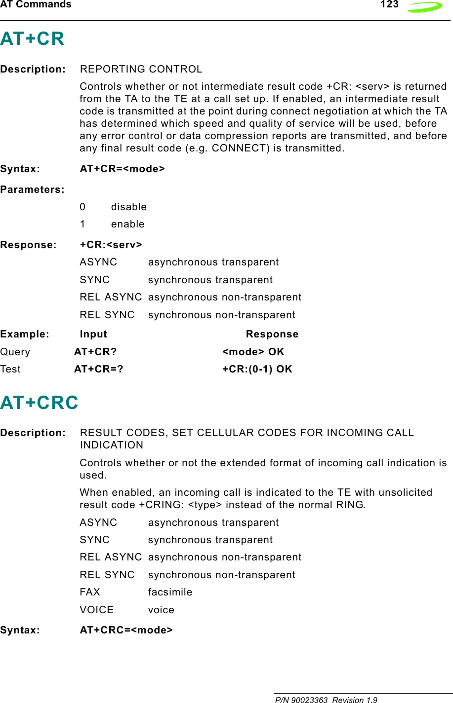
![124 AT Commands Revision 1.9 P/N 90023363Parameters:<mode> 0 disable extended format1 enable extended formatResponse: OKExample: Input ResponseQuery AT+CRC? 129 OK Te s t AT+CRC=? 129,145 OKAT+CREGDescription: REGISTRATION INDICATIONReturns the status of result code presentation and an integer <stat> which shows whether the network has currently indicated the registration of the ME. Location information elements <lac> and <ci> are returned only when <n>=2 and ME is registered in the network.Syntax: AT+CREG=[<n>]Parameters:<n> 0 disable network registration unsolicited result code1 enable network registration unsolicited result code +CREG: <stat><stat> 0 not registered, ME is not currently searching a new operator to register to1 registered, home network2 not registered, but ME is currently searching a new operator to register to3 registration denied4 unknown5 registered, roamingResponse: +CREG: <n>,<stat> OKExample: Input ResponseQuery AT+CREG? <n>,<stat> OK Te s t AT+CREG=? list of supported <n>s OKAT+CRESDescription: RESTORE MESSAGE SERVICE SETTINGSThis command restores SMS settings for +CMGF, +CNMI, +CSDH from non-volatile memory to active memory.](https://usermanual.wiki/Novatel-Wireless/NRM-EG301.Revised-Users-manual/User-Guide-315684-Page-132.png)
![AT Commands 125 P/N 90023363 Revision 1.9Syntax: AT+CRES[=<profile>]<CR>Parameters:<profile> manufacturer specific profile number where settings are to be storedResponse:Tes t AT+CRESAS=?<CR> list of supported <profile>s OKAT+CRLPDescription: RADIO LINK PROTOCOL SELECTSets radio link protocol (RLP) parameters used when non-transparent data calls are setup, returns values supported. RLP versions 0 and 1 share the same parameter set. TA returns only one line for this set (where <verx> is not present).Syntax: AT+CRLP=[<iws>[,<mws>[,<T1>[,<N2>[,<ver>[,<T4>]]]]]]Parameters:<iws> 0 6I 255 Interworking window size (IWF to MS)<mws> 0 6I 255 Mobile window cesiums to IWF)<T1> 0 48 255 acknowledgment timer T1 in 10 ms units)<N2> 0 6 255 retransmission attempts N2<verx> 0-1 RLP version number in integer format; when version indication is not present it shall equal 0. Versions 0 and 1 share the same parameter set.<T4> 0-3-255 Re-sequencing period in integer format, in units of 10 ms. This is NOT used for RLP versions 0 and 1.Response: +CRLP: <iws>,<mws>,<T1>,<N2>,<ver1>,<T4>Example: Input ResponseQuery AT+CRLP? returns current settings for RLP version. RLP versions 0 and 1 share the same parameter set. TA returns only one line for this set (where <verx> is not present) Tes t AT+CRLP=? list of possible settings. OKAT+CRSLDescription: RINGER SOUND LEVELThis command sets the ring volume for a phone or voice device.](https://usermanual.wiki/Novatel-Wireless/NRM-EG301.Revised-Users-manual/User-Guide-315684-Page-133.png)
![126 AT Commands Revision 1.9 P/N 90023363Syntax: AT+CRSL=<level>Parameters:<level> integer type value with manufacturer specific range (smallest value represents the lowest sound level)Response:Query +CRSL: <level>+CME ERROR: <err>Te s t +CRSL: (list of supported <level>s)+CME ERROR: <err>AT+CSASDescription: RESTORE MESSAGE SERVICE SETTINGSRestores SMS settings for +CMGF, +CNMI, +CSDH from non-volatile memory to active memory.Syntax: AT+CSAS[=<profile>]Parameters: <profile>manufacturer specific profile number where settings are to be storedResponse: OKExample: Input ResponseTe s t AT+CSAS=? list of supported <profile>s OKAT+CSCADescription: SMS SERVICE CENTER ADDRESSUpdates the SMSC address, through which mobile originated SMs are transmitted. In text mode, setting is used by send and write commands. In PDU mode, setting is used by the same commands, but only when the length of the SMSC address coded into <pdu> parameter equals zero. This command writes the parameters in the NON-VOLATILE memory.Syntax: AT+CSCA = <sca>[,<tosca>]Parameters:<sca> GSM 04.11 RP SC address Address-Value field in string format; BCD numbers (or GSM default alphabet characters) are converted to characters; type of address given by <tosca>](https://usermanual.wiki/Novatel-Wireless/NRM-EG301.Revised-Users-manual/User-Guide-315684-Page-134.png)
![AT Commands 127 P/N 90023363 Revision 1.9<tosca> Service center address format GSM 04.11 RP SC address Type-of-Address octet in integer format default refer <toda>)Response: OKExample: Input ResponseQuery AT+CSCA? +CSCA:<sca>,<tosca> OKTes t AT+CSCA=? OKAT+CSCBDescription: CELL BROADCAST MESSAGE SELECTIONSelects which types of cell broadcast messages that are to be received by the device. The command writes the parameters in NON-VOLATILE memory.Syntax: AT+CSCB=[<mode>[,mids>[,<dcss>]]]Parameters:<mode> 0 message types specified in <mids> and <dcss> are accepted1 message types specified in <mids> and <dcss> are not accepted<mids> string type; all different possible combinations of CBM message identifiers (refer <mid>) (default is empty string); e.g. "0,1,5,320-478,922". <dcss> string type; all different possible combinations of CBM data coding schemes (refer <dcs>) (default is empty string); e.g. "0-3,5".Response: +CSCB: <mode>,<mids>,<dcss> OKExample: Input ResponseQuery AT+CSCB? +CSCB: <mode>,<mids>,<dcss> OKTes t AT+CSCB=? list of supported <mode>s OKAT+CSCSDescription: SELECT CHARACTER SET](https://usermanual.wiki/Novatel-Wireless/NRM-EG301.Revised-Users-manual/User-Guide-315684-Page-135.png)
![128 AT Commands Revision 1.9 P/N 90023363Sets which character set <chset> is used by the TE. The TA can then convert character strings correctly between the TE and ME character sets.Syntax: AT+CSCS=[<chset>]Parameters: CHSET GSMResponse: OKExample: Input ResponseQuery AT+CSCS? GSM OKTe s t AT+CSCS=? (GSM) OKAT+CSDHDescription: SHOW SMS TEXT MODE PARAMETERSDetermines whether detailed header information is shown in text mode result codes.Syntax: AT+CSDH=<show>Parameters:<show> 0 do not show header values defined in commands +CSCA and +CSMP (<sca>, <tosca>, <fo>, <vp>, <pid> and <dcs>) nor <length>, <toda> or <tooa> in +CMT, +CMGL, +CMGR result codes in text mode1 show the values in result codesResponse: OKExample: Input ResponseQuery AT+CSDH? +CSDH: <show> OKTe s t AT+CSDH=? list of supported <show>s OKAT+CSIMDescription: GENERIC SIM ACCESSThis command used to send a command to the SIM card/module and return the appropriate response.Syntax: AT+CSIM=<length>,<command>Parameters:<length> integer type: length of characters sent to the TE in <command> or <response> (i.e. twice the number of octets in the raw data)<command> hex format: GSM 11.11 SIM command sent from the ME to the SIM](https://usermanual.wiki/Novatel-Wireless/NRM-EG301.Revised-Users-manual/User-Guide-315684-Page-136.png)
![AT Commands 129 P/N 90023363 Revision 1.9Response: +CSIM: <command>,<response>+CME ERROR: <err>hex format: GSM 11.11 response from SIM to <command>AT+CSMINSDescription: SIM REMOVAL/INSERTION ALERTThis command is used to set the method for reporting the transitions of inserting and extracting the SIM from the carrier. It can also be used to determine the current status of the SIM presence.Syntax: AT+CSMINS=<n>Parameters:<n> 0 Disable unsolicited result code1Enable unsolicited result code.Response:<n> 0 Disable unsolicited result code1 Enable unsolicited result codeQuery: AT+CSMINS?<n>, <inserted>Unsolicited result code:+CSMINS: <inserted>Tes t: AT+CSMINS=? <inserted> 0 - SIM change inserted - removed1 - SIM change removed - insertedAT+CSMPDescription: SET SMS TEXT MODE PARAMETERSThis command selects values for additional parameters needed when SM is sent to the network or placed in a storage when text mode is selected (+CMGF=1). It is possible to set the validity period starting from when the SM is received by the SMSC (<vp> is in range 0... 255) or define the absolute time of the validity period termination (<vp> is a string). This command writes the parameters to the NON-VOLATILE memory.Syntax: AT+CSMP=[<fo>[<vp>[,pid>[,<dcs>]]]]Parameters:<fo> depending on the command or result code: first octet of GSM 03.40 SMS-DELIVER, SMS-SUBMIT (default 17), SMS-STATUS-REPORT, or SMS-COMMAND (default 2) in integer format](https://usermanual.wiki/Novatel-Wireless/NRM-EG301.Revised-Users-manual/User-Guide-315684-Page-137.png)
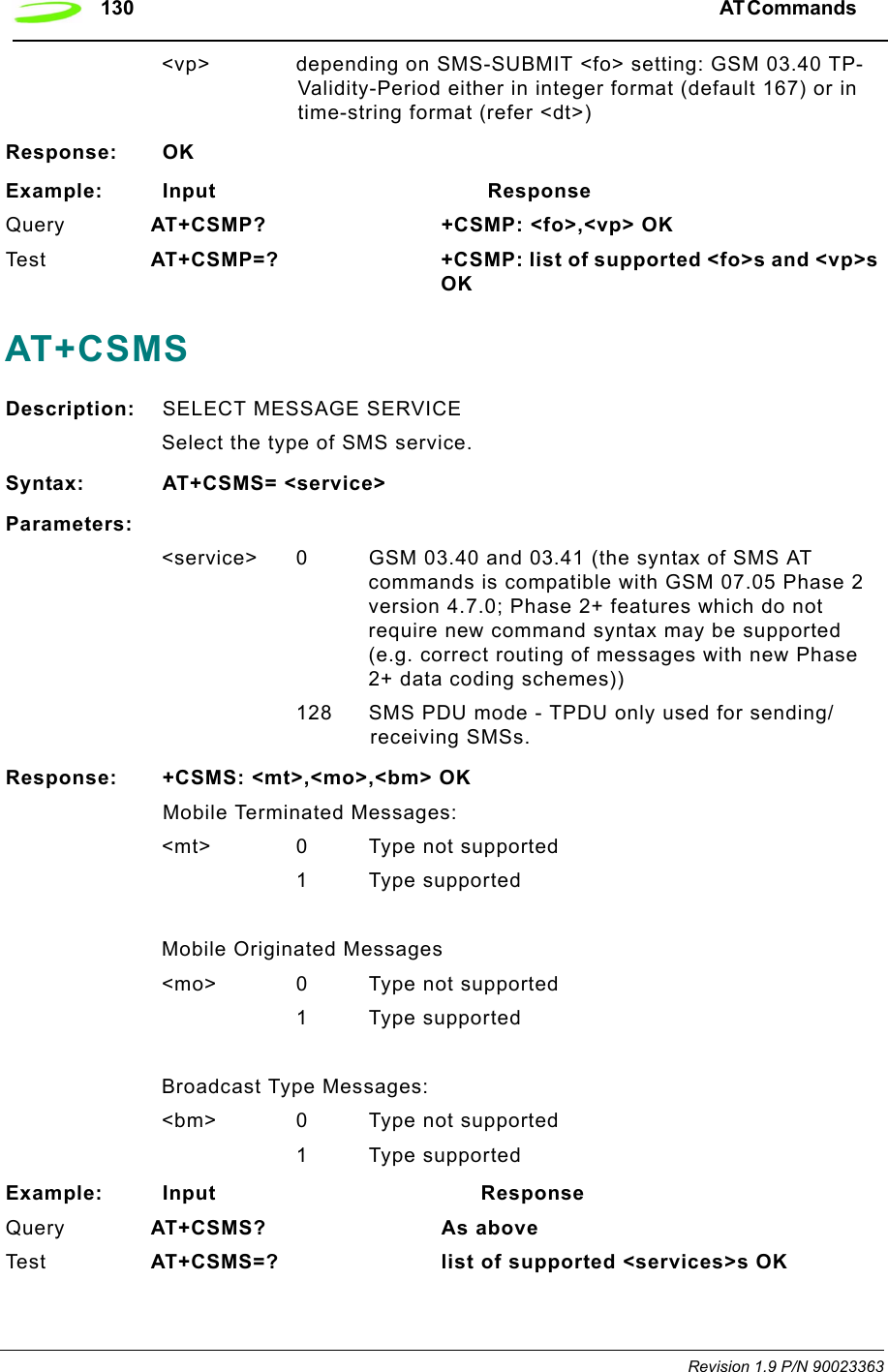
![AT Commands 131 P/N 90023363 Revision 1.9AT+CSQDescription: SIGNAL QUALITY REPORTExecution command returns received signal strength indication and channel bit error rate from the modem. Test command returns values supported by the modem.Syntax: AT+CSQ<cr>Parameters: NoneResponse: +CSQ: <rssi>,<ber>RSSI (in dBm) = (<rssi> X 2) –113 (FOR 0<= <rssi> <=31)RSSI (in dBm) = -51 (FOR 31<= <rssi> <=98)(FOR 99<= <rssi>) rssi is not known or not detectableBER 0...7 as RXQUAL values in the table in GSM 05.08 [20] sub clause 8.2.4BER 99 not known or not detectableExample: Input ResponseTes t AT+CSQ=? list of RSSI and BLER OKAT+CSSNDescription: SUPPLEMENTARY SERVICE NOTIFICATIONAT+CSTADescription: SELECT TYPE OF ADDRESSSelects the type of number for further dialing commands (ATD) according to GSM specifications. The data services software only supports default settings.Syntax: AT+CSTA=[<type>]Parameters:Type 129 Type Unknown145 Type InternationalResponse: OKExample: Input ResponseTes t AT+CSTA? 129 OKQuery AT+CSTA=? (129,145) OK](https://usermanual.wiki/Novatel-Wireless/NRM-EG301.Revised-Users-manual/User-Guide-315684-Page-139.png)
![132 AT Commands Revision 1.9 P/N 90023363AT+CUSDDescription: UNSTRUCTURED SUPPLEMENTARY SERVICE DATAThis command sets the Unstructured response format as well as being used to query the device with regards to the current session status.Syntax: AT+CUSD=[<n>[,<str>[,<dcs>]]]Parameters:<n> 0 disable result code presentation in the TA1 enable result code presentation in the TA2 cancel session<str>string type: USSD string (see GSM 07.07 for use)<dcs> integer type: GSM 03.38 Cell Broadcast Data Coding Scheme<m> 0 no further user action required 0 further user action required 1 USSD terminated by network2 other local client has responded3 operation not supportednetwork time outResponse:Query: AT+CUSD? <n>+CME ERROR: <err>Te s t : AT+CUSD=? (list of supported <n>s)AT+DRDescription: DATA COMPRESSION REPORTING CONTROLThis command defines whether or not the result codes for the V.42bis compression will be returned.Syntax: AT+DR=[<n>][?]Parameters: =[0, 1, ?], [?]0 disables the compression result code reporting1 enables the compression result code reporting? queries the command and returns its current setting or displays the valid values for the commands parametersResponse: AT+DR=[<n>], where value is 0 or 1, the command will return the string OK.AT+DR?, the command will return the strings:+DR: <current command value, either 0 or 1>OK](https://usermanual.wiki/Novatel-Wireless/NRM-EG301.Revised-Users-manual/User-Guide-315684-Page-140.png)
![AT Commands 133 P/N 90023363 Revision 1.9AT+DR=?, the command will return the strings:+DR: (0-1)OKindicating the valid parameters for this commandIf the result code reporting has been turned on, the following strings are returned when the modem establishes a connection:+DR: NONE data compression is not in use+DR: V42B Rec. V42bis is in use in both direction+DR: V42B RD Rec. V42bis is in use in receive direction only+DR: V42B TD Rec. V42bis is in use in transmit direction onlyAT+DSDescription: V.42bis COMPRESSION CONTROLThis command determines if the modem will use V.42bis data compression and what the conditions of its use are after a call has been set up. This command only works for data calls. During GSM connections, data is transmitted transparently. The remote terminal adapter may or may not support this compression. This command must be used in conjunction with AT+CRLP command.Syntax: AT+DS[=[<p0>,<n>,<p1>,<p2>]?]] [?]Parameters:<p0> defines the compression direction.0No compression1 transmit only2 receive only3 both directions, but allow for negotiation. This is the default parameter.<n> defines the V.42bis negotiation parameters.0 allows negotiation of for compression to take place, if allowed for in p0. This is the default parameter.1 do not allow compression negotiation, even if allowed for in p0. Instead, disconnect if there is a difference.<p1> defines the size of the dictionary. The valid value range is 512 to 2048. The default value is 512.<p2> defines the maximum string size. The valid value range is 6 to 255. The default is 20.](https://usermanual.wiki/Novatel-Wireless/NRM-EG301.Revised-Users-manual/User-Guide-315684-Page-141.png)
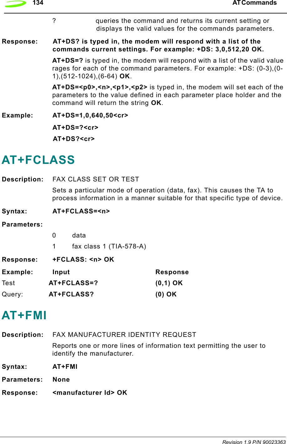
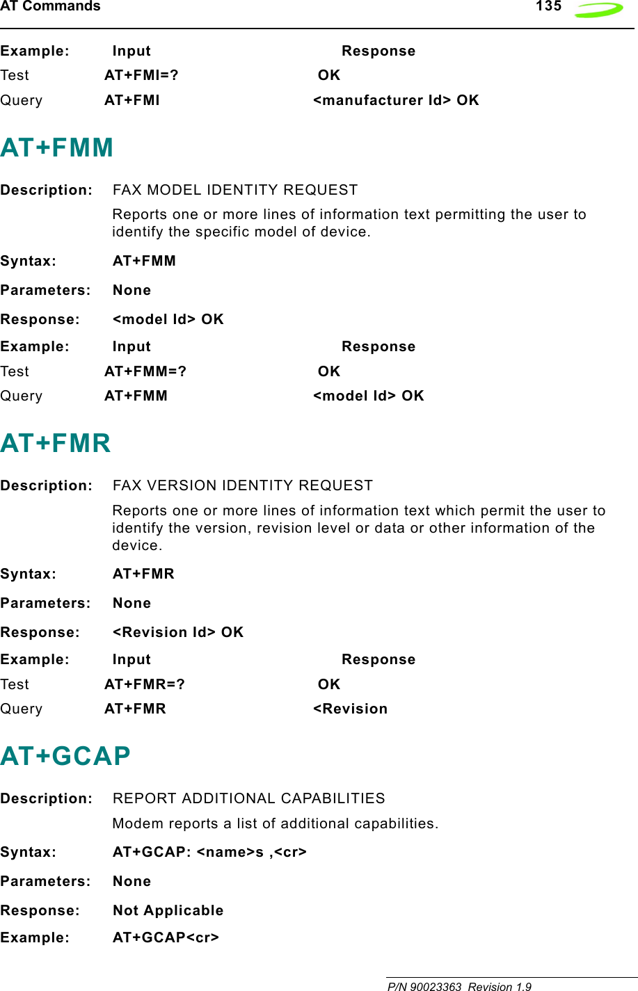
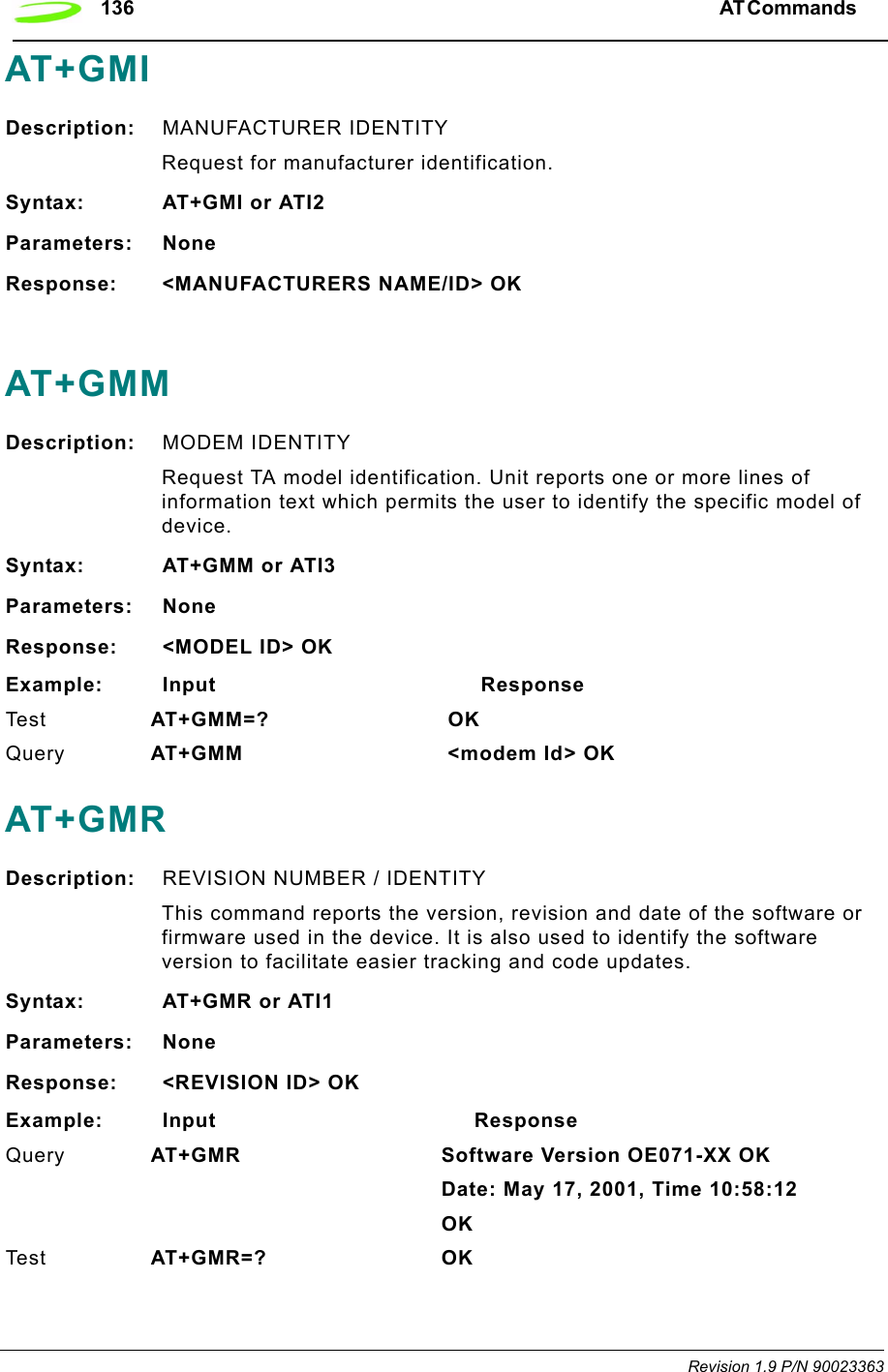
![AT Commands 137 P/N 90023363 Revision 1.9AT+GOIDescription: GLOBAL OBJECT IDENTITYReports one or more lines of information text which permits the user to identify the device, based on the ISO system for registering unique object identifiers.Syntax: AT+GOIParameters: NoneResponse: NULL ID OK<OBJECT ID> OK see X.208, 209 for the formatExample: AT+GOI=? <OBJECT ID> OKAT+GSNDescription: SERIAL NUMBER IDENTITYReports the IMEI (international mobile equipment identifier) number in information text which permits the user to identify the individual ME device. The serial number (IMEI) is varied by individual ME device.Syntax: AT+GSNParameters: NoneResponse: <SERIAL NUMBER> OKExample: Input ResponseTes t AT+GSN=? OKQuery AT+GSN <serial number> OKAT+ICFDescription: INTERFACE CHARACTER FRAMINGThis command setting determines the serial interface character framing format and parity received by TA from TE.Syntax: AT+ICF=[<format>,[<parity>]]Parameters:<format> 1 8 data 0 parity 2 stop2 8 data 1 parity 1 stop3 8 data 0 parity 1 stop4 7 data 0 parity 2 stop5 7 data 1 parity 1 stop6 7 data 0 parity 1 stop](https://usermanual.wiki/Novatel-Wireless/NRM-EG301.Revised-Users-manual/User-Guide-315684-Page-145.png)
![138 AT Commands Revision 1.9 P/N 90023363<parity> 0 odd1even2 mark (1) 3 space (0) The parity field is ignored if the format field specifies no parity.Response: +ICF: <format>,<parity> OKExample: Input ResponseTe s t AT+ICF=? +ICF: <format>,<parity> OKQuery AT+ICF? <3,3> OKAT+IFCDescription: LOCAL DATA FLOW CONTROLThis setting determines the data flow control on the serial interface for data mode.Syntax: AT+IFC=[<dce_by_dte>[,<dte_by_dce>]]Parameters:<dce_by_dte> specifies the method will be used by TE at receive of data from TA0None1 XON/XOFF, don’t pass characters on to data stack2 line 133: Ready for Receiving3 XON/XOFF, pass characters on to data stack<dte_by_dce> specifies the method will be used by TA at receive of data from TE0 None1 XON/XOFF2 line 106: Clear to send (CTS)Response: OKExample: Input ResponseTe s t AT+IFC=? OK](https://usermanual.wiki/Novatel-Wireless/NRM-EG301.Revised-Users-manual/User-Guide-315684-Page-146.png)