Northern Digital orporated VICRA POLARIS VICRA User Manual USERS MANUAL
Northern Digital Incorporated POLARIS VICRA USERS MANUAL
UserManual.wiki
>
Northern Digital orporated
>
VICRA User Manual
USERS MANUAL
Navigation menu
Upload a User Manual
Namespaces
Wiki Guide
HTML
PDF
Info
Views
User Manual
Discussion / Help
Navigation

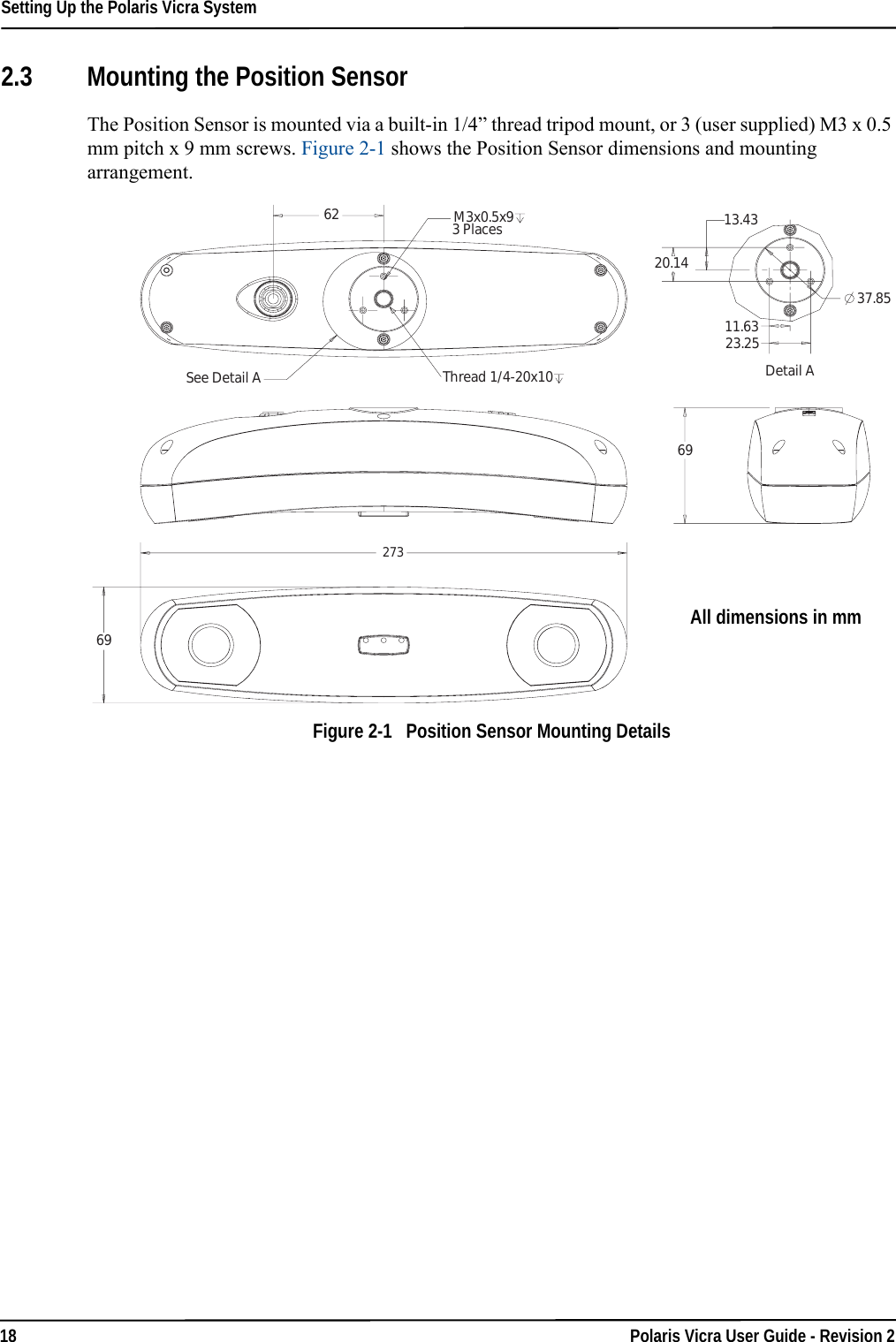
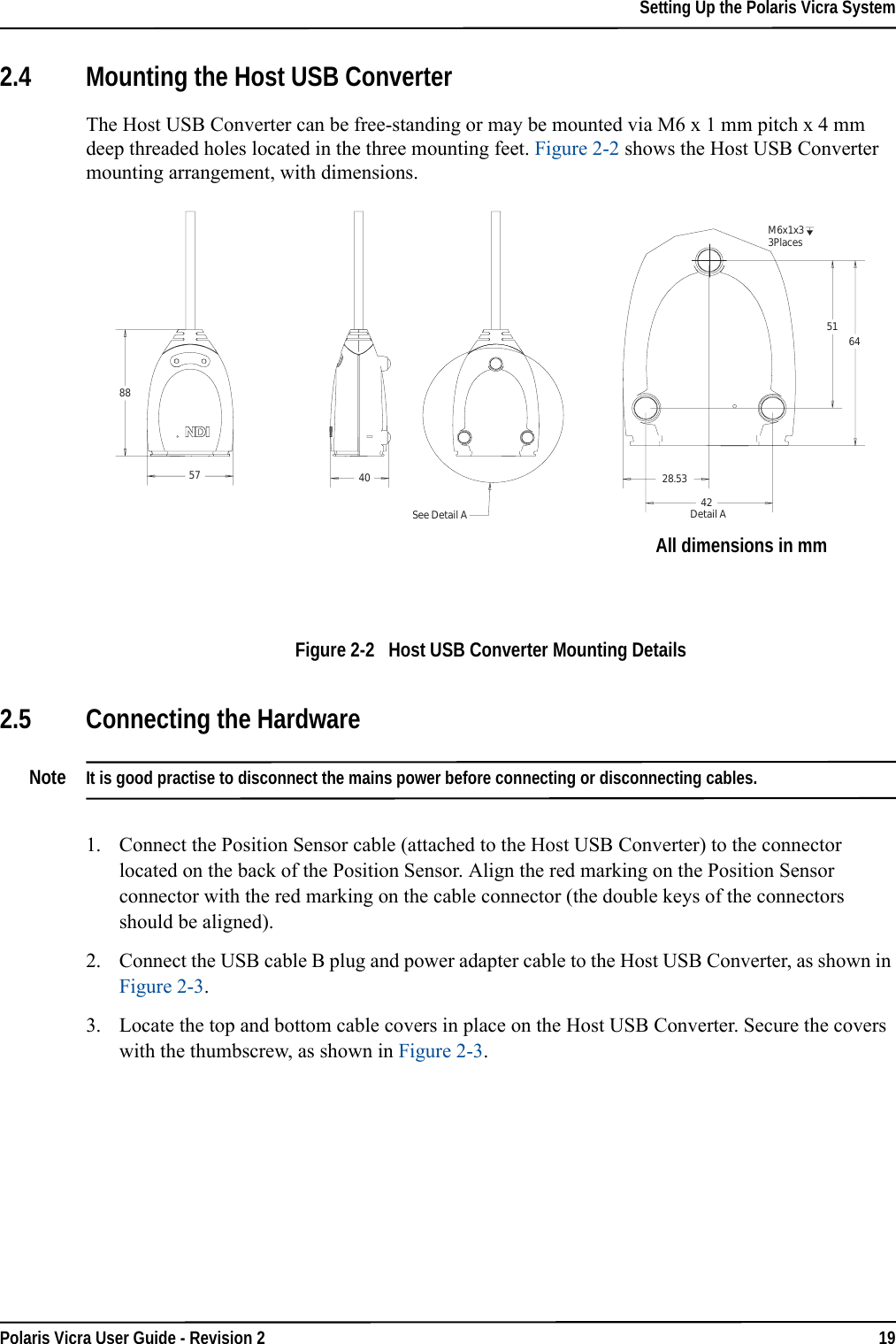
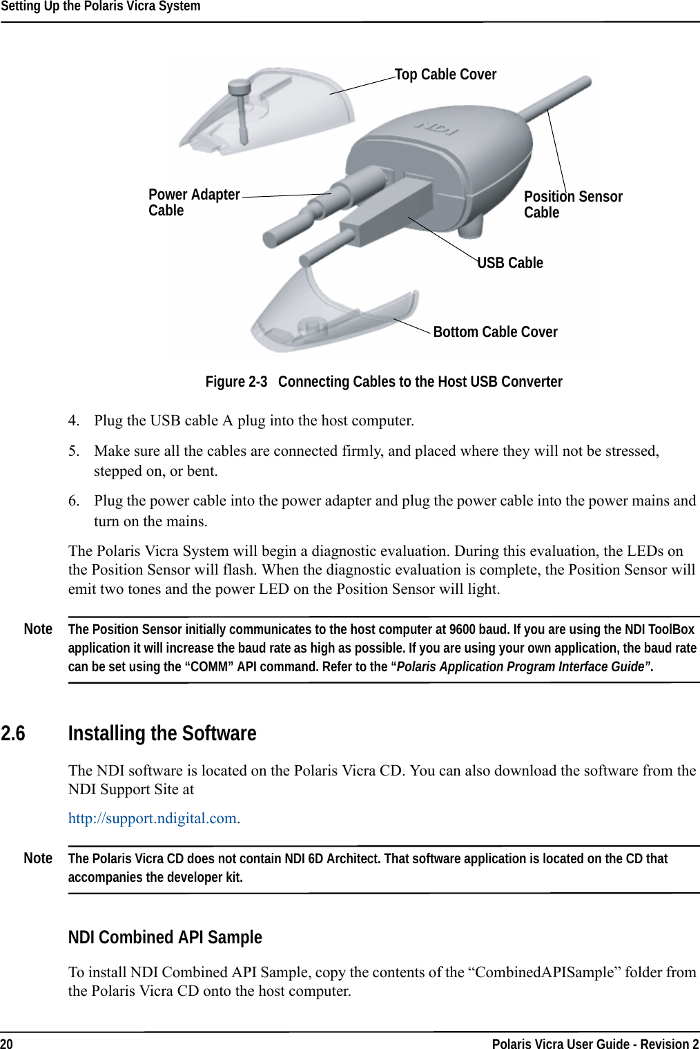


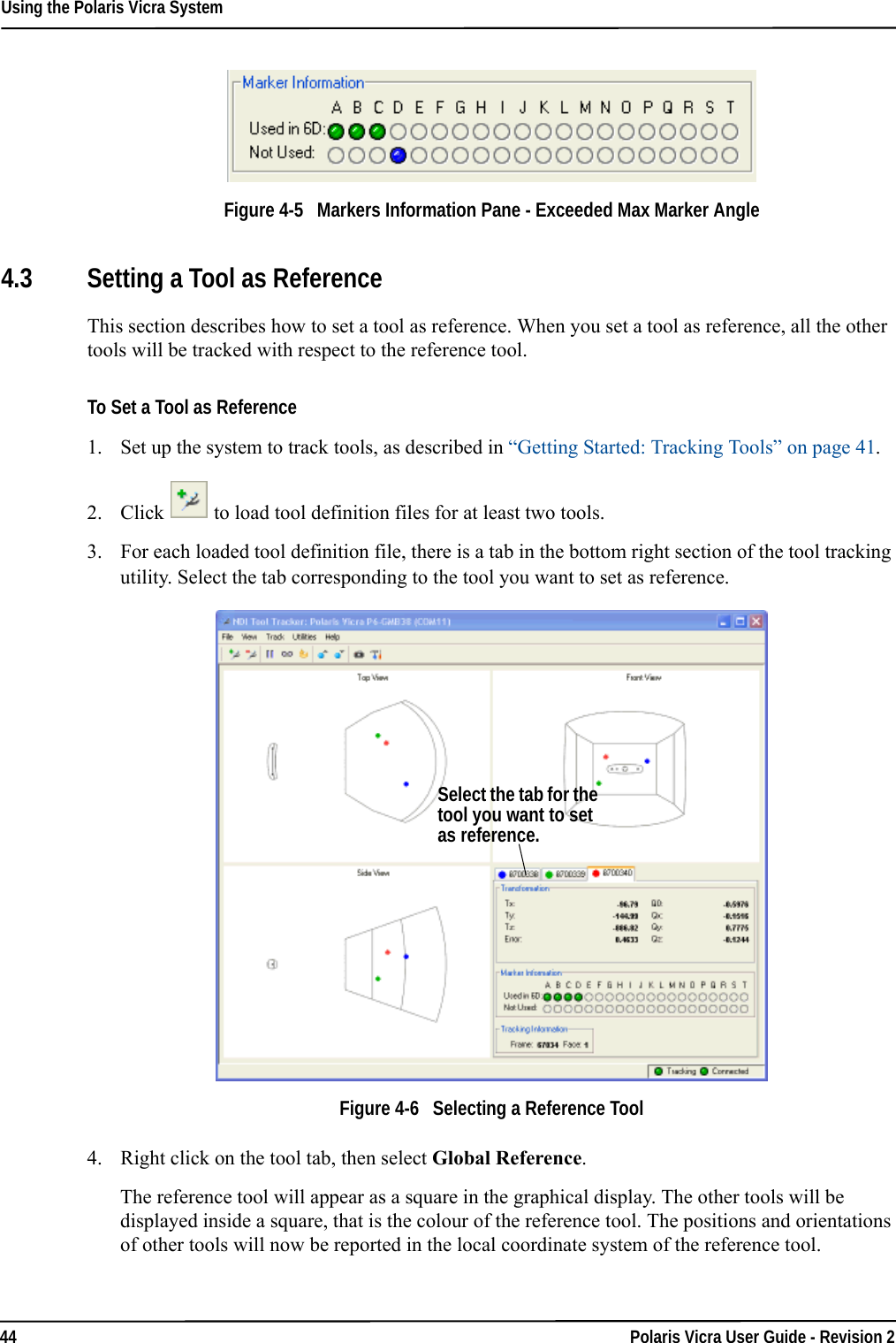
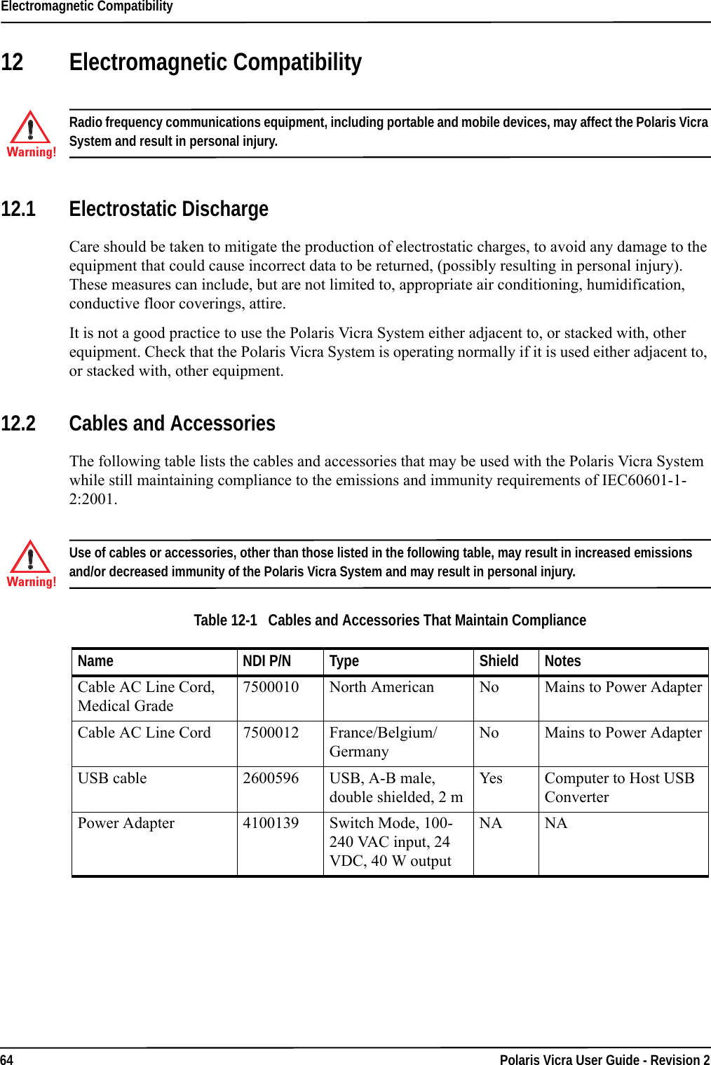
![Return Procedure and Warranty78 Polaris Vicra User Guide - Revision 2General Provisions Applicable to WarrantyNDI’s obligations under this warranty shall be limited to repairing or replacing (at NDI’s option) the product(s), EXW (Incoterms 2000) NDI’s plant (Waterloo, Ontario, Canada). Any original parts removed and/or replaced during any repair process shall become the property of NDI. This warranty shall apply only to the original Buyer [being that person or legal entity which has contracted directly with NDI for the supply of the product(s)]. Repair work shall be warranted on the same terms as stated herein except such warranty shall be for a period of sixty (60) days or for the remainder of the unexpired warranty period, whichever is longer. In respect of any product(s) supplied hereunder which are manufactured by others, NDI gives no warranty whatsoever, and the warranty given by such manufacturers, if any, shall apply. The obligations of NDI set forth in this warranty are conditional upon proper transportation, shipping, handling, storage, installation, use, maintenance and compliance with any applicable recommendations of NDI. Without limiting the generality of the foregoing, this warranty shall not apply to defects or damage resulting from: fire; misuse; abuse; accident; neglect; improper installation; improper care and/or maintenance; lack of care and/or maintenance; customer supplied software interfacing; modification or repair which is not authorized by NDI; power fluctuations; operation of hardware product(s) outside of environmental specifications; improper site preparation and maintenance; permitting any substance whatsoever to contaminate or otherwise interfere with optics; and any other cause beyond the control of NDI. The obligations set forth in this warranty are further conditional upon the Buyer promptly notifying NDI of any defect and, if required, promptly making the product(s) available for correction. NDI shall be given reasonable opportunity to investigate all claims and no product(s) shall be returned to NDI without NDI first providing the Buyer with a return material authorization number and shipping instructions. All product(s) returned to NDI shall be packaged in the containers originally used by NDI to ship the product(s) to the Buyer.NDI, for itself, its agents, contractors, employees, providers, and for any parent or subsidiary of NDI, expressly disclaims all warranties, express or implied, including, without limitation, of merchantability or fitness for a particular purpose.The foregoing warranty is the entire warranty of NDI. NDI neither assumes nor authorizes any person, purporting to act on its behalf, to modify or to change this warranty, or any other warranty or liability concerning the product(s).](https://usermanual.wiki/Northern-Digital-orporated/VICRA/User-Guide-599001-Page-90.png)