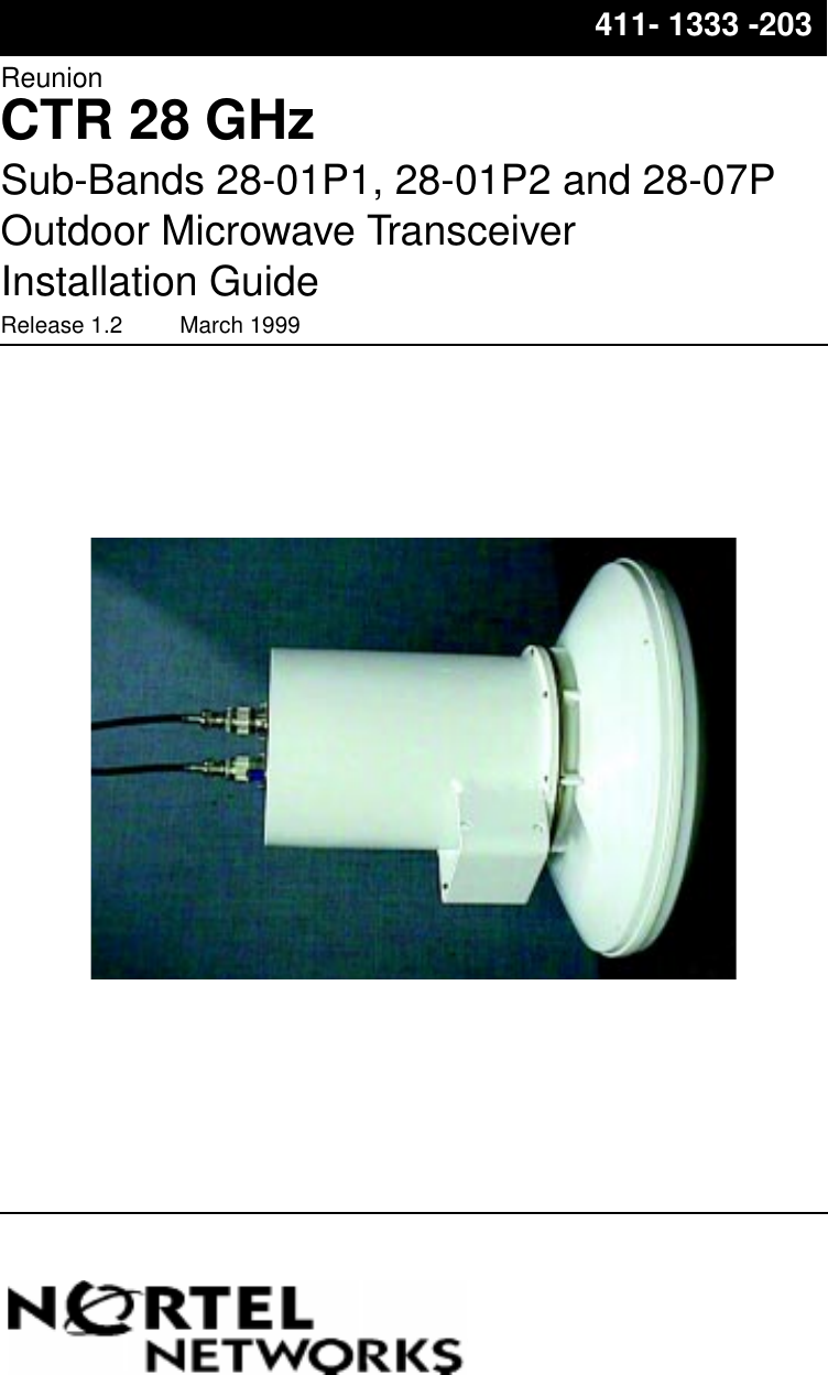
Nortel Networks CTR2807NT 28GHz Customer Premise LMDS Transceiver User Manual
Nortel Networks Inc. 28GHz Customer Premise LMDS Transceiver
UserManual.wiki
>
Nortel Networks
>
CTR2807NT User Manual
>
as distributed to customers
Contents
1.
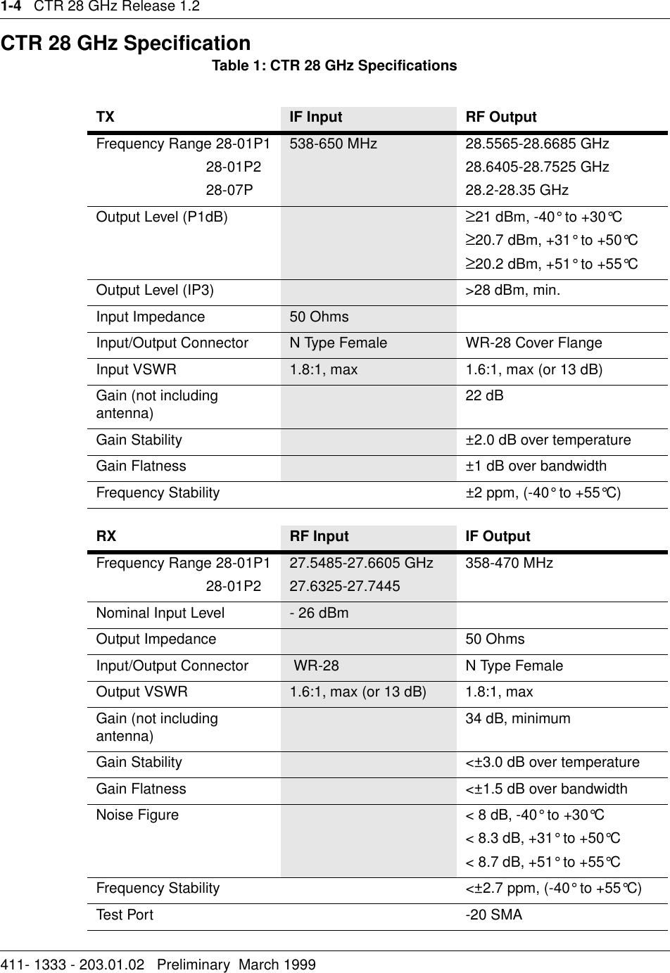
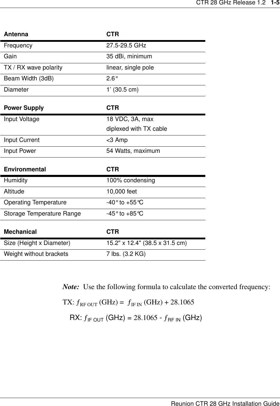
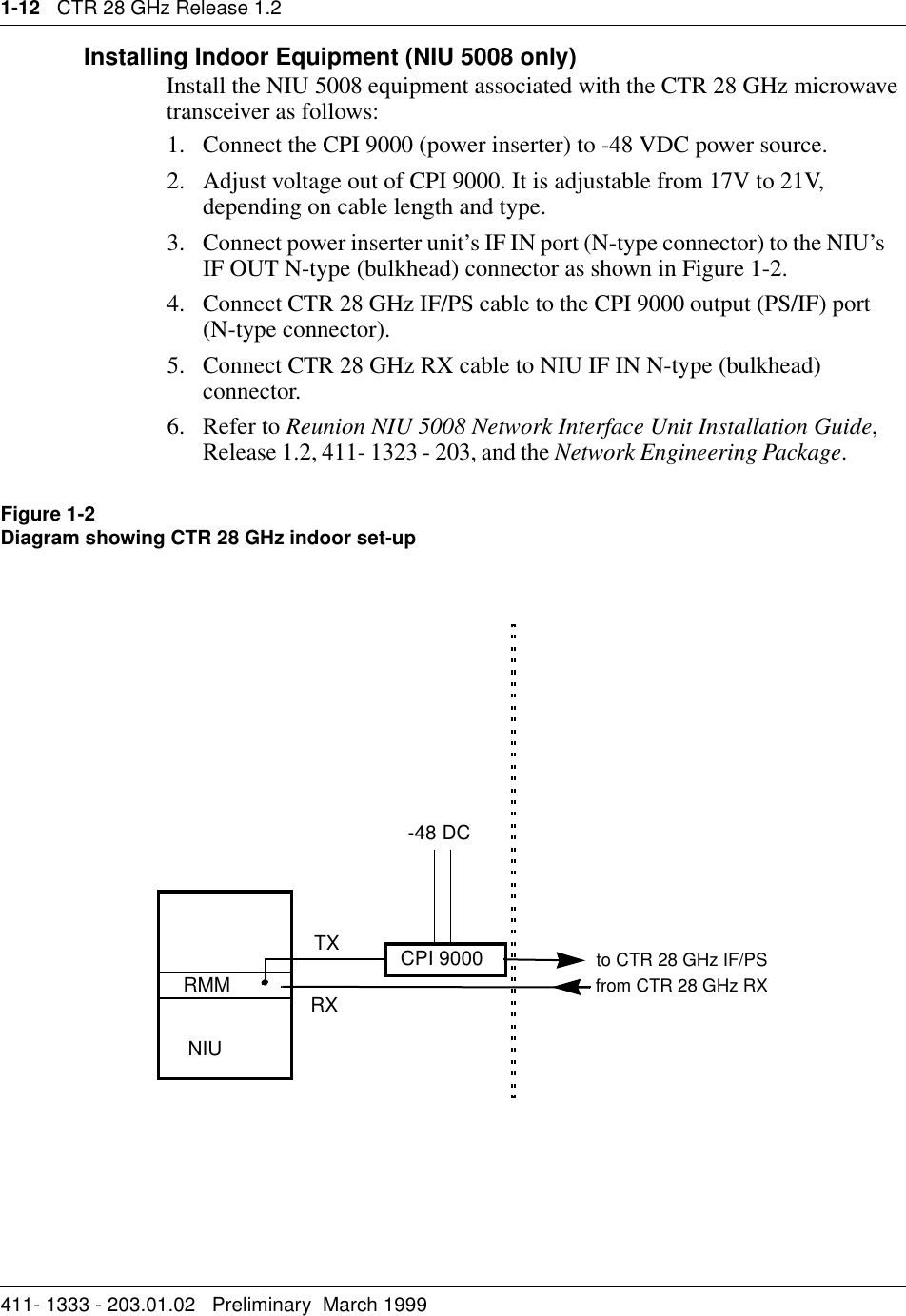
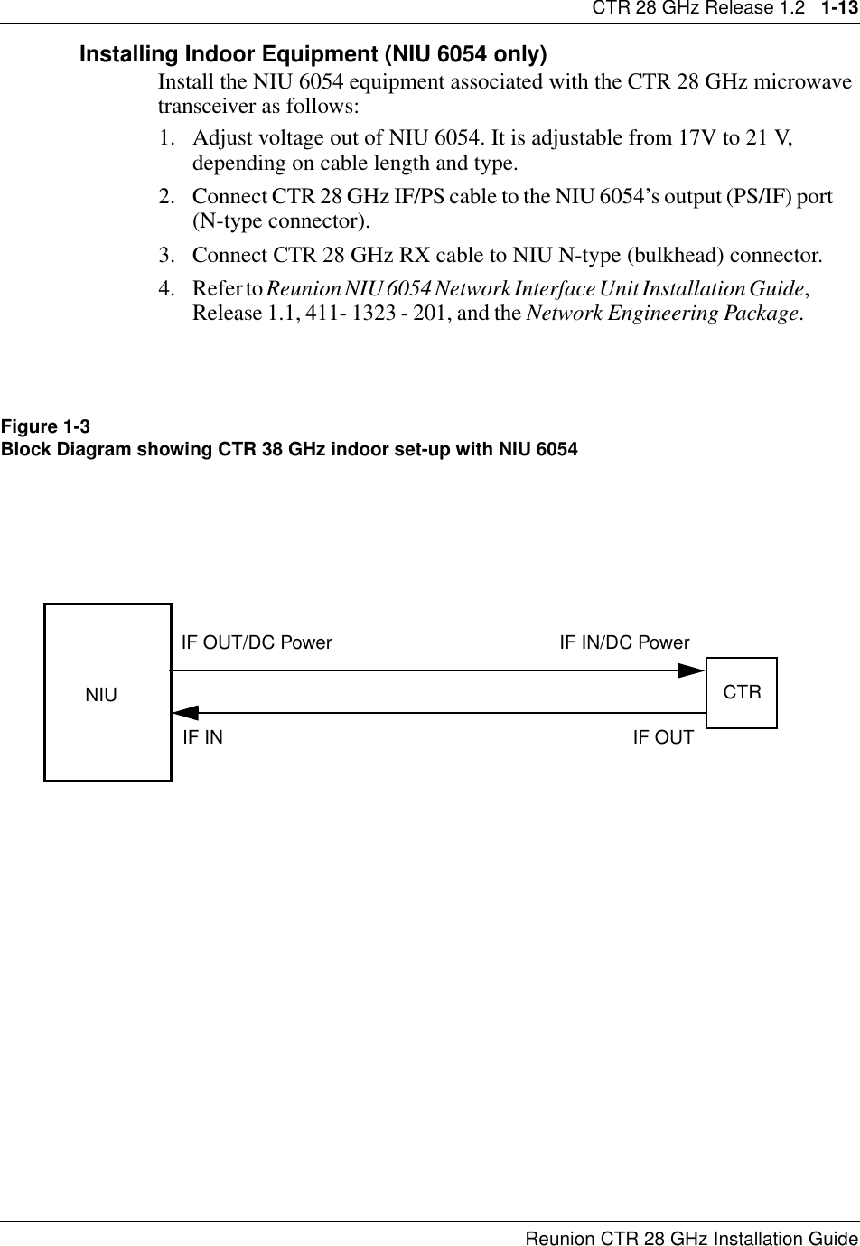
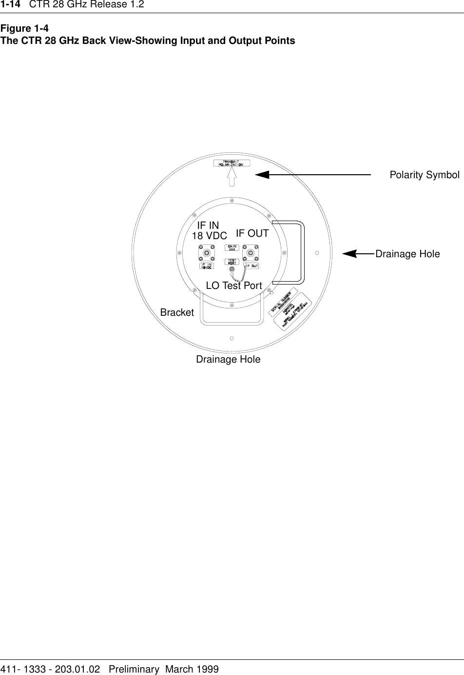
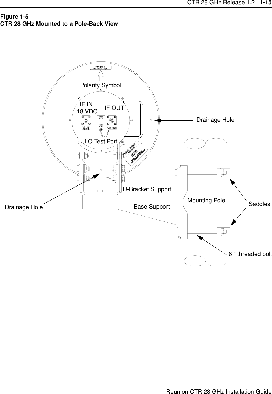
Usesr Manual
2.
as distributed to customers
as distributed to customers
Navigation menu
Upload a User Manual
Namespaces
Wiki Guide
HTML
PDF
Info
Views
User Manual
Discussion / Help
Navigation