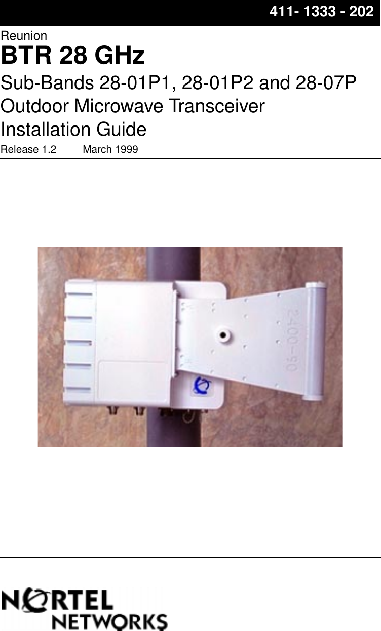
Nortel Networks BTR2807NT ReUnion LMDS Transceiver - 28GHz - option 7 User Manual
Nortel Networks Inc. ReUnion LMDS Transceiver - 28GHz - option 7
UserManual.wiki
>
Nortel Networks
>
BTR2807NT User Manual
>
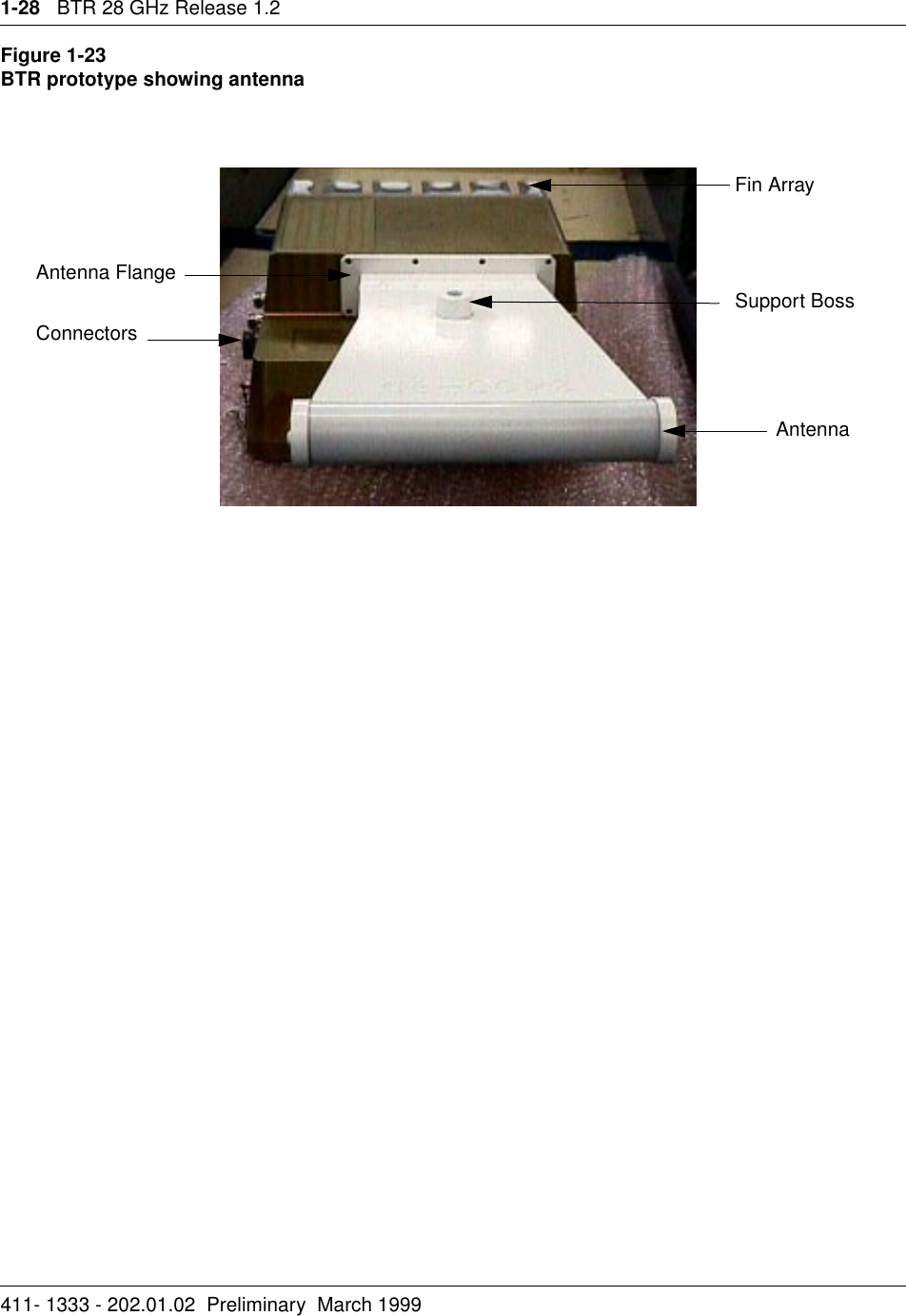
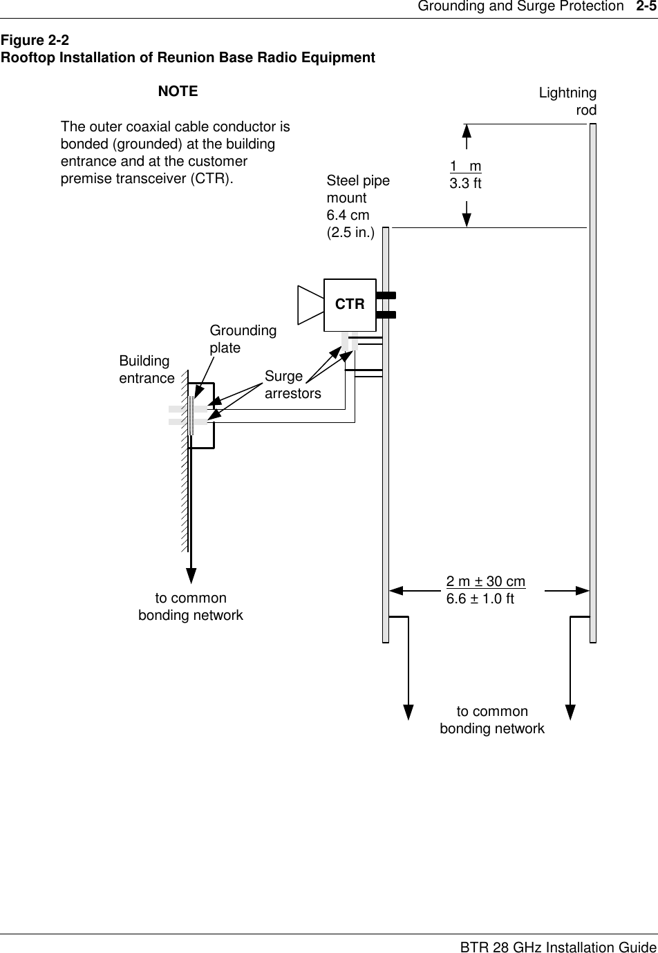
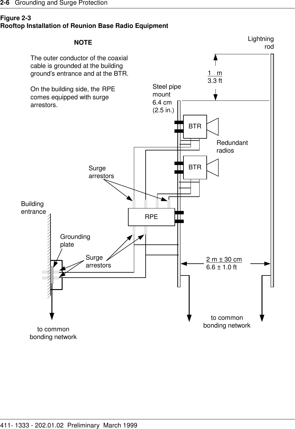
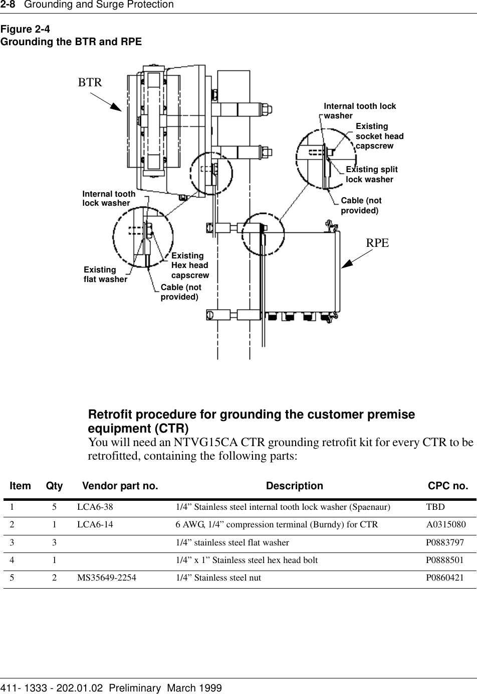
Base station
Contents
1.
Base station
2.
Customer station
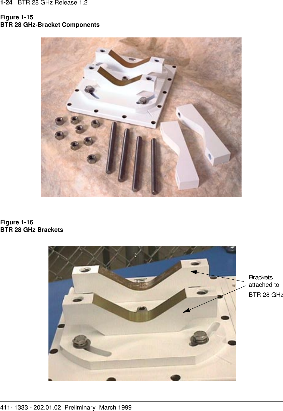
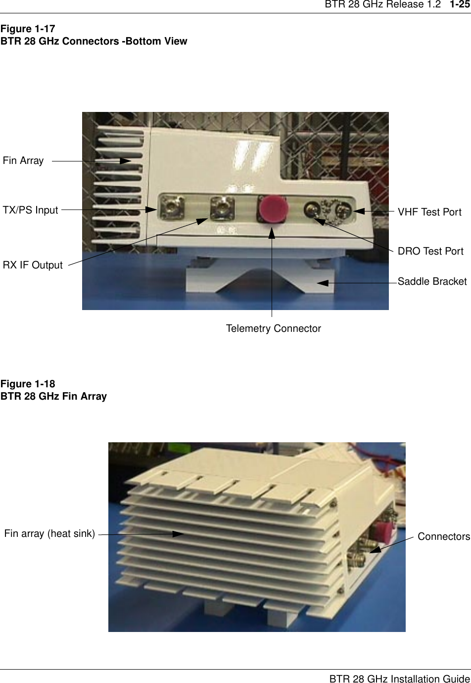
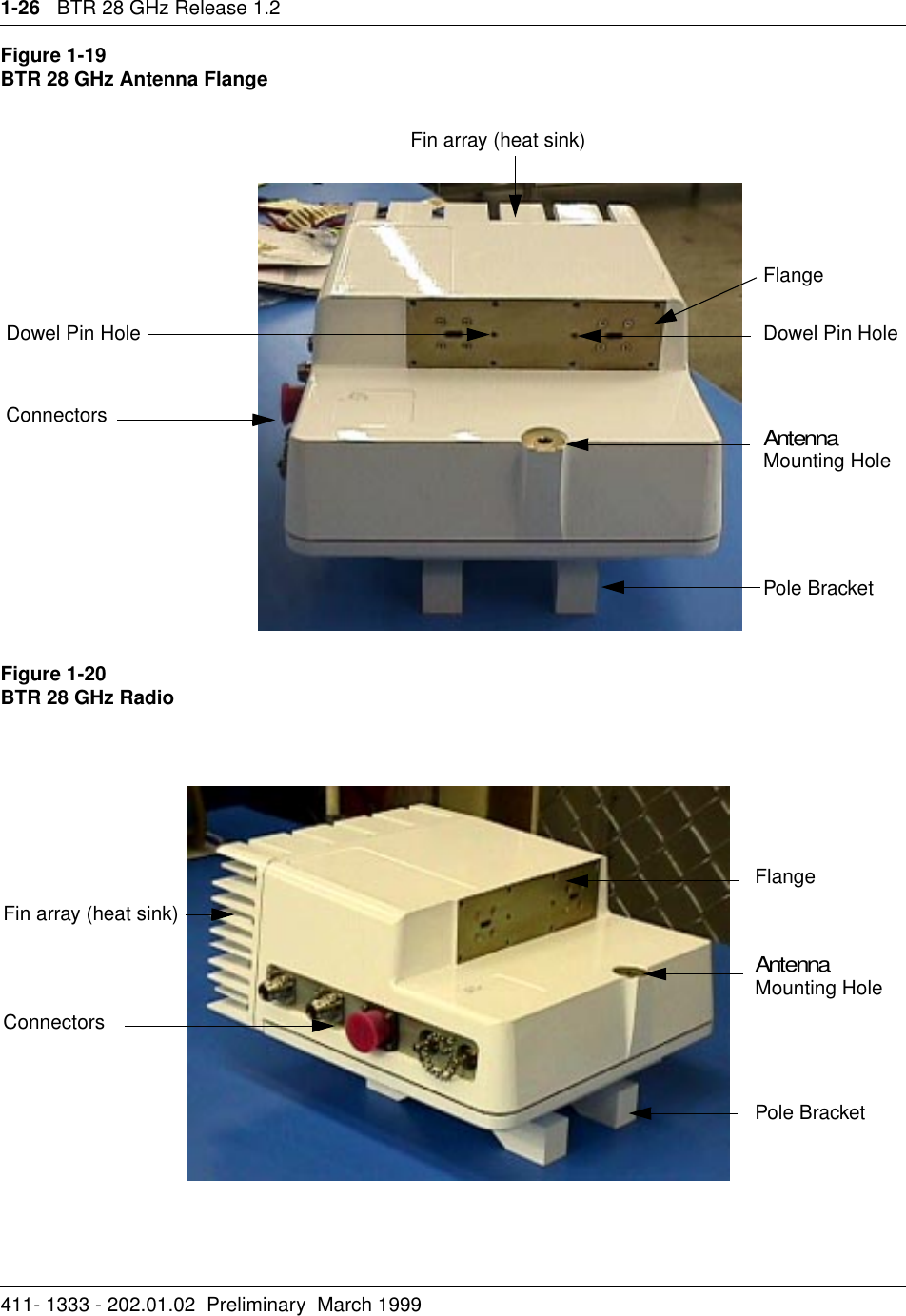
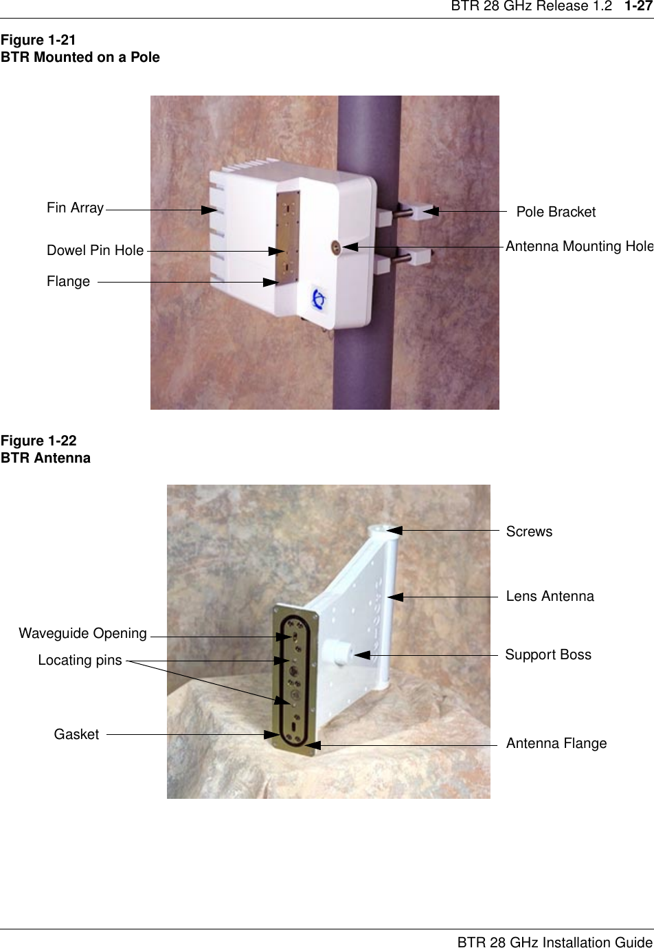
Base station
Navigation menu
Upload a User Manual
Namespaces
Wiki Guide
HTML
PDF
Info
Views
User Manual
Discussion / Help
Navigation