Nortel Networks 2332 802.11 A/B/G Access Point User Manual
Nortel Networks, Inc. 802.11 A/B/G Access Point
UserManual.wiki
>
Nortel Networks
>
2332 User Manual
>
User Manual
Contents
1.
User Manual
2.
Users Manual 2
3.
User Manual 1
User Manual
Navigation menu
Upload a User Manual
Namespaces
Wiki Guide
HTML
PDF
Info
Views
User Manual
Discussion / Help
Navigation
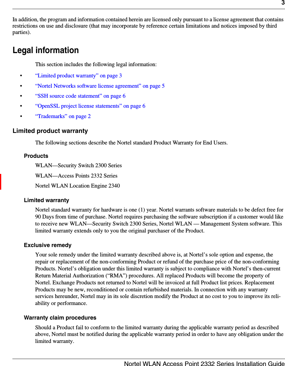
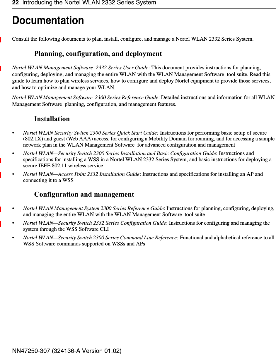
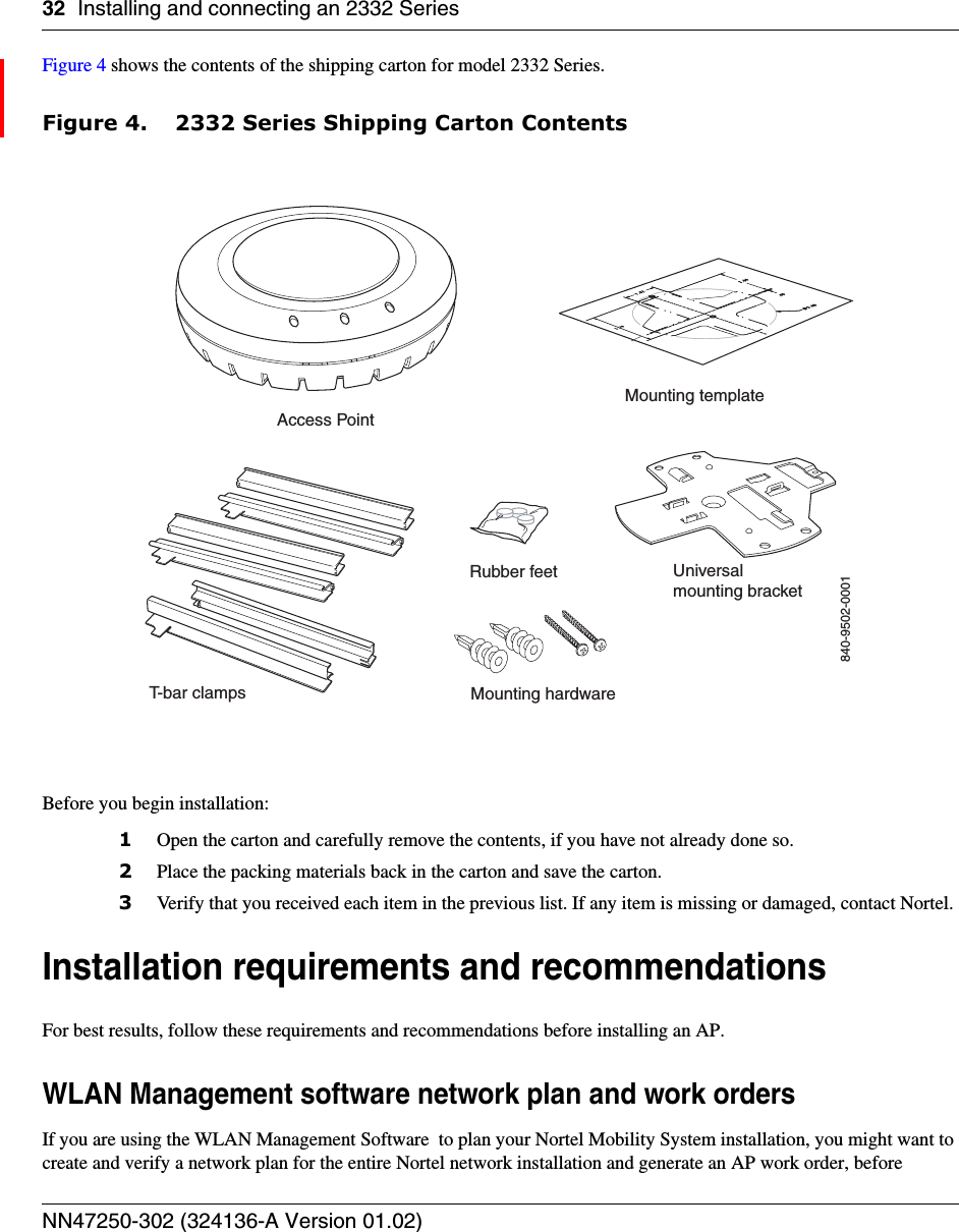
![Introducing the Nortel WLAN 2332 Series System 23Nortel WLAN Access Point 2332 Series Installation GuideSafety and advisory noticesThe following kinds of safety and advisory notices appear in this manual. (For translations of the warning conventions and of all warnings in this manual, see Appendix , “Translated caution statement, warning conventions and warning messages,” on page 113.) Text and syntax conventionsNortel manuals use the following text and syntax conventions: Caution! This situation or condition can lead to data loss or damage to the product or other property.Warning! This situation or condition can cause injury.Warning! High voltage. This situation or condition can cause injury due to electric shock.Note. This information is of special interest.Convention UseMonospace text Sets off command syntax or sample commands and system responses.Bold text Highlights commands that you enter or items you select.Italic text Designates command variables that you replace with appropriate values, or highlights publication titles or words requiring special emphasis.Menu Name > Command Indicates a menu item that you select. For example, File > New indicates that you select New from the File menu.[ ] (square brackets) Enclose optional parameters in command syntax.{ } (curly brackets) Enclose mandatory parameters in command syntax.| (vertical bar) Separates mutually exclusive options in command syntax.](https://usermanual.wiki/Nortel-Networks/2332.User-Manual/User-Guide-839781-Page-22.png)