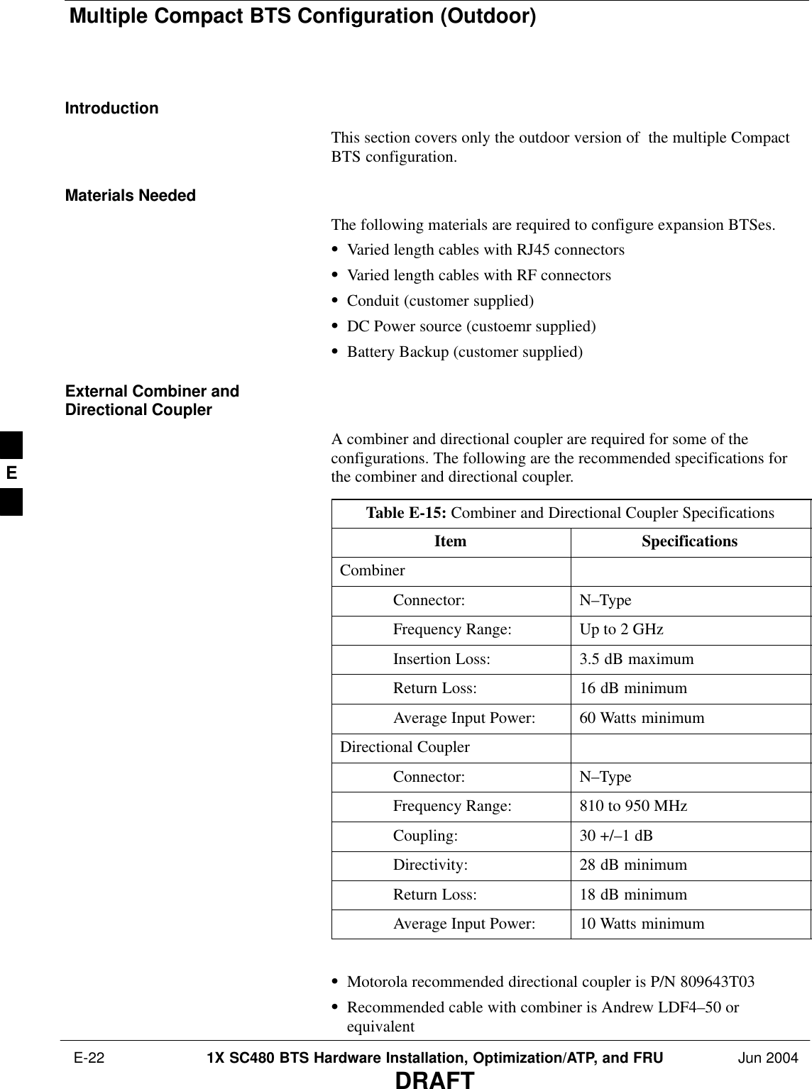
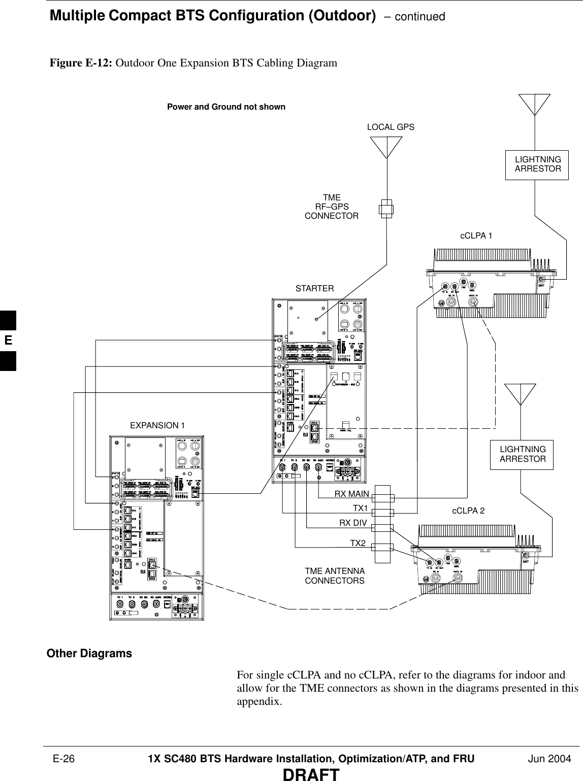
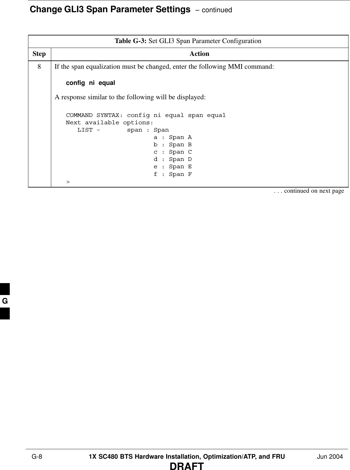
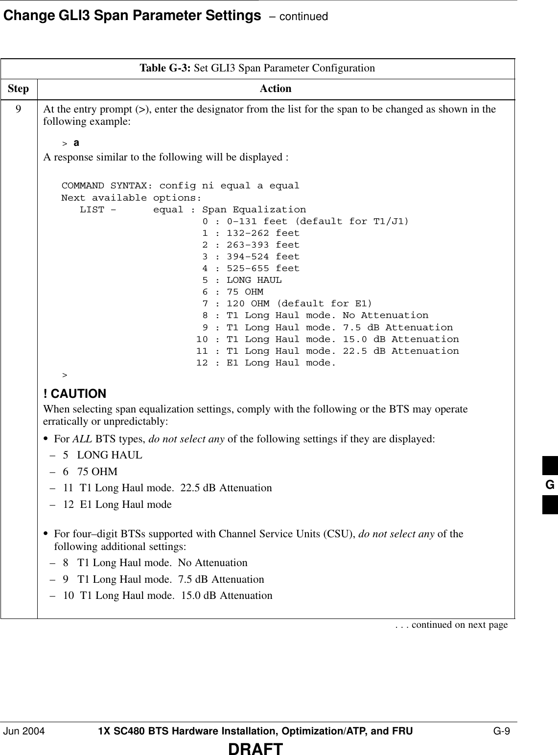
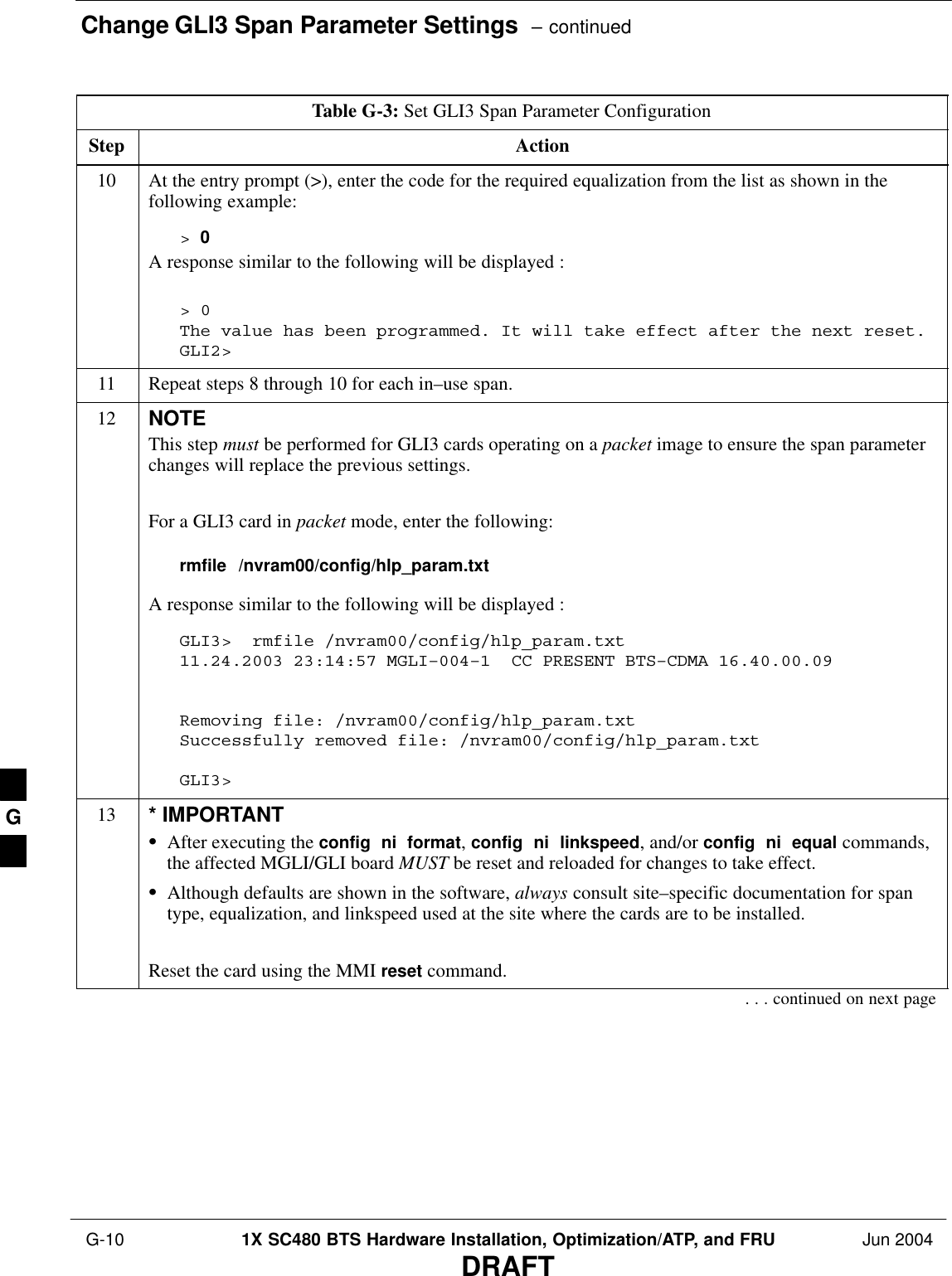
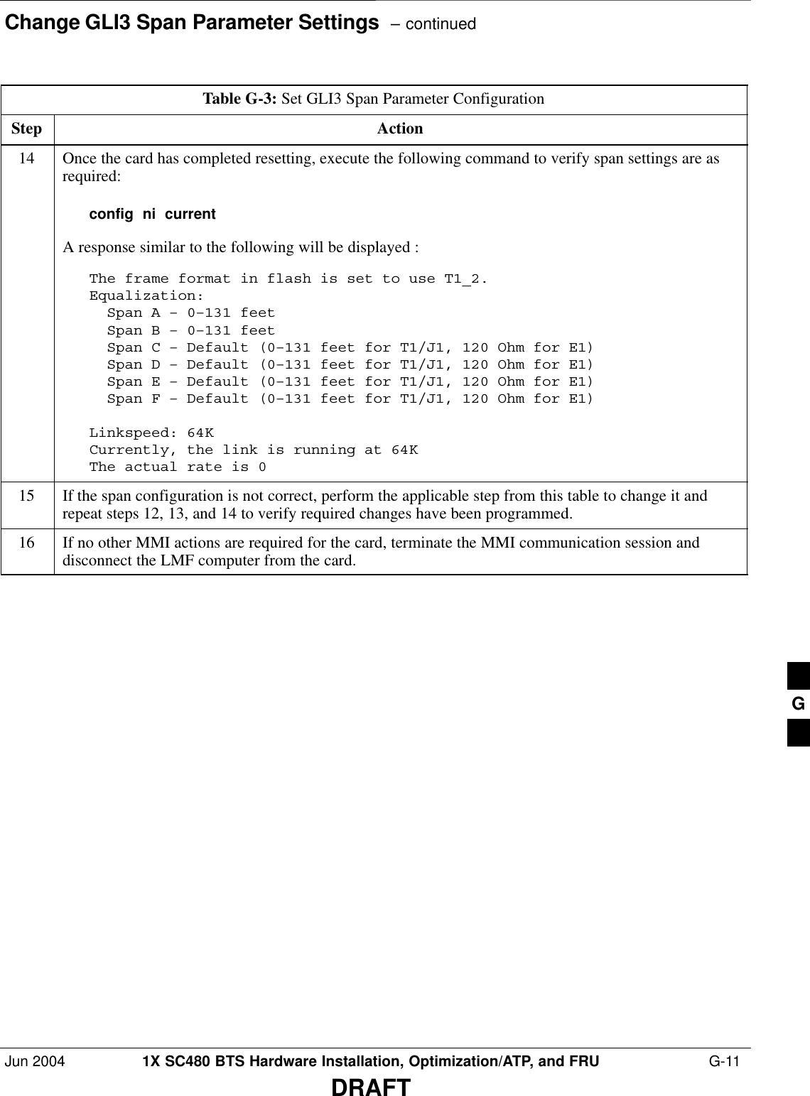
Nokia Solutions and Networks T6EK1 1X-EVDO SC480 BTS Microcell Base Station Transmtr User Manual print instructions

Nokia Solutions and Networks 1X-EVDO SC480 BTS Microcell Base Station Transmtr print instructions

User Manual 4 of 4

Compact BTS Expansion Configuration (Indoor)  – continued E-18 1X SC480 BTS Hardware Installation, Optimization/ATP, and FRU Jun 2004DRAFTFigure E-8: Two Expansion BTSes Cabling DiagramEXPANSION 2EXPANSION 1STARTERLOCAL GPSPower and Ground not shownEnsure that the expansionBTSes have the expansioncMPC cards installed.COMBINERTX 1RX MAINRX DIVTX 2DCLALALAE
Compact BTS Expansion Configuration (Indoor)  – continuedJun 2004 1X SC480 BTS Hardware Installation, Optimization/ATP, and FRU  E-19DRAFTEXPANSION 1STARTERLOCAL GPSFigure E-9: One Expansion BTS Cabling DiagramPower and Ground not shownEnsure that the expansionBTS has an expansion cMPCcard installed.TX 1RX MAINRX DIVLALALAE
Compact BTS Expansion Configuration (Indoor)  – continued E-20 1X SC480 BTS Hardware Installation, Optimization/ATP, and FRU Jun 2004DRAFTTable E-11: BBX (Carrier) to cCLPA Via RS485BTS cCLPAStarter – BBX1 cCLPA–1Starter – BBX4 cCLPA–1Expansion 1 – BBX1 cCLPA–2Expansion 1 – BBX4 cCLPA–2Expansion 2 – BBX1 cCLPA–1Expansion 2 – BBX4 cCLPA–1Expansion 3 – BBX1 cCLPA–2Expansion 3 – BBX4 cCLPA–2 Table E-12 shows in tabular format the BTS–to–cCLPA cabling ofFigure E-1.Table E-12: Starter and Three Expansion BTS Cabling for Circuit or Packet to Dual cCLPAsBTS cCLPAStarter – BBX1 CPA–A (CPA–1)Starter – BBX4 CPA–A (CPA–1)Expansion 1 – BBX1 CPA–B (CPB–2)Expansion 1 – BBX4 CPA–B (CPB–2)Expansion 2 – BBX1 CPA–A (CPA–1)Expansion 2 – BBX4 CPA–A (CPA–1)Expansion 3 – BBX1 CPA–B (CPA–2)Expansion 3 – BBX4 CPA–B (CPA–2) Starter and Two ExpansionBTSes to cCLPA CablingTable E-13 shows in tabular format the BTS–to–cCLPA cabling ofFigure E-2.E
Compact BTS Expansion Configuration (Indoor)  – continuedJun 2004 1X SC480 BTS Hardware Installation, Optimization/ATP, and FRU  E-21DRAFTTable E-13: Starter and Two Expansion BTS Cabling for Circuit or Packet to Dual cCLPAsBTS cCLPAStarter – BBX1 CPA–A (CPA–1)Starter – BBX4 CPA–A (CPA–1)Expansion 1 – BBX1 CPA–B (CPB–2)Expansion 1 – BBX4 CPA–B (CPB–2)Expansion 2 – BBX1 CPA–A (CPA–1)Expansion 2 – BBX4 CPA–A (CPA–1) Starter and One ExpansionBTS to cCLPA CablingTable E-14 shows in tabular format the BTS–to–cCLPA cabling ofFigure E-3.Table E-14: Starter and One Expansion BTS Cabling for Circuit or Packet to Dual cCLPAsBTS cCLPAStarter – BBX1 CPA–A (CPA–1)Starter – BBX4 CPA–A (CPA–1)Expansion 1 – BBX1 CPA–B (CPB–2)Expansion 1 – BBX4 CPA–B (CPB–2) E
Multiple Compact BTS Configuration (Outdoor) E-22 1X SC480 BTS Hardware Installation, Optimization/ATP, and FRU Jun 2004DRAFTIntroductionThis section covers only the outdoor version of  the multiple CompactBTS configuration.Materials NeededThe following materials are required to configure expansion BTSes.SVaried length cables with RJ45 connectorsSVaried length cables with RF connectorsSConduit (customer supplied)SDC Power source (custoemr supplied)SBattery Backup (customer supplied)External Combiner andDirectional CouplerA combiner and directional coupler are required for some of theconfigurations. The following are the recommended specifications forthe combiner and directional coupler.Table E-15: Combiner and Directional Coupler SpecificationsItem SpecificationsCombinerConnector: N–TypeFrequency Range: Up to 2 GHzInsertion Loss: 3.5 dB maximumReturn Loss: 16 dB minimumAverage Input Power: 60 Watts minimumDirectional CouplerConnector: N–TypeFrequency Range: 810 to 950 MHzCoupling: 30 +/–1 dBDirectivity: 28 dB minimumReturn Loss: 18 dB minimumAverage Input Power: 10 Watts minimum SMotorola recommended directional coupler is P/N 809643T03SRecommended cable with combiner is Andrew LDF4–50 orequivalentE
Multiple Compact BTS Configuration (Outdoor)  – continuedJun 2004 1X SC480 BTS Hardware Installation, Optimization/ATP, and FRU  E-23DRAFTSDirectional coupler and combiner are not environmentally protected ,and so must be placed within the TME.ExpansionCompact BTSInstallation ProcedureFollow the procedure in Table E-16for installation of multiple CompactBTSes.Table E-16: Procedure for Installing Expansion Compact BTSesStep Action1Follow the procedure in Chapter 4 for installing a Compact BTS in a rack.2For a 3 BTS expansion configuration, follow Figure E-1. Proceed to step 3.2a For a 2 BTS expansion configuration, follow Figure E-2. Proceed to step 3.2b For a 1 BTS expansion configuration, follow  Figure E-3. Proceed to step 3.3If conduit is not used, dress cables as necessary.4Perform Optimization and ATP as described in Chapter 6. LMF Help provides further information.  Frame ID Switch SettingsRefer to Chapter 5, Figure 5-1 or Figure 5-2 or Table 5-1 throughTable 5-4 for the Frame DIP Switch settings.E
Multiple Compact BTS Configuration (Outdoor)  – continued E-24 1X SC480 BTS Hardware Installation, Optimization/ATP, and FRU Jun 2004DRAFTFigure E-10: Three Expansion BTSes Cabling DiagramLIGHTNINGARRESTORLIGHTNINGARRESTOREXPANSION 3EXPANSION 2EXPANSION 1STARTERcCLPA 1cCLPA 2LOCAL GPSTX1TX2RX DIVRX MAINTME ANTENNACONNECTORSTMERF–GPSCONNECTORPower and Ground not shownE
Multiple Compact BTS Configuration (Outdoor)  – continuedJun 2004 1X SC480 BTS Hardware Installation, Optimization/ATP, and FRU  E-25DRAFTFigure E-11: Outdoor Two Expansion BTSes Cabling DiagramLIGHTNINGARRESTORLIGHTNINGARRESTOREXPANSION 2EXPANSION 1STARTERcCLPA 1cCLPA 2LOCAL GPSTMERF–GPSCONNECTORTX2TX1RX MAINRX DIVTME ANTENNACONNECTORSPower and Ground not shownE
Multiple Compact BTS Configuration (Outdoor)  – continued E-26 1X SC480 BTS Hardware Installation, Optimization/ATP, and FRU Jun 2004DRAFTLIGHTNINGARRESTORLIGHTNINGARRESTOREXPANSION 1STARTERcCLPA 1cCLPA 2LOCAL GPSFigure E-12: Outdoor One Expansion BTS Cabling DiagramTMERF–GPSCONNECTORTX1RX MAINRX DIVTX2TME ANTENNACONNECTORSPower and Ground not shownOther DiagramsFor single cCLPA and no cCLPA, refer to the diagrams for indoor andallow for the TME connectors as shown in the diagrams presented in thisappendix.E
Jun 2004 1X SC480 BTS Hardware Installation, Optimization/ATP, and FRUDRAFTAppendix F: Logical BTS Configuration Appendix ContentLogical BTS LAN Configuration for Compact BTS (Indoor) F-1 . . . . . . . . . . . . . . Introduction F-1 . . . . . . . . . . . . . . . . . . . . . . . . . . . . . . . . . . . . . . . . . . . . . . Materials Needed F-1 . . . . . . . . . . . . . . . . . . . . . . . . . . . . . . . . . . . . . . . . . . BTS ID Switch Settings F-1 . . . . . . . . . . . . . . . . . . . . . . . . . . . . . . . . . . . . . Logical BTS LAN Cabling Installation Procedure F-3 . . . . . . . . . . . . . . . . F
Table of Contents  – continued1X SC480 BTS Hardware Installation, Optimization/ATP, and FRU Jun 2004DRAFTNotesF
Logical BTS LAN Configuration for Compact BTS (Indoor)Jun 2004 1X SC480 BTS Hardware Installation, Optimization/ATP, and FRU  F-1DRAFTIntroductionThis appendix covers only the Logical BTS configuration for cicruitCompact BTS. The diagrams cover only the LAN connections. Thisconfiguration is set up to be used only with other Compact BTSes.Power and ground cabling are not shown.The LAN operates at 10Mbps which is an ethernet standard. It providesan interface for each GLI in the confiiguration.Refer to Figure 6-1 for location of the LAN connectors. In circuit mode,the LAN connections are used by the LMF to download data, and for usein calibration, acceptance testing, and optimization.Use these diagrams in conjunction with the diagrams for expansionBTSes in Appendix E.Logical BTS for 1.9 GHz, +27V A or B band circuit configurations isnot supported.Materials NeededThe following materials are required to configure LAN connectionsBTSes.S7 – RG–58 U cables (Length depends on spacing)S14 – BNC, Terminaton  Resistor Plugs (IEC 169–8 spec)S2 – BNC, 50 Ohm terminationsBTS ID Switch SettingsRefer to Chapter 5, Figure 5-1 or Figure 5-2 or Table 5-1 throughTable 5-4 for the BTS DIP Switch settings.EXPANSION 3EXPANSION 2EXPANSION 1STARTERFigure F-1: Three Expansion BTSes LAN Cabling DiagramAout BoutAin Bin Aout BoutAin Bin Aout BoutAin Bin Aout BoutAin Bin50–ohmLoads50–ohmLoadsF
Logical BTS LAN Configuration for Compact BTS (Indoor)  – continued F-2 1X SC480 BTS Hardware Installation, Optimization/ATP, and FRU Jun 2004DRAFTEXPANSION 2EXPANSION 1STARTERFigure F-2: Two Expansion BTSes LAN Cabling DiagramAout BoutAin Bin Aout BoutAin Bin Aout BoutAin Bin50–ohmLoads50–ohmLoadsEXPANSION 1STARTERFigure F-3: One Expansion BTS LAN Cabling DiagramAout BoutAin Bin Aout BoutAin Bin 50–ohmLoads50–ohmLoadsF
Logical BTS LAN Configuration for Compact BTS (Indoor)  – continuedJun 2004 1X SC480 BTS Hardware Installation, Optimization/ATP, and FRU  F-3DRAFTLogical BTS LAN CablingInstallation ProcedureFollow the procedure in Table F-1 for installation of LAN cables forLogical BTS.Table F-1: Procedure for Installing LAN Cabling for Logical BTSStep Action1Follow the procedure in Chapter 4 for installing a Compact BTS in a rack.2For a 3 BTS expansion configuration, follow Figure F-1. Proceed to step 3.2a For a 2 BTS expansion configuration, follow Figure F-2. Proceed to step 3.2b For a 1 BTS expansion configuration, follow  Figure F-3. Proceed to step 3.3Route LAN cables through conduit from Starter to Expansion BTS 1.4Route LAN cables through conduit from Starter to Expansion BTS 2 or 3  (depending onconfiguration).5If in use, route LAN cables from Expansion BTS 1 to Expansion BTS 2.6If in use, route LAN cables from Expansion BTS 2 to Expansion BTS 3.7Ensure that unused LAN connections are terminated in 50 ohms.8If not already performed, proceed to Appendix E for expansion cabling diagrams.9Perform Optimization and ATP as described in Chapter 6. LMF Help provides further information.   F
Logical BTS LAN Configuration for Compact BTS (Indoor)  – continued F-4 1X SC480 BTS Hardware Installation, Optimization/ATP, and FRU Jun 2004DRAFTNotesF
Jun 2004 1X SC480 BTS Hardware Installation, Optimization/ATP, and FRUDRAFTAppendix G: Integrated BTS Router Preliminary Operations Appendix ContentIntegrated BTS Router Preliminary Operations – Introduction G-1 . . . . . . . . . . . . . Introduction G-1 . . . . . . . . . . . . . . . . . . . . . . . . . . . . . . . . . . . . . . . . . . . . . . Preliminary Operations G-1 . . . . . . . . . . . . . . . . . . . . . . . . . . . . . . . . . . . . . When to Perform the Verifications G-1 . . . . . . . . . . . . . . . . . . . . . . . . . . . . Verify GLI3 Software Version and Span Parameter Settings G-2 . . . . . . . . . . . . . . . Verify GLI3 Software Version and Span Parameter Settings G-2 . . . . . . . . Required Items G-2 . . . . . . . . . . . . . . . . . . . . . . . . . . . . . . . . . . . . . . . . . . . . Verifying GLI3 Software Version and Span Parameter Settings G-2 . . . . . . Change GLI3 Span Parameter Settings G-6 . . . . . . . . . . . . . . . . . . . . . . . . . . . . . . . Change GLI3 Span Parameter Configuration G-6 . . . . . . . . . . . . . . . . . . . . G
Table of Contents  – continued1X SC480 BTS Hardware Installation, Optimization/ATP, and FRU Jun 2004DRAFTNotesG
Integrated BTS Router Preliminary Operations – IntroductionJun 2004 1X SC480 BTS Hardware Installation, Optimization/ATP, and FRU  G-1DRAFTIntroductionThe information and procedures provided are performed in cases wherethe GLI3 load and span parameters need to be verified.Preliminary OperationsImplementing the Integrated BTS Router (IBR) function requires somepreliminary checks of the GLI3 cards which will be used. This appendixprovides the procedures to accomplish these checks. The checks are:SVerification that IBR–capable software is installed on GLI3 cardswhich will be used for IBRSVerification that span parameter settings on GLI3 cards match therequirement for the spans at the BTS where the cards will be installed.When to Perform theVerificationsAll preliminary verifications provided in this chapter can be performedat either the BTS site or in a central facility equipped to power–up theGLI3 cards. Depending on the circumstances of the cards’ use, however,it may be advantageous in reducing the on–site upgrade time andlogistics to perform some of the verifications prior to installation at theBTS site. Table G-1 lists card conditions of use and the correspondingsuggested verification locations for the software version and spanparameter settings.Table G-1: Suggested Preliminary Verification LocationsGLI3 Card Condition InstallationLocation Software VersionVerificationLocationSpan ParameterSettings VerificationLocationInstalled and operating(circuit or packet) Site where installed At site Not required unlessspan type willchangeDifferent operatingsite from wherecurrently installedAt site wherecurrently installed Before or afterinstallation atdifferent site G
Verify GLI3 Software Version and Span Parameter Settings G-2 1X SC480 BTS Hardware Installation, Optimization/ATP, and FRU Jun 2004DRAFTVerify GLI3 Software Versionand Span Parameter SettingsSoftware Version Verification – Before upgrading a BTS to packetbackhaul with an IBR, the software version installed in the GLI3 card orcards must be verified. If the installed software version does not supportIBR functionality, it must be upgraded to a version which does. For BTSsites which are already in operation, the upgrade can be done through anetwork download to the GLI3 once it is installed. For cards to beinstalled in new BTS sites not previously in operation, the upgraderequires special procedures, and must be done with Motorola FieldOperations or Account Team assistance.Span Parameter Settings – Prior to initializing a GLI3 card for the firsttime in a live circuit BTS or IBR packet BTS site, the span parametersettings in the card must be verified as matching those provisioned in theOMC–R database. If the settings are not correct, the card will be unableto communicate with the RAN network elements and the site will not gointo service. Procedures are included in this section to change the GLI3card span parameter settings if this is necessary to match those requiredfor the BTS.Required ItemsThe following items are required to perform the verification:SLocal Maintenance Facility (LMF) computer with the LMFapplication program version installed which is compatible with thesoftware release installed on the BSS refer to Chapter 6Optimization/ATP in this manual.SOne of the following– Motorola cable part number CGDSMMICABLE219112– Fabricated DB–9 receptacle–to–8–contact MMI connector cable(see the MMI Cable Fabrication Section of Appendix D forfabrication instructions and Figure 6-9 for connection)– SLN2006A MMI Interface Kit (this kit is no longer available toorder), consisting of the following:–– Motorola Model TRN9666A null modem board–– Motorola 3009786R01 MMI cable or equivalentS(For use with SLN2006A only) Straight–through RS–232 cable,DB–9 to DB–9, and DB–9 to DB–25 connector adapter (seeFigure D-1)Verifying GLI3 SoftwareVersion and Span ParameterSettingsFollow the procedure in Table G-2 to verify GLI3 card software versionand span parameter settings.G
Verify GLI3 Software Version and Span Parameter Settings  – continuedJun 2004 1X SC480 BTS Hardware Installation, Optimization/ATP, and FRU  G-3DRAFTTable G-2: Verify GLI3 Software Version and Span Parameter SettingsStep Action1If it has not been done, start a GLI3 MMI communication session on the LMF computer as describedin Table 6-11.2Verify the installed software version by entering the following at the GLI3 prompt:display version3Response to the command will depend on the operating mode of the card. Responses similar to thefollowing will be displayed for:3a – Cards in circuit mode:GLI3>  display version01.09.1980 20:01:59 MGLI–002–2  OOS–SBY   BTS–CDMA 16.41.200.14 RAM version: 16.41.200.14ROM version: 16.41.200.14Built: Tue Oct 21 09:52:28 2003 il27–2112Bootrom version: 16.41.200.12Bootrom Built: Thu Oct  2 03:11:34 2003 IL27–0775Bootblock version: 16.1.59.00Bootblock Built: Wed Apr 10 07:08:06 2002 RIPCORD004This GLI board is in RAMBooted from /nvram00/loads/gli3_ckt_rom_upgrade.elfNext boot from /nvram00/loads/gli3_ckt_rom_upgrade.elfGLI3>  . . . continued on next page G
Verify GLI3 Software Version and Span Parameter Settings  – continued G-4 1X SC480 BTS Hardware Installation, Optimization/ATP, and FRU Jun 2004DRAFTTable G-2: Verify GLI3 Software Version and Span Parameter SettingsStep Action3b – For cards in packet mode:GLI3>  display version03.23.2004 18:16:07 MGLI–250–1  CC PRESENT BTS–CDMA 16.41.00.11 INTERNAL RAM VERSION: 16.41.0.11RAM Built: Tue Mar  2 04:59:33 2004 il27–2112BOOTROM VERSION: 16.41.00.08BOOTROM Built: Tue Feb 17 10:52:27 2004 il27–0507BOOTBLOCK VERSION: 16.1.59.00BOOTBLOCK Built: Wed Apr 10 07:08:06 2002 RIPCORD004SYSTEM VERSION: 2.16.4.50.15 COMMITTED VERSION: 2.16.4.50.15 NEXT VERSION: 2.16.4.50.15 BACK UP VERSION 2.16.4.50.10 CURRENT RELEASE PATH: /nvram00/screl/2.16.4.50.15/ CURRENT LIF: /nvram00/screl/2.16.4.50.15/NE_LIF.xml CURRENT IMAGE: /nvram00/screl/2.16.4.50.15/gli_ram.bin.0108 CODE SERVER: 128.0.0.1 GLI3>  4Note the bootROM or System version numbers displayed and determine if the GLI3 is loaded withIBR–capable code as follows:SIf the booROM version number is 2.16.41.00.08 or later, the GLI3 is IBR–capableSIf the System version number is 2.16.4.50.7 or later (for example, 2.16.4.50.25), the GLI3 isIBR–capableNOTEIf the card is to be installed in a new BTS site which has not previously been in operation, contact thelocal Motorola Account Team for assistance in upgrading the card with IBR–capable software version.. . . continued on next pageG
Verify GLI3 Software Version and Span Parameter Settings  – continuedJun 2004 1X SC480 BTS Hardware Installation, Optimization/ATP, and FRU  G-5DRAFTTable G-2: Verify GLI3 Software Version and Span Parameter SettingsStep Action5Verify the span parameter settings for frame format, equalization, and linkspeed by entering thefollowing at the GLI3>  prompt:config ni currentThe system will respond with a display similar to the following:The frame format in flash is set to use T1_2.Equalization:  Span A – Default (0–131 feet for T1/J1, 120 Ohm for E1)  Span B – Default (0–131 feet for T1/J1, 120 Ohm for E1)  Span C – Default (0–131 feet for T1/J1, 120 Ohm for E1)  Span D – Default (0–131 feet for T1/J1, 120 Ohm for E1)  Span E – Default (0–131 feet for T1/J1, 120 Ohm for E1)  Span F – Default (0–131 feet for T1/J1, 120 Ohm for E1)Linkspeed: Default (56K for T1 D4 AMI, 64K otherwise)Currently, the link is running at the default rate The actual rate is 0NOTESDefaults for span equalization are 0–131 feet for T1/J1 spans and 120 Ohm for E1.SDefault linkspeed is 56K for T1 D4 AMI spans and 64K for all other types.SThere is no need to change from defaults unless the provisioned span configuration requires it.6The span parameter settings in the GLI must match those provisioned in the OMC–R database for theBTS. If they do not, proceed to Table G-3 in the Change GLI3 Span Parameter Settings section.7If no other MMI actions are required for the card, terminate the MMI communication session anddisconnect the LMF computer from the card. G
Change GLI3 Span Parameter Settings G-6 1X SC480 BTS Hardware Installation, Optimization/ATP, and FRU Jun 2004DRAFTChange GLI3 Span ParameterConfigurationIf span parameter settings in the GLI3 card do not match the OMC–Rdatabase span parameters for the BTS where they are to be installed,follow the procedure in Table G-3 to change them.Table G-3: Set GLI3 Span Parameter ConfigurationStep Action1If it has not been done, start a GLI3 MMI communication session on the LMF computer as describedin Table 6-11.2At the GLI3>  prompt, enter the following:config  ni  formatThe terminal will display a response similar to the following:COMMAND SYNTAX: config ni format option Next available options:   LIST –     option : Span Option                    E1_1 : E1_1 – E1 HDB3 CRC4    no TS16                    E1_2 : E1_2 – E1 HDB3 no CRC4 no TS16                    E1_3 : E1_3 – E1 HDB3 CRC4    TS16                    E1_4 : E1_4 – E1 HDB3 no CRC4 TS16                    T1_1 : T1_1 – D4, AMI, No ZCS                    T1_2 : T1_2 – ESF, B8ZS                    J1_1 : J1_1 – ESF, B8ZS (Japan) – Default                    J1_2 : J1_2 – ESF, B8ZS                    T1_3 : T1_3 – D4, AMI, ZCS>NOTEWith this command, all active (in–use) spans will be set to the same format.3To set or change the span type, enter the correct option from the list at the entry prompt (>), as shownin the following example:> T1_2NOTEThe entry is case–sensitive and must be typed exactly as it appears in the list. If the entry is typedincorrectly, a response similar to the following will be displayed:CP: Invalid command01.061980 00:11’59 MGLI–000–2 INS–ACT BTS–CDMA 16.1.68.00GLI3>. . . continued on next pageG
Change GLI3 Span Parameter Settings  – continuedJun 2004 1X SC480 BTS Hardware Installation, Optimization/ATP, and FRU  G-7DRAFTTable G-3: Set GLI3 Span Parameter ConfigurationStep Action4An acknowledgement similar to the following will be displayed:The value has been programmed. It will take effect after the next reset.GLI3>5If the current GLI span rate must be changed, enter the following MMI command:config  ni  linkspeedA response similar to the following will be displayed :Next available options: LIST –  linkspeed : Span Linkspeed                   56K : 56K (default for T1_1 and T1_3 systems)                   64K : 64K (default for all other span configurations)>NOTEWith this command, all active (in–use) spans will be set to the same linkspeed.6To set or change the span linkspeed, enter the required option from the list at the entry prompt (>), asshown in the following example:> 64KNOTEThe entry is case–sensitive and must be typed exactly as it appears in the list. If the entry is typedincorrectly, a response similar to the following will be displayed:CP: Invalid command01.061980 00:12’04 MGLI–000–2 INS–ACT BTS–CDMA 16.1.68.00GLI3>7An acknowledgement similar to the following will be displayed:The value has been programmed.  It will take effect after the next reset.GLI3>. . . continued on next pageG
Change GLI3 Span Parameter Settings  – continued G-8 1X SC480 BTS Hardware Installation, Optimization/ATP, and FRU Jun 2004DRAFTTable G-3: Set GLI3 Span Parameter ConfigurationStep Action8If the span equalization must be changed, enter the following MMI command:config  ni  equalA response similar to the following will be displayed:COMMAND SYNTAX: config ni equal span equal Next available options:   LIST –       span : Span                       a : Span A                       b : Span B                       c : Span C                       d : Span D                       e : Span E                       f : Span F>. . . continued on next pageG
Change GLI3 Span Parameter Settings  – continuedJun 2004 1X SC480 BTS Hardware Installation, Optimization/ATP, and FRU  G-9DRAFTTable G-3: Set GLI3 Span Parameter ConfigurationStep Action9At the entry prompt (>), enter the designator from the list for the span to be changed as shown in thefollowing example:> aA response similar to the following will be displayed :COMMAND SYNTAX: config ni equal a equal Next available options:   LIST –      equal : Span Equalization                       0 : 0–131 feet (default for T1/J1)                       1 : 132–262 feet                       2 : 263–393 feet                       3 : 394–524 feet                       4 : 525–655 feet                       5 : LONG HAUL                       6 : 75 OHM                       7 : 120 OHM (default for E1)                       8 : T1 Long Haul mode. No Attenuation                       9 : T1 Long Haul mode. 7.5 dB Attenuation                      10 : T1 Long Haul mode. 15.0 dB Attenuation                      11 : T1 Long Haul mode. 22.5 dB Attenuation                      12 : E1 Long Haul mode.>! CAUTIONWhen selecting span equalization settings, comply with the following or the BTS may operateerratically or unpredictably:SFor ALL BTS types, do not select any of the following settings if they are displayed:– 5   LONG HAUL– 6   75 OHM– 11  T1 Long Haul mode.  22.5 dB Attenuation– 12  E1 Long Haul modeSFor four–digit BTSs supported with Channel Service Units (CSU), do not select any of thefollowing additional settings:– 8   T1 Long Haul mode.  No Attenuation– 9   T1 Long Haul mode.  7.5 dB Attenuation– 10  T1 Long Haul mode.  15.0 dB Attenuation. . . continued on next pageG
Change GLI3 Span Parameter Settings  – continued G-10 1X SC480 BTS Hardware Installation, Optimization/ATP, and FRU Jun 2004DRAFTTable G-3: Set GLI3 Span Parameter ConfigurationStep Action10 At the entry prompt (>), enter the code for the required equalization from the list as shown in thefollowing example:> 0A response similar to the following will be displayed :> 0The value has been programmed. It will take effect after the next reset.GLI2>11 Repeat steps 8 through 10 for each in–use span.12 NOTEThis step must be performed for GLI3 cards operating on a packet image to ensure the span parameterchanges will replace the previous settings.For a GLI3 card in packet mode, enter the following:rmfile  /nvram00/config/hlp_param.txtA response similar to the following will be displayed :GLI3>  rmfile /nvram00/config/hlp_param.txt11.24.2003 23:14:57 MGLI–004–1  CC PRESENT BTS–CDMA 16.40.00.09 Removing file: /nvram00/config/hlp_param.txtSuccessfully removed file: /nvram00/config/hlp_param.txtGLI3>13 * IMPORTANTSAfter executing the config  ni  format, config  ni  linkspeed, and/or config  ni  equal commands,the affected MGLI/GLI board MUST be reset and reloaded for changes to take effect.SAlthough defaults are shown in the software, always consult site–specific documentation for spantype, equalization, and linkspeed used at the site where the cards are to be installed.Reset the card using the MMI reset command.. . . continued on next pageG
Change GLI3 Span Parameter Settings  – continuedJun 2004 1X SC480 BTS Hardware Installation, Optimization/ATP, and FRU  G-11DRAFTTable G-3: Set GLI3 Span Parameter ConfigurationStep Action14 Once the card has completed resetting, execute the following command to verify span settings are asrequired:config  ni  currentA response similar to the following will be displayed :The frame format in flash is set to use T1_2.Equalization:  Span A – 0–131 feet  Span B – 0–131 feet  Span C – Default (0–131 feet for T1/J1, 120 Ohm for E1)  Span D – Default (0–131 feet for T1/J1, 120 Ohm for E1)  Span E – Default (0–131 feet for T1/J1, 120 Ohm for E1)  Span F – Default (0–131 feet for T1/J1, 120 Ohm for E1)Linkspeed: 64KCurrently, the link is running at 64K The actual rate is 015 If the span configuration is not correct, perform the applicable step from this table to change it andrepeat steps 12, 13, and 14 to verify required changes have been programmed.16 If no other MMI actions are required for the card, terminate the MMI communication session anddisconnect the LMF computer from the card. G
Change GLI3 Span Parameter Settings  – continued G-12 1X SC480 BTS Hardware Installation, Optimization/ATP, and FRU Jun 2004DRAFTNotesG
Jun 2004 1X SC480 BTS Hardware Installation, Optimization/ATP, and FRUDRAFTAppendix H: Integrated BTS Router Installation Appendix ContentIntegrated BTS Router Installation – Introduction H-1 . . . . . . . . . . . . . . . . . . . . . . . Background H-1 . . . . . . . . . . . . . . . . . . . . . . . . . . . . . . . . . . . . . . . . . . . . . . New Packet BTS Installation with IBR H-2 . . . . . . . . . . . . . . . . . . . . . . . . . . . . . . . New Packet BTS Installation H-2 . . . . . . . . . . . . . . . . . . . . . . . . . . . . . . . . . Prerequisites H-2 . . . . . . . . . . . . . . . . . . . . . . . . . . . . . . . . . . . . . . . . . . . . . . Implementing IBR Functionality H-2 . . . . . . . . . . . . . . . . . . . . . . . . . . . . . . BTS Span Connections for IBR H-4 . . . . . . . . . . . . . . . . . . . . . . . . . . . . . . . . . . . . . BTS Span Connections H-4 . . . . . . . . . . . . . . . . . . . . . . . . . . . . . . . . . . . . . BTS Span Cable H-4 . . . . . . . . . . . . . . . . . . . . . . . . . . . . . . . . . . . . . . . . . . . BTS Span Connections for IBR – One Span H-5 . . . . . . . . . . . . . . . . . . . . . . . . . . . One Span Frame H-5 . . . . . . . . . . . . . . . . . . . . . . . . . . . . . . . . . . . . . . . . . . H
Table of Contents  – continued1X SC480 BTS Hardware Installation, Optimization/ATP, and FRU Jun 2004DRAFTNotesH
Integrated BTS Router Installation – IntroductionJun 2004 1X SC480 BTS Hardware Installation, Optimization/ATP, and FRU  H-1DRAFTBackgroundThe IBR capability was developed to provide a low–cost solution forproviding CDMA packet backhaul benefits at cell sites with lower trafficvolumes. The IBR function is implemented by using the GLI3 cardConcentration Highway Interface (CHI) bus 2 processor to perform therouter function. This is accomplished through changes in the GLI3 cardsoftware. A card with the IBR–capable software can perform as a circuitGLI3 card, as a GLI3 with IBR, and as a GLI3 used with external BTSrouter groups. The card has the capability to recognize the environmentin which it is installed and autoselect the appropriate operating mode(circuit, IBR packet, external BTS router packet).Span line channel capability for an IBR–equipped SC480 BTS is limitedto those available on a single T1 or E1 span.H
New Packet BTS Installation with IBR H-2 1X SC480 BTS Hardware Installation, Optimization/ATP, and FRU Jun 2004DRAFTNew Packet BTS InstallationThis section covers the actions necessary for implementing IBR packetcapability in the installation of a new BTS. Procedures unique to thisimplementation are contained in this section. When procedures requiredin this implementation are contained in other parts of this publication orin other publications, the user will be specifically directed to them at theappropriate places in this section.PrerequisitesThe following must be accomplished prior to traveling to the BTS sitefor IBR implementation:SThe BTS has been installed as described in Chapter 4 of this manual.SOne of the following:– GLI3 card(s) for the site have been verified as having IBR–capablesoftware image installed– Motorola Field Operations or Account Team member is identifiedto travel to the BTS site to perform GLI3 IBR–capable softwareinstallation, if requiredSGLI3 card(s) for the BTS are on hand for transport to the BTS site orare verified to be at the BTS siteSRequired publications to support IBR implementation activities are onhand for transportation to the BTS siteImplementing IBR FunctionalityFollow the procedure in Table H-1 to implement IBR functionality forthe BTS.Table H-1: Implement IBR Functionality in New BTSStep Action1Upon arrival at the site, contact the OMC–R and notify the operator that site operations are starting.2If the BTS has not been initially powered up, apply power to the BTS in accordance with the PowerPre–Power–up Tests and Initial Power–up Tests and Procedures described in Chapter 5 of this manual.3Once the BTS is fully powered up with these procedures, the GLI3 card should have been seated in thecorrect slot. If it is not, seat the card at this time and allow each to complete its initialization.4If it was not previously done, follow the procedure in Table G-2 to:SVerify the software version in the GLI3 card(s)SVerify the span parameter settings in each GLI3 card match those established for the site in theOMC–R database5If the GLI3software requires upgrading for IBR capability, request Motorola Field Operations orAccount Team assistance in upgrading the software.6If GLI3 card span parameter settings do not match those required, change them as necessary byfollowing the procedure in Table G-3.. . . continued on next pageH
New Packet BTS Installation with IBR  – continuedJun 2004 1X SC480 BTS Hardware Installation, Optimization/ATP, and FRU  H-3DRAFTTable H-1: Implement IBR Functionality in New BTSStep Action7Refer to the site documentation for IBR spans and inspect the BTS span cabling connections to be surethey match Figure H-1.8Correct any cabling discrepancies between the BTS span cabling and site documentation, referring toFigure H-1 and the Install Span and Alarm Cables and Span Line Cable Pin Numbering Chapter 4 ofthis manual as required.9If the BTS requires optimization and/or ATP, perform them at this time by following the applicableprocedures in Chapter 6 of this manual.10 When all preparations for BTS operation are completed, contact the OMC–R and notify the operatorthat the BTS is ready for operation and request notification when the operator no longer requiressupport on–site.11 When advised that there is no further requirement for on–site support of BTS and IBR initialization,proceed to Chapter 8 and follow the procedures to prepare to leave the site. H
BTS Span Connections for IBR H-4 1X SC480 BTS Hardware Installation, Optimization/ATP, and FRU Jun 2004DRAFTBTS Span ConnectionsThe illustration in this section provides the detail of span connection fora  non–redundant BTS to support IBR packet operation. The requiredconfiguration for IBR in redundant BTS is a single span.BTS Span CableAll connections in the BTS span connection diagram for IBR are basedon the use of the following Motorola–standard BTS span cable:Table H-2: BTS Span CablesItem Part Number Qty DescriptionBTS span cable CGDS1583461orCGDS15834621Cable, 50–wire, shielded twisted 25 pair, 100ohm, 24–AWG, 7.6 m (25 ft – CGDS1583461) or15.2 m (50 ft – CGDS1583462), one male50–contact TELCO connector attached. One endof cable is un–terminated to allow connection tosite termination equipment. H
BTS Span Connections for IBR – One SpanJun 2004 1X SC480 BTS Hardware Installation, Optimization/ATP, and FRU  H-5DRAFTOne Span FrameFigure H-1 illustrates the connection details for one span to supportpacket operation with IBR for non–redundant BTS.Figure H-1: Cabling Compact BTS Packet Operation Integrated BTS Router Spans – One SpanBTS TerminationEquipmentALL CROSS–CONNECTSARE DONE WITHINTERMINATIONEQUIPMENTSC4812TL0201PIN 2 RX TIP APIN 1 RX RING APIN 5 TX TIP APIN 4 TX RING ASPAN I/O ABTS SPANCABLEORG–WHT  TX TIPWHT–ORG  TX RINGBLU–WHT  RX TIPWHT–BLU  RX RINGH
BTS Span Connections for IBR – One Span  – continued H-6 1X SC480 BTS Hardware Installation, Optimization/ATP, and FRU Jun 2004DRAFTNotesH
Jun 2004 1X SC480 BTS Hardware Installation, Optimization/ATP, and FRUDRAFTAppendix I: Packet Backhaul Configuration Appendix ContentPacket Backhaul BTS  I-1 . . . . . . . . . . . . . . . . . . . . . . . . . . . . . . . . . . . . . . . . . . . . Introduction I-1 . . . . . . . . . . . . . . . . . . . . . . . . . . . . . . . . . . . . . . . . . . . . . . Packet Backhaul BTS Procedures I-1 . . . . . . . . . . . . . . . . . . . . . . . . . . . . . I
Table of Contents  – continued1X SC480 BTS Hardware Installation, Optimization/ATP, and FRU Jun 2004DRAFTNotesI
Packet Backhaul BTS Jun 2004 1X SC480 BTS Hardware Installation, Optimization/ATP, and FRU  I-1DRAFTIntroductionFor Packet Backhaul, the LMF Help should be accessed for theappropriate procedures.Packet Backhaul BTSProceduresOptimization ProceduresSClick on LMF HelpSSelect Optimization/ATP ProcessSSelect Optimization procedure for SC48X– Important CDF Parameters– CSA– Optimization of SC48X High Power Configuration– Optimization of SC48X Low Power Configuration– Optimization of SC48X High Power in Logical Configuration– Optimization of SC48X Low Power in Logical Configuration– Calibrating Procedures for SC48X Expansion Frame ConfigurationsFollow the appropriate procedure identified in the LMF Help.I
Packet Backhaul BTS   – continued I-2 1X SC480 BTS Hardware Installation, Optimization/ATP, and FRU Jun 2004DRAFTNotesI
Jun 2004 1X SC480 BTS Hardware Installation, Optimization/ATP, and FRUDRAFTAppendix J: Highway Cell Configuration Appendix ContentBTS for Highway Cell Configuration J-1 . . . . . . . . . . . . . . . . . . . . . . . . . . . . . . . . Introduction J-1 . . . . . . . . . . . . . . . . . . . . . . . . . . . . . . . . . . . . . . . . . . . . . . Highway Cell Configuration J-1 . . . . . . . . . . . . . . . . . . . . . . . . . . . . . . . . . J
Table of Contents  – continued1X SC480 BTS Hardware Installation, Optimization/ATP, and FRU Jun 2004DRAFTNotesJ
BTS for Highway Cell ConfigurationJun 2004 1X SC480 BTS Hardware Installation, Optimization/ATP, and FRU  J-1DRAFTIntroductionThe highway cell configuration is a 1 carrier, two sector with no RXdiversity and one duplexed antenna. The configuration is for 1.9 GHzand +27 V.The 1.9 GHz, +27V A & B–Band does not support highwayconfiguration.Highway Cell ConfigurationFigure J-1 shows a typical highway cell configuration.DC power may be provided by a +27V Power Distribution Enclosure orother equivalent power source.Units may be pole or wall mounted. Type of mounting used isdetermined by the customer.J
BTS for Highway Cell Configuration  – continued J-2 1X SC480 BTS Hardware Installation, Optimization/ATP, and FRU Jun 2004DRAFTLIGHTNINGARRESTORLIGHTNINGARRESTORSTARTERcCLPA 1cCLPA 2LOCAL GPSTMERF–GPSCONNECTORTX1RX MAINRX DIVTX2TME ANTENNACONNECTORSPower and Ground not shownFigure J-1: Typical Highway Cell Configuration DiagramSAsSURGEARRESTORSSAsJ
Jun 2004 1X SC480 BTS Hardware Installation, Optimization/ATP, and FRU  Index-1DRAFTIndexNumbers10BaseT/10Base2 converter, LMF to BTSconnection, 6-17 AAbbreviatedRX acceptance test, all–inclusive, 7-5 TX acceptance test, all–inclusive, 7-5 Acceptance Test Procedure. See ATPAccessing OMCR CLI Window, 10-2 Advantest R3267 Spectrum Analyzer GPIB Address,B-7 Advantest R3465 Communications Test Set GPIBAddress, B-12 Advantest R3562 Signal Generator GPIB Address,B-9 Agilent 8935 Series E6380 (formerly HP 8935) TestSet GPIB Address, B-9 Agilent E4406A, calibration, B-28 Agilent E4406A Transmitter Tester GPIB Address,B-5 Agilent E4432B Signal Generator GPIB Address, B-6All Cal/Audit procedure, 6-82 All RX ATP Test Procedure, 7-8 All TX ATP Test Procedure, 7-7 All TX/RX ATP Test Procedure, 7-6 ATPall inclusive TX acceptance test outline, 7-5 automated introduction, 7-1 code domain noise floor acceptance test procedure,7-19 code domain power acceptance test procedure, 7-19failure report generation, 7-23 FER test, frame error rate testing, 7-21 pilot time offset, 7-16 prerequisites, 7-2 spectral purity TX mask, 7-11 test set–up, 6-61 Advantest R3267/R3562, DRDCs, 6-64 Advantest R3465, 6-61 Agilent 8935, DRDCs, 6-61 Agilent 8935/E4432B, DRDCs, 6-63 Agilent E4406A/E4432B, DRDCs, 6-63 CyberTest, 6-61 HP 8921A, 1.9 GHz, 6-62 HP 8921A, 800 MHz, 6-59 , 6-62 waveform quality (Rho), 7-14 waveform quality (RHO) acceptance test procedure,7-14 ATP – Reduced, 7-1 Attenuator, required test equipment, 1-20 BBasic Troubleshooting Overview, 11-1 Bay Level Offset calibrationdescription, 6-76 purpose, 6-76 when to calibrate, 6-76 BBXcarrier spectral purity, 7-11 primary and redundant, TX tests to be performed,7-9 BLO. See Bay Level Offset calibrationBroad Band Receiver. See BBXBTSdownload, 6-36 Ethernet LAN interconnect diagram, 6-33 LMF connection, 6-16 , 6-17
Index  – continued Index-2 1X SC480 BTS Hardware Installation, Optimization/ATP, and FRU Jun 2004DRAFTRX sensitivity/frame error rate, 7-10 system software download, 6-6 BTS Frame Erasure Rate. See FERBTS Log In Procedure, GUI, 6-25 BTS loginCLI environment, 6-27 General, 6-25 GUI environment, 6-25 BTS LogoutCLI environment, 6-29 GUI environment, 6-28 Create CAL File, 6-88 Ccable calibration, automatic, test set–up, 6-56 Advantest R3267/R3562, 6-57 Advantest R3465, 6-56 Agilent 8935, 6-56 Agilent E4406A/E4432B, 6-57 CyberTest, 6-56 HP 8921A, 6-56 CAL file. See calibration data fileCalibrate Test Cabling Using Signal Generator &Spectrum Analyzer, 6-71 Calibrating, Test Equipment, 6-68 Calibrating Cables, Overview, 6-69 Calibrating Test Cable Setup, PCS InterfaceHP83236B, B-32 Calibrating Test Cabling using CommunicationsSystem Analyzer, 6-70 Calibration, required test equipment, 1-16 calibrationcalibration data file, 6-77 Gigatronics 8542B, B-31 calibration data file, description of, 6-77 Cannot communicate to Power Meter, 11-5 CCP shelf illustration, left side, 1-26 CDF, 6-5 site equipage verification, 6-6 site type and equipage data information, 6-1 CDMAallocation diagram for the North American, cellulartelephone frequency spectrum, 1-11 subscriber mobile radiotelephone, optional testequipment, 1-21 Cell Siteequipage verification, 6-2 types configuration, 6-5 Cell Site Data File. See CDFCLI, 6-24 Clock Sync Module. See CSMCode domain power/noise flooracceptance test, 7-18 analyzer display, 7-20 Command Line Interface, 6-24 Communication test set, rear panel, B-18 , B-20 communications test set, TX acceptance tests, 7-4 Connect BTS E1/T1 spans, 8-4 Connect BTS T1/E1 spans, 8-4 Connecting test equipment to the BTS, 6-51 Control, TX output verification, 7-4 Copy and Load Cal File to to CBSC, 8-1 Copy BTS CDF (or NECF) and CBSC CDF Files tothe LMF, 6-12 Copying CAL files from CDMA LMF to the CBSC,8-1 Copying CAL files to the CBSC, 8-2 CSMclock source, select, 6-40 enable, 6-41 LEDs, 6-43 system description, 6-43 CSM clock source, select, 6-40 CSM frequency verification, 6-45 DDevices, download. See DownloadDigital multimeter, required test equipment, 1-21 DownloadSee also DevicesBTS, 6-36 BTS system software, 6-6 Download BLO Procedure, 6-84 download ROM and RAM code. See ROM codeDownload/Enable MCCs, 6-42
Index  – continuedJun 2004 1X SC480 BTS Hardware Installation, Optimization/ATP, and FRU  Index-3DRAFTDownload/Enable MGLIs, 6-39 EE1, isolate BTS from the E1 spans, 6-16 E4406A, calibration, B-28 Enable CSMs. See CSMEquipment, warm–up, required test equipment, 1-16 Equipment warm-up, 6-55 establish MMI communication, 6-30 Ethernet LAN, interconnect diagram, 6-33 Ethernet LAN termination, 6-3 External Test Equipment Removal, 8-3 FFailure report generation, 7-23 FER, acceptance test, 7-21 Files, intermediate file, 7-23 files, calibration data, 6-77 Fluke, model 8062A with Y8134 test lead kit, testequipment, 1-21 Folder Structure Overview, 6-9 Frame, equipage preliminary operations, 6-1 Frequency counter, optional test equipment, 1-21 GGeneral Purpose Interface Bus, IEEE–488 protocolinterface bus. See GPIBGenerating an ATP Report, 7-23 Gigatronics 8541C Power Meter GPIB Address, B-15Gigatronics 8542 power meter, calibration, B-31 GPIB, B-17 , B-21 , B-22 cables required test equipment, 1-19 set address, HP 437B, B-14 GPIB AddressAdvantest R3267, B-7 Advantest R3465, B-12 Advantest R3562, B-9 Agilent (formerly HP) 8935, B-9 Agilent E4406A, B-5 Agilent E4432B, B-6 Gigatronics 8541C Power Meter, B-15 Hewlett Packard HP8921a & HP83236A/B, B-11 Motorola CyberTest, B-13 GPIB Interface Box, RS232, B-16 GPS Initialization/Verificationestimated position accuracy, 6-46 surveyed position accuracy, 6-46 GPS satellite system, 6-41 GUI, 6-19 HHardware Requirements, 1-17 Hewlett Packard, 10833A or equivalent, required testequipment, 1-19 Hewlett Packard HP8921A and HP83236A/B GPIBAddress, B-11 High–impedance conductive wrist strap, required testequipment, 1-20 HP 437Pre–calibration, B-29 setting GPIB address, B-14 HP 83236A, B-21 HP 8921A PCS interface, Cables Connection for 10MHz Signal and GPIB , B-18 , B-20 HP 8921A/600 test set, 1-18 HP8921A, B-21 Test equipment connections , B-17 HyperTerminal, Creating named HyperTerminalconnection, 6-14 HyperTerminal , create named connection, 6-14 IIEEE–488 protocol interface bus. See GPIBInitial HP8921A setup, B-32 Initial Installation of Boards/Modules, preliminaryoperations, 6-2 Intermediate file, generate ATP file using, 7-23 LLAN, tester optional test equipment, 1-21 LAN termination, 6-3 LED, CSM, 6-43
Index  – continued Index-4 1X SC480 BTS Hardware Installation, Optimization/ATP, and FRU Jun 2004DRAFTLIF, Load Information File, 6-10 LMF, B-17 , B-22 1X FER acceptance test, 7-4 1X upgrade preparation, home directory, 6-9 BTS connection, 6-17 to BTS connection, 6-16 TX acceptance tests, 7-4 view CDF information, 6-6 LMF BTS displays, 6-19 LMF Removal, 8-4 Load Information File, 6-10 Logging Into a BTS, 6-25 Logging Out, 6-28 MMotorola CyberTest GPIB Address, B-13 Multi Channel Card. See MCCNNational Instruments, GPIB–232–CT or equivalent,required test equipment, 1-18 NECF, 6-5 North American, cellular telephone system frequencyspectrum, CDMA allocation, 1-11 OOMCR CLI access procedure, 10-2 Online Help, 6-32 Optional, test equipment list, 1-21 Optional test equipmentCDMA subscriber mobile or portableradiotelephone, 1-21 frequency counter, 1-21 LAN tester, 1-21 oscilloscope, 1-21 RF test cable, 1-21 spectrum analyzer, 1-21 Oscilloscope, optional test equipment, 1-21 PPCMCIA, Ethernet adapter, LMF to BTS connection,6-17 Pilot time offset, acceptance test, 7-16 Ping, 6-33 Policy, required test equipment, 1-16 Power Meter, setting GPIB address, HP437B, B-14 Power meterrequired test equipment, 1-19 , 1-20 TX acceptance tests, 7-4 Pre–calibration, HP 437, B-29 Preliminary operations, cell Site types, 6-1 Prepare to leave siteconnect BTS E1/T1 spans, 8-4 connect BTS T1/E1 spans, 8-4 Prepare to Leave the SiteExternal Test Equipment Removal, 8-3 Final Checks before leaving site, 8-5 LMF Removal, 8-4 Re–connect BTS T1 spans, 8-4 Prerequisites, automated acceptance tests, 7-2 Procedures to Copy CAL Files From Diskette to theCBSC, 8-2 Procedures to Copy Files to a Diskette, 8-1 RRAM code, described, 6-36 Re–connect BTS T1 Spans, 8-4 receive path, calibration, 6-76 component verification, 6-76 Reduced ATP, 7-1 Report generation, ATP report, 7-23 Required test equipmentcalibration, 1-16 communications system analyzer, 1-18 digital multimeter, 1-21 equipment warm–up, 1-16 GPIB cables, 1-19 high–impedance conductive wrist strap, 1-20 list, 1-17 optional equipment, 1-21 policy, 1-16 power meter, 1-19 , 1-20 RF adaptors, 1-20 RF attenuator, 1-20 RF load, 1-20 RS232 to GPIB interface, 1-18
Index  – continuedJun 2004 1X SC480 BTS Hardware Installation, Optimization/ATP, and FRU  Index-5DRAFTtest cable calibration, 1-16 Restore Carrier Signaling Operations for a CircuitBTS, 10-29 Restore Carrier Signaling Operations for a PacketBTS, 10-59 Restore Carrier Signaling Operations Procedure For aCircuit BTS, Starting Up, 10-29 Restore Carrier Signaling Operations Procedure For aPacket BTS, Starting Up, 10-59 Restore Sector Signaling Operations for a CircuitBTS, 10-26 Restore Sector Signaling Operations for a PacketBTS, 10-56 Restore Sector Signaling Operations Procedure For aCircuit BTS, Starting Up, 10-26 Restore Sector Signaling Operations Procedure For aPacket BTS, Starting Up, 10-56 Restore Site Signaling Operations for a Circuit BTS,10-23 Restore Site Signaling Operations Procedure For aCircuit BTS, Starting Up, 10-23 Restore Site Signaling Operations for a Packet BTS,10-53 Restore Site Signaling Operations Procedure For aPacket BTS, Starting Up, 10-53 RFattenuator, 1-20 load for required test equipment, 1-20 required test equipment load, 1-20 test cable, 1-20 RF path calibration. See Bay Level Offset calibrationRhoTX waveform quality acceptance test, 7-14 waveform quality requirements, 7-14 ROM codedescribed, 6-36 downloading, C-1 procedure, C-2 RS232 GPIB Interface Box, B-16 RS232 to GPIB interface, required test equipment,1-18 RXacceptance tests, FER, 7-21 sensitivity/frame error rate, 7-10 SSelecting Test Equipment, 6-66 Set–up for TX Calibration, 6-81 Setting Cable Loss Values, 6-73 Setting TX Coupler Loss Value, 6-74 Shut Down Carrier Signaling Functions for a CircuitBTS, 10-16 Shut Down Carrier Signaling Functions for a PacketBTS, 10-46 Shut Down Carrier Signaling Functions ProcedureFor a Circuit BTS, Shutting Down, 10-16 Shut Down Carrier Signaling Functions ProcedureFor a Packet BTS, Shutting Down, 10-47 Shut Down Sector Signaling Functions for a  PacketBTS, 10-39 Shut Down Sector Signaling Functions for a CircuitBTS, 10-9 Shut Down Sector Signaling Functions Procedure Fora Circuit BTS, Shutting Down, 10-9 Shut Down Sector Signaling Functions Procedure Fora Packet BTS, Shutting Down, 10-40 Shut Down Site Signaling Functions for a CircuitBTS, 10-3 Shut Down Site Signaling Functions for a PacketBTS, 10-32 Shut Down Site Signaling Functions Procedure For aCircuit BTS, Shutting Down, 10-3 Shut Down Site Signaling Functions Procedure For aPacket BTS, Shutting Down, 10-33 signal generator, 1X FER acceptance test, 7-4 Site, equipage verification, 6-6 Site equipage, CDF/NECF, 6-5 Software Release caveats, 8-1 Span line, J1 verification equipment, optional testequipment, 1-21 Spectral purity, TX mask – primary and redundantBBX, 7-9 Spectral purity transmit mask, acceptance test, 7-11 Spectrum analyzer, optional test equipment, 1-21 Supported Test Sets, 6-51 System Connectivity Test, B-21 TT1, isolate BTS from the T1 spans, 6-16
Index  – continued Index-6 1X SC480 BTS Hardware Installation, Optimization/ATP, and FRU Jun 2004DRAFTTektronics, model 2445 or equivalent, optional testequipment, 1-21 Test cable calibration, required test equipment, 1-16 Test Equipment, Calibrating, 6-68 Test equipmentset up, TX output verification/control, 7-4 system analyzer, 1-18 TX acceptance tests, 7-4 Test equipment connections , preliminary AgilentE4406A/E4432B set–up, B-26 Test Equipment Setup Calibration for TX Bay LevelOffset, B-36 Test Equipment Setup Chart, 6-53 Test equipment setup RF path  calibration, 6-78 transmit path, calibration, 6-76 component verification, 6-76 Transmit TX path audit, 6-85 Transmit TX path calibration, 6-79 TXacceptance testscode domain power/noise floor, 7-18 equipment setup, 7-4 pilot time offset, 7-16 spectral purity mask, 7-11 spectrum analyzer display, 7-13 waveform quality (rho), 7-14 all inclusive TX ATP test, 7-5 output acceptance testscode domain power noise, 7-9 pilot time offset, 7-9 waveform quality, 7-9 TX and RX Frequency vs Channel , 1-9 TX Audit Test, 6-85 Tx BLO Nominal Offset, Setup for TX Cal, 6-82 TX calibration, 6-82 All Cal/Audit, 6-82 set–up, 6-58 Advantest R3267, 6-60 Agilent 8935, 6-58 Agilent E4406A, 6-60 CyberTest, 6-58 TX path calibration, 6-82 UUpdating Calibration Data FilesCopy and Load Cal File to to CBSC, 8-1 Software Release caveats, 8-1 UTP, LMF to BTS connection, 6-17 Vverification during calibration, 6-76 Verify, TX output, 7-4 Verify GLI ROM code load, 6-38 WWaveform quality (Rho), acceptance test procedure,7-14 XXircom Model PE3–10B2, LMF to BTS connection,6-17
*68P09262A08−1*68P09262A08–1
DRAFT68P09262A08–1JUN 2004ENGLISHCDMA2000 1XSOFTWARE RELEASE 2.16.5.XTechnicalInformation1X SC480 BTS HARDWAREINSTALLATION, OPTIMIZATION/ATP, ANDFRU1.9 GHZ
SOFTWARE RELEASE 2.16.5.X1.9 GHZCDMA2000 1X1X SC480 BTS HARDWARE INSTALLATION, OPTIMIZATION/ATP, AND FRUENGLISHJUN 200468P09262A08–1DRAFT
Technical Information Products and Services11STANDARD MANUAL PRINTING INSTRUCTIONSSTANDARD SPECIFICATIONS – FOR REFERENCE–DO NOT MODIFYPart Number:  68P09262A08–1 APC:Title:  1X SC480 BTS Hardware Installation, Optimization/ATP, and FRU379PAPER:Body: 70 lb.Inside Cover: 65 lb. CougarTabs: 110 lb. IndexBinder Cover: Standard TEDcover – 10 pt. Carolina1st. LEVEL TABS:Single Sided5 CutsClear MylarPantone 2706–CBlack Ink2nd. LEVEL TABS: FINISHING:3–Ring BinderSlant–D3–Hole Punched(5/16–in. dia.)Shrink Wrap BodyBlack ink for body, inside cover, and binder cover.SPECIAL INSTRUCTIONSTAB and SHEET SIZE/QUANTITY7X9 8.5x11 660 11x17NON–STANDARD SPECIFICATIONSTape Bound Corner Stitch   Other: Meet with manager to determine the deliverable.Sheets = (Total Pages) / 2Single Sided7 CutsClear MylarWhiteBlack InkFilename: 262A08–11st Level Tabs 2nd Level TabsVolume Jun 2004of DatePrint Vendor: eDOC

Navigation menu