Nokia Solutions and Networks T6CB1 SC300 1X Microcell @ 1.9 GHz User Manual 3 of 3
Nokia Solutions and Networks SC300 1X Microcell @ 1.9 GHz Users Manual 3 of 3
Contents
- 1. Users Manual 1 of 3
- 2. Users Manual 2 of 3
- 3. Users Manual 3 of 3
Users Manual 3 of 3
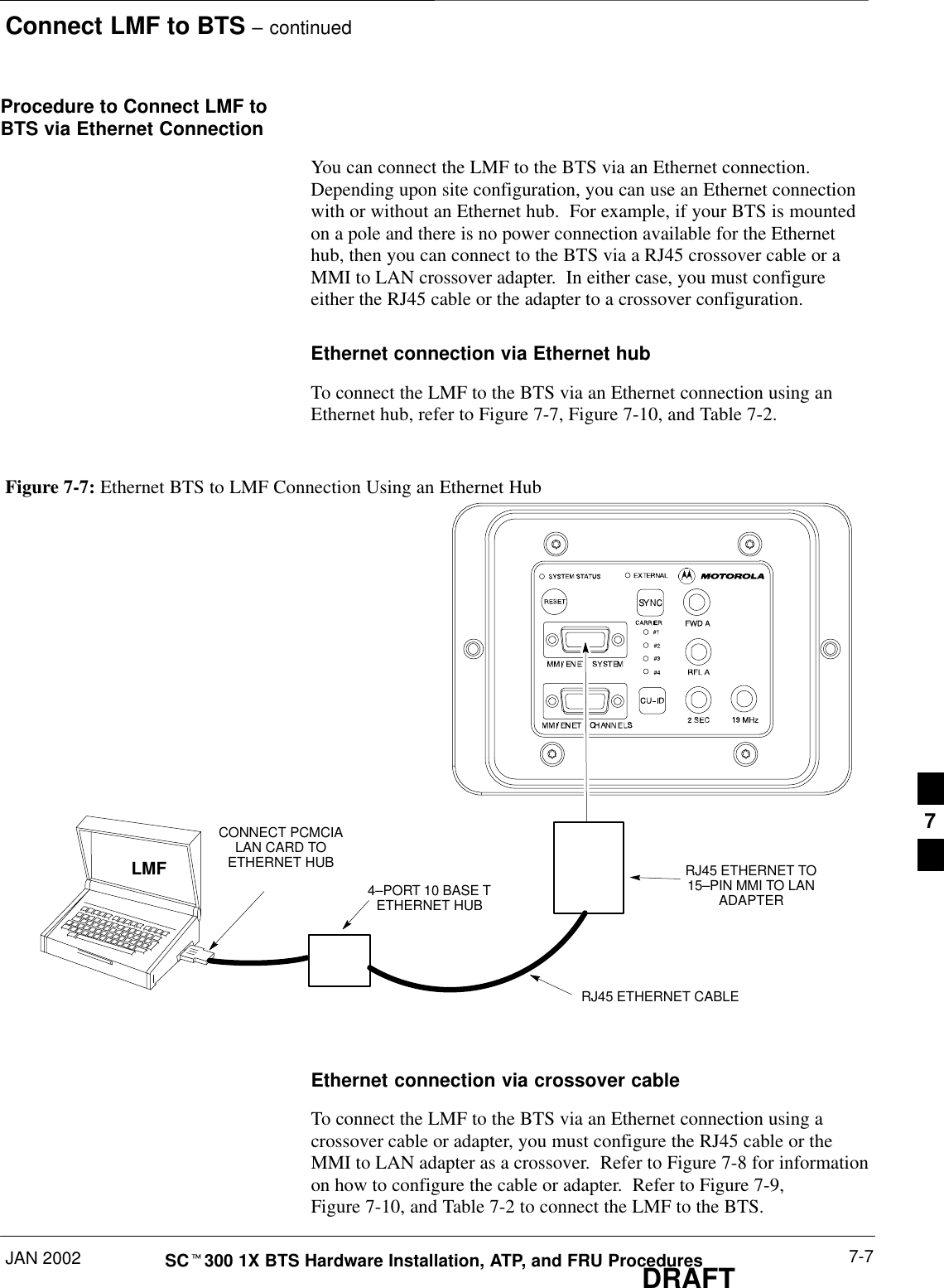
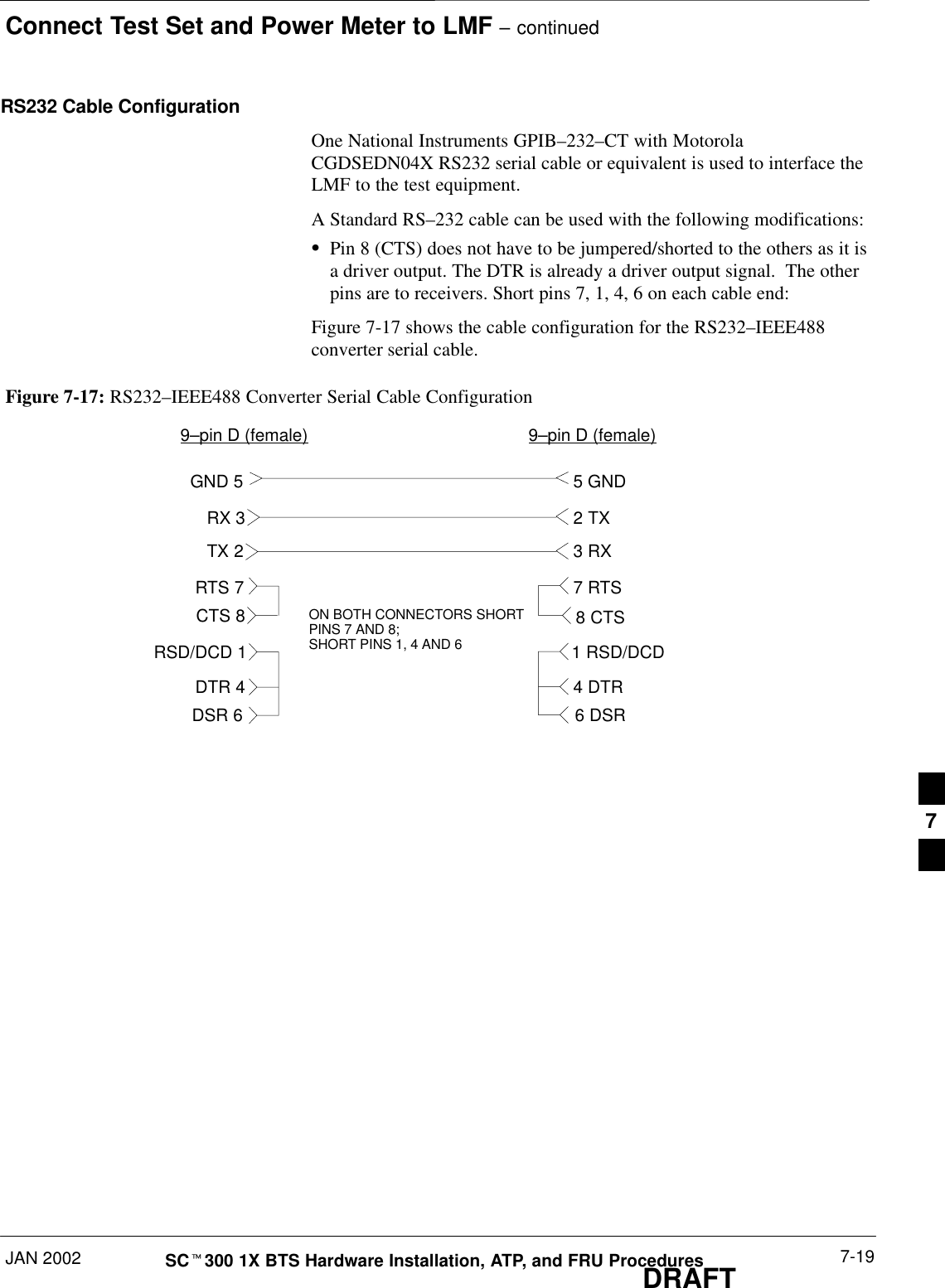
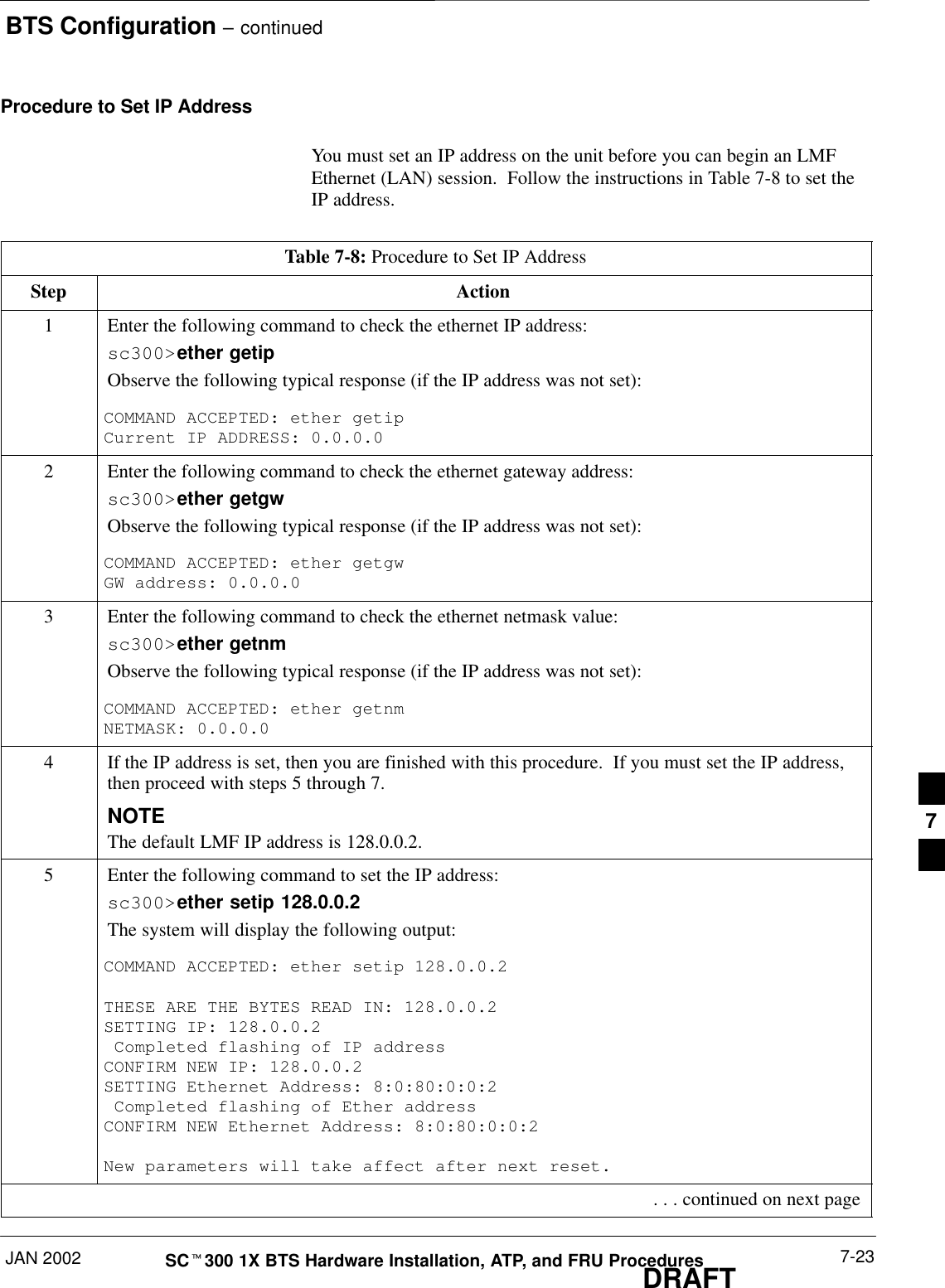
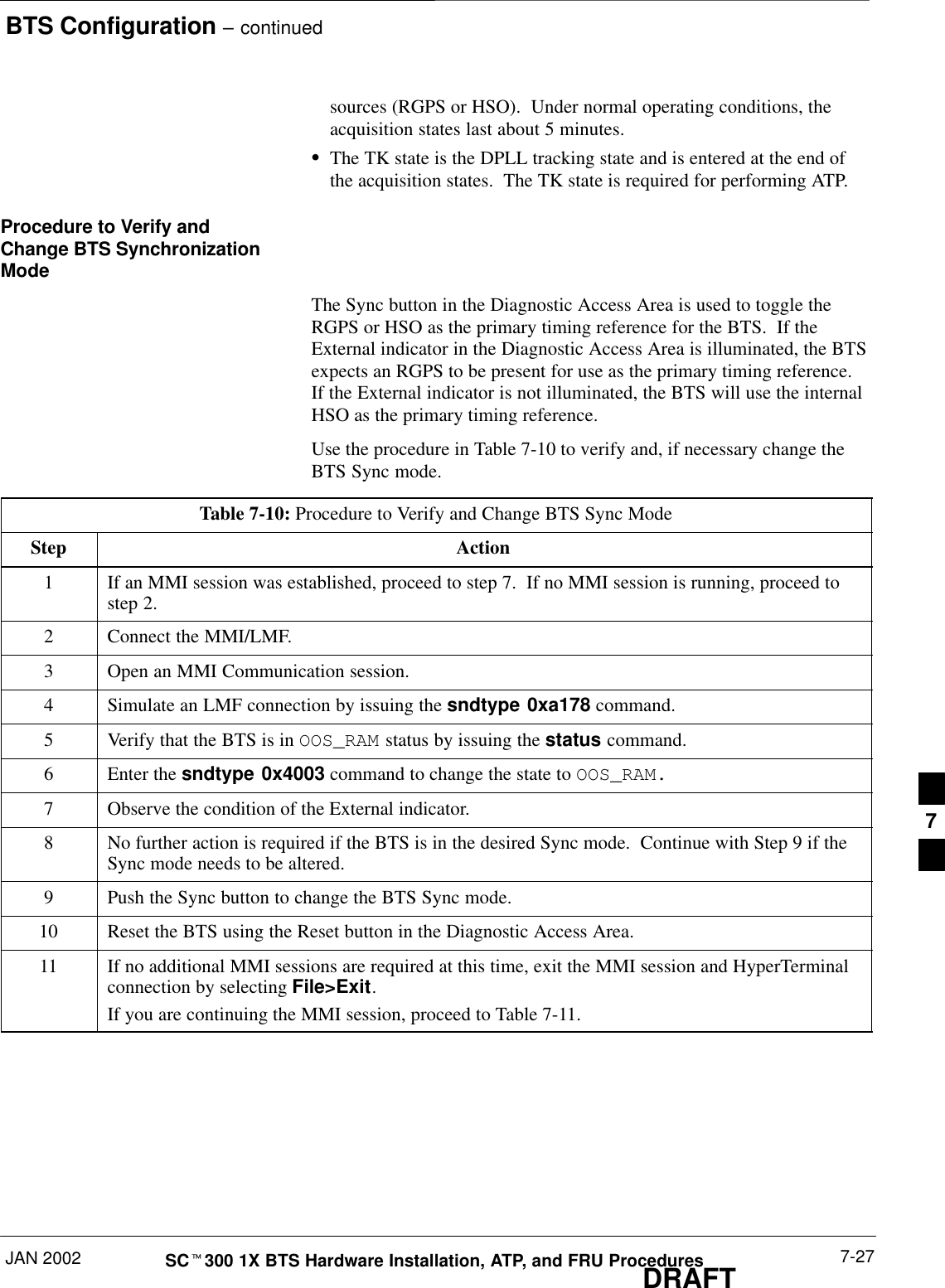
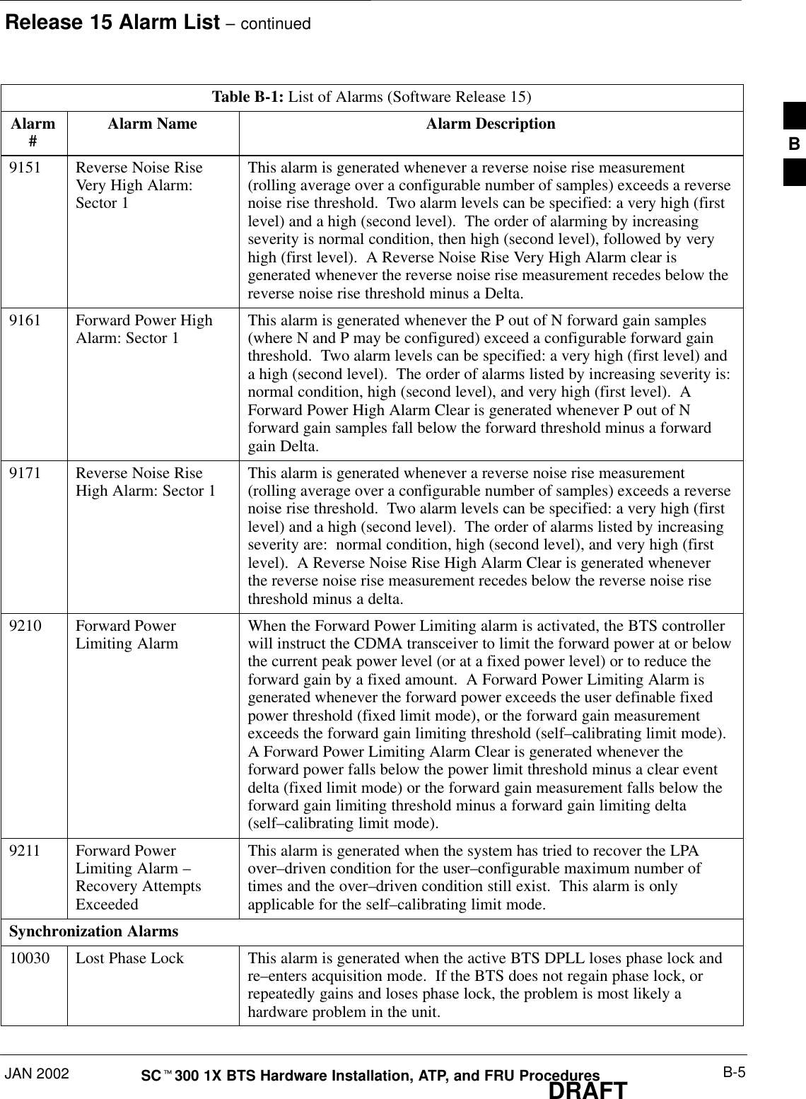
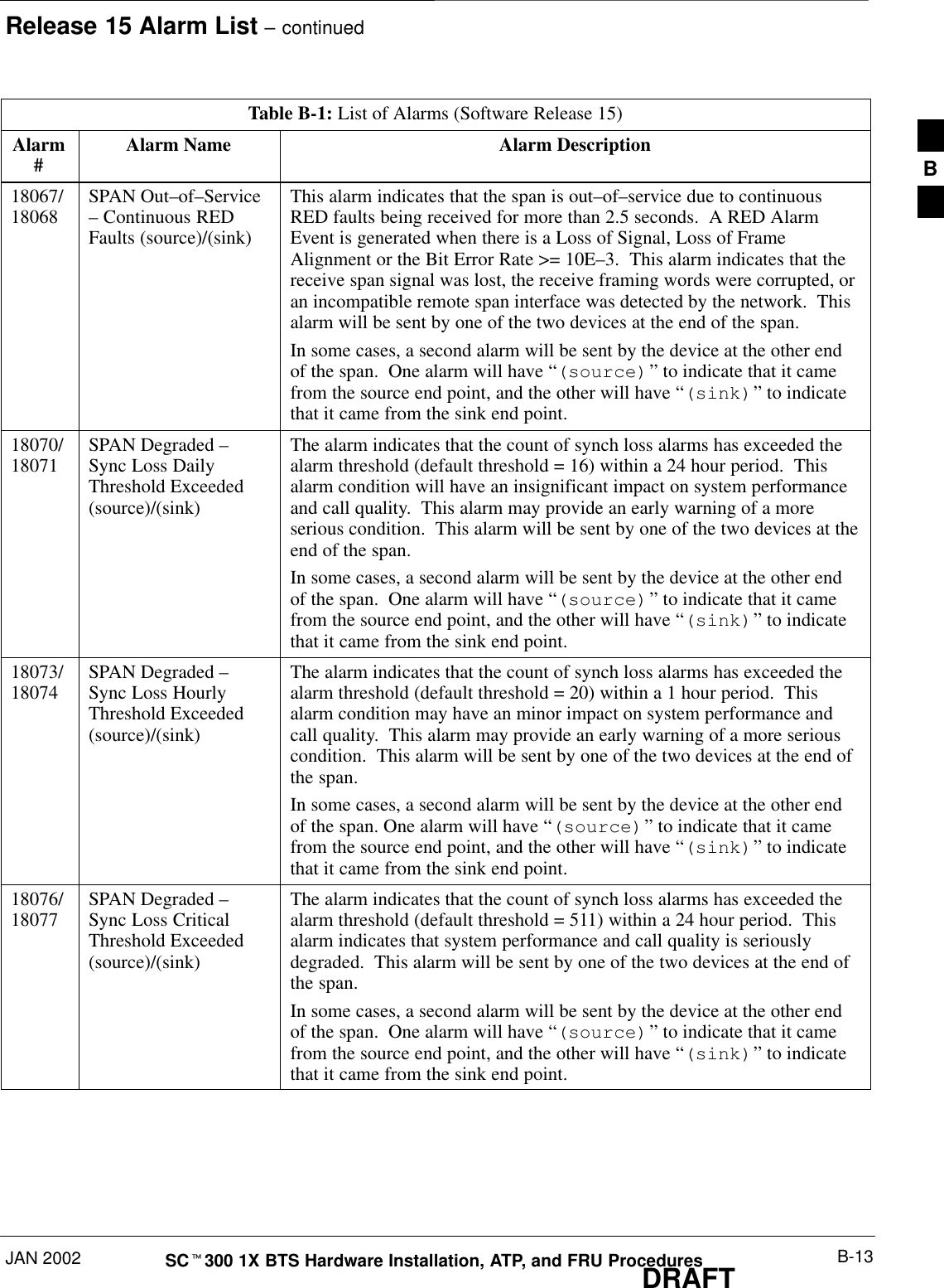
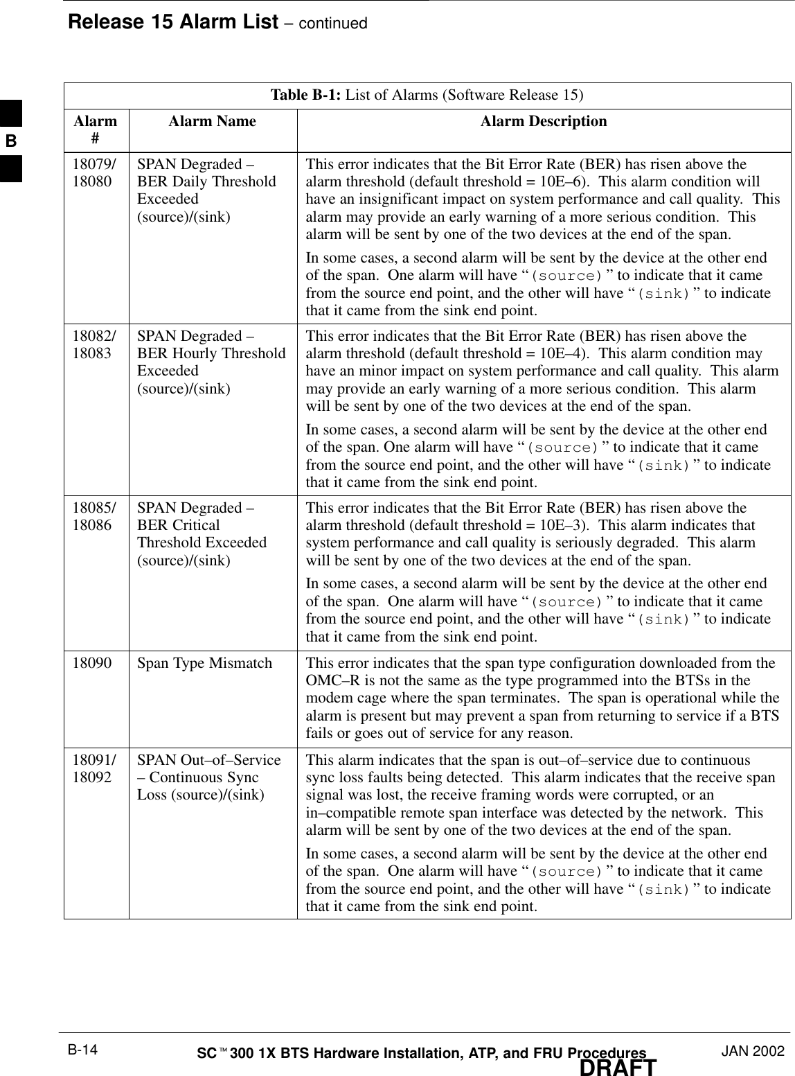
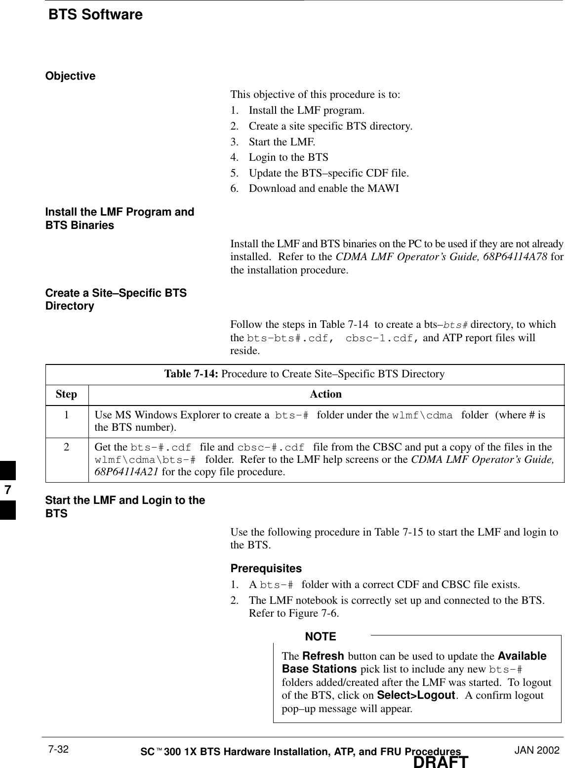
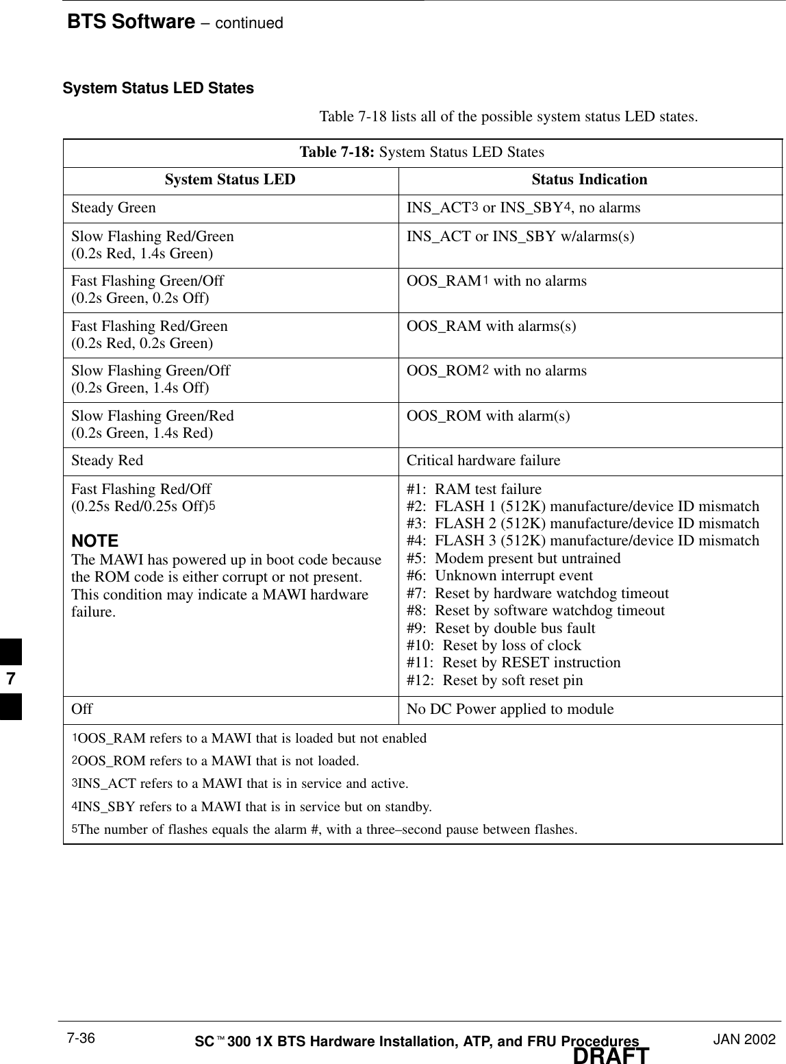
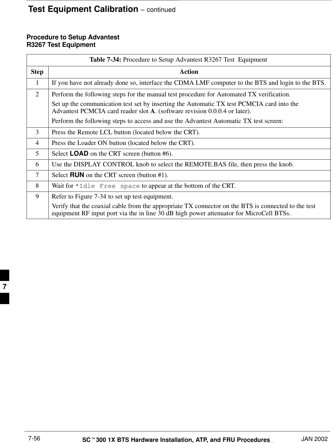
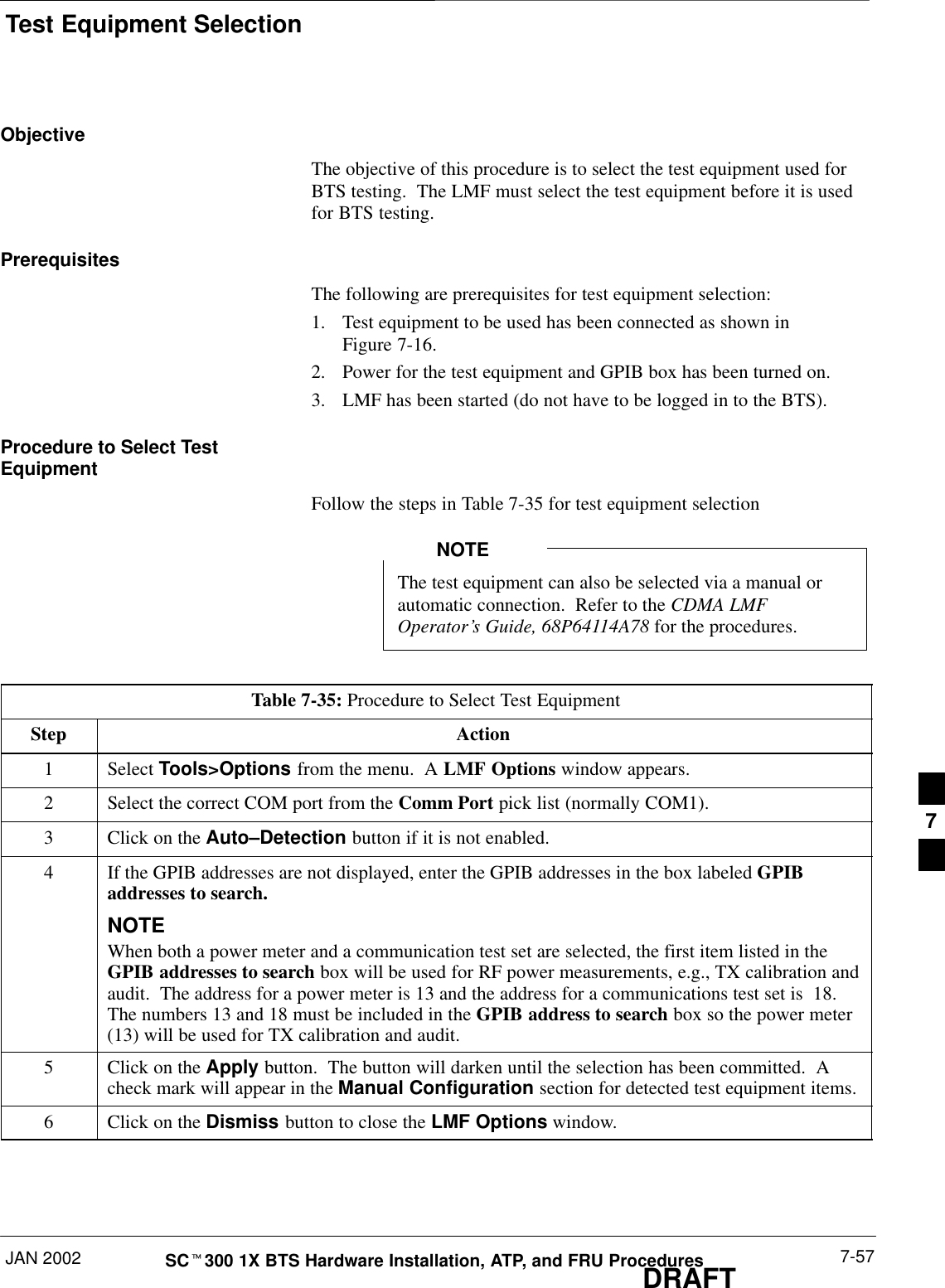
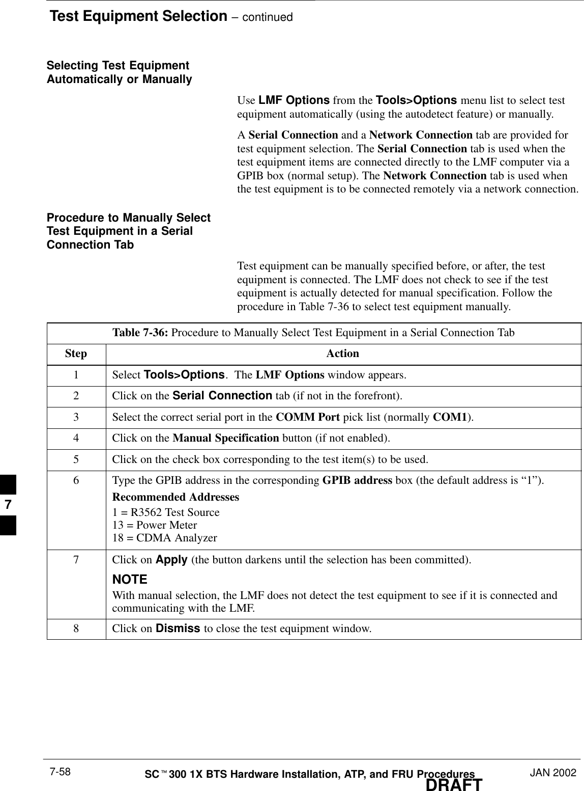
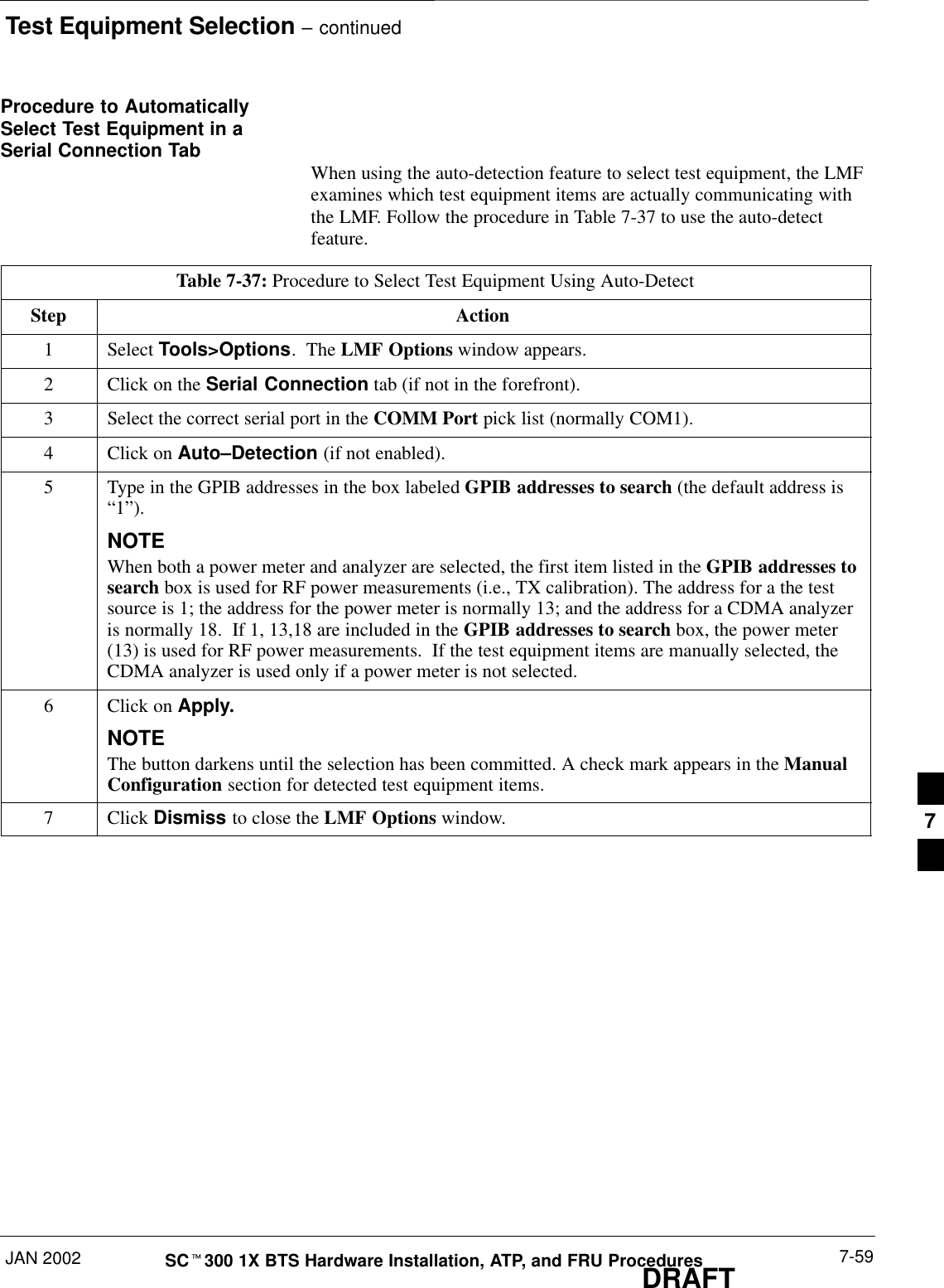
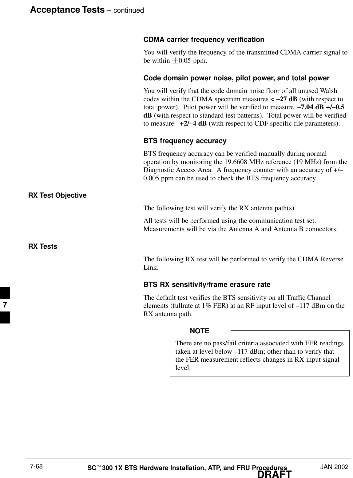
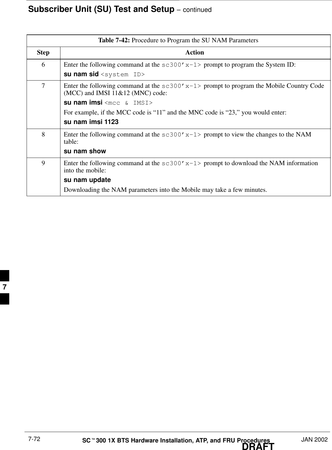
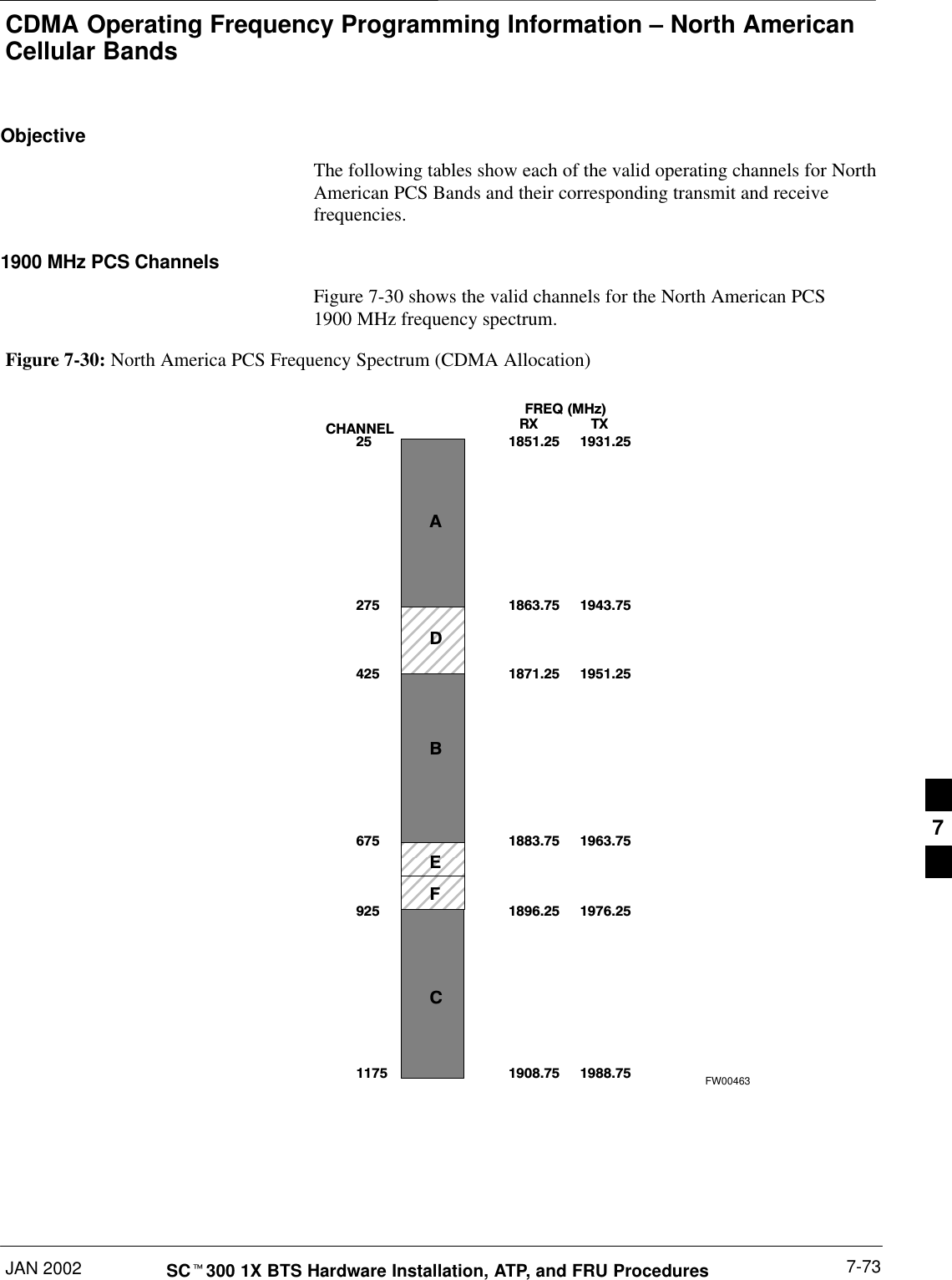
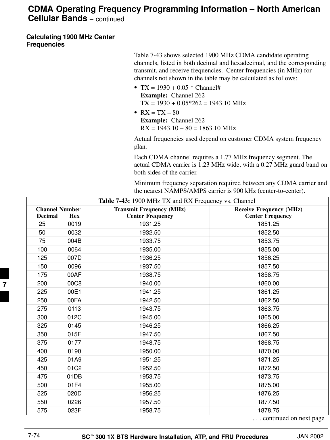
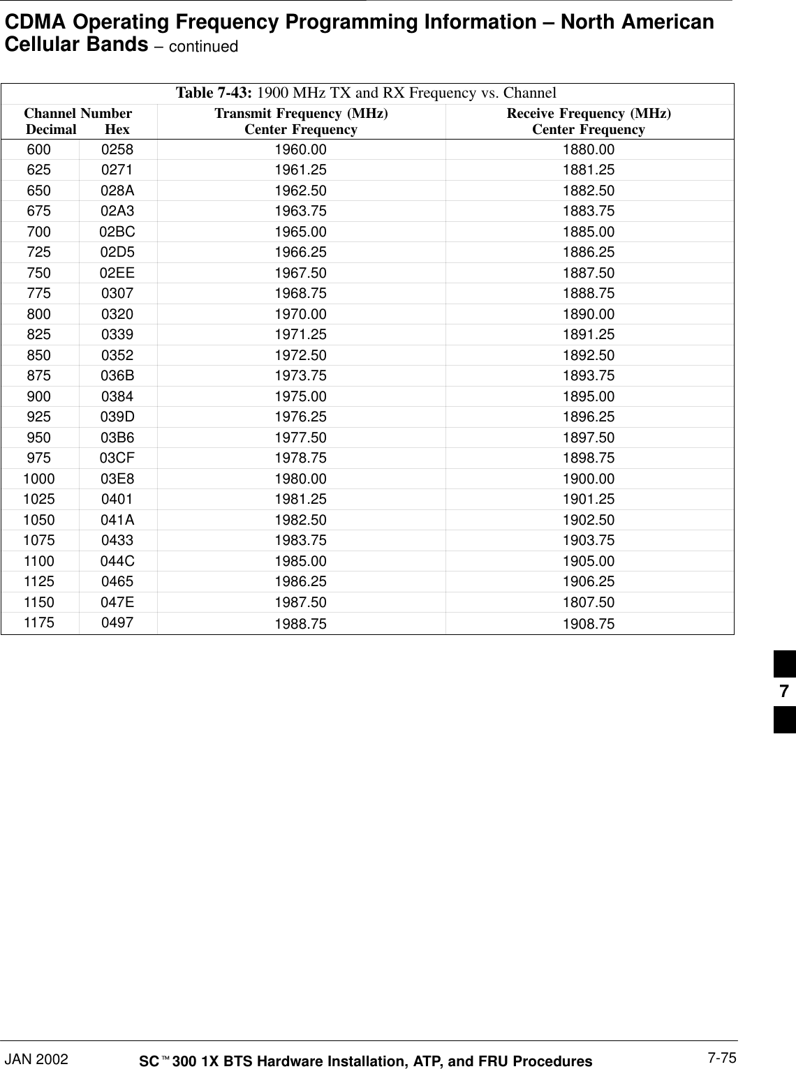
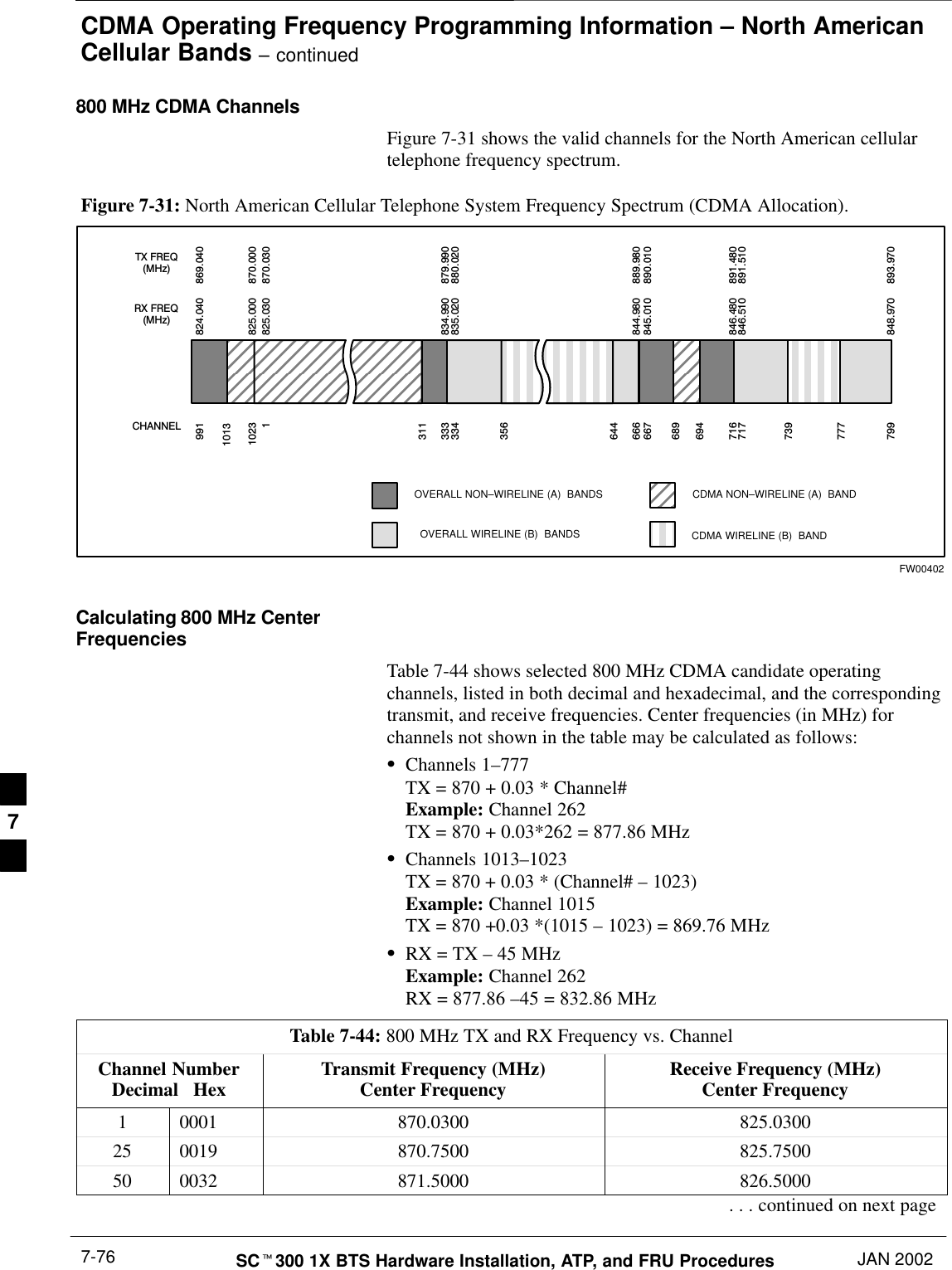
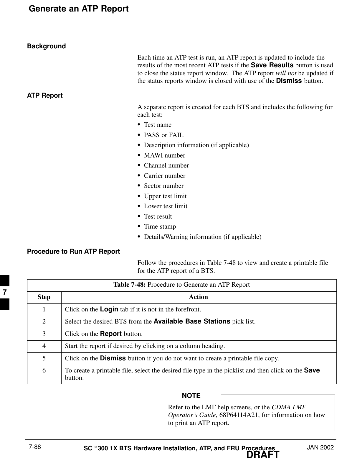
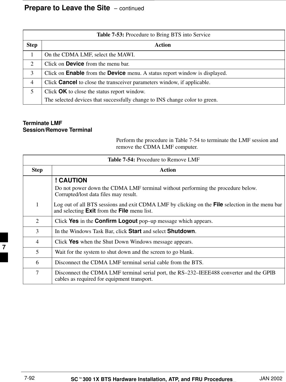
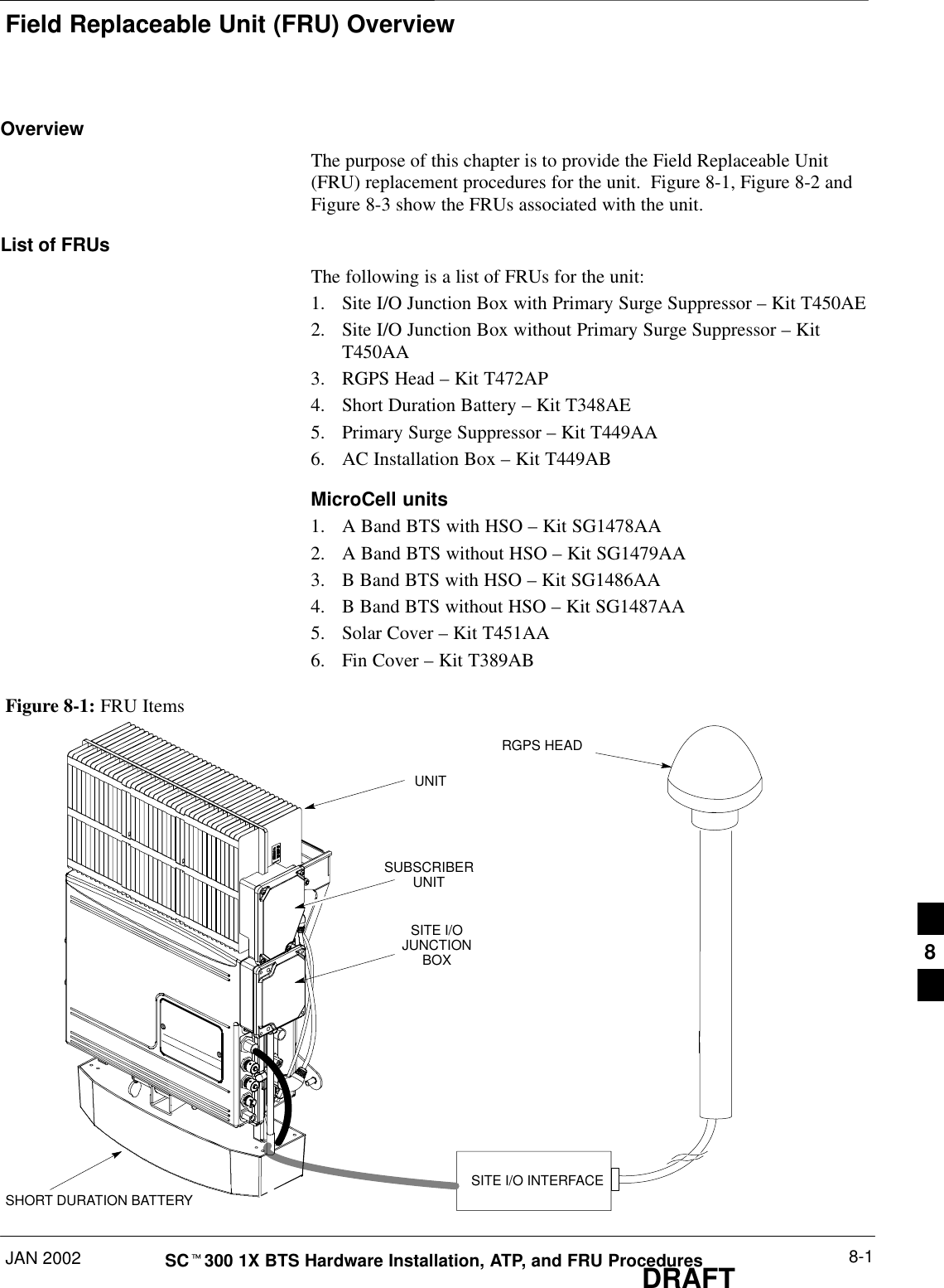
![BTS Configuration – continuedDRAFTSCt300 1X BTS Hardware Installation, ATP, and FRU Procedures JAN 20027-28Procedure to Verify DPLLTracking (RGPS/HSO)The DPLL within the BTS must be tracking either RGPS or HSO inorder to perform ATP. Use the procedure in Table 7-11 to verify DPLLtracking.Table 7-11: Procedure to Verify DPLL TrackingStep Action1If an MMI session was established, proceed to step 6. If no MMI session is running, proceed tostep 2.2Connect the MMI/LMF.3Open an MMI Communication session.4Simulate an LMF connection by issuing the sndtype 0xa178 command.5Verify that the BTS is in OOS_RAM status by issuing the status command.6If an RGPS is not present, go to Step 9.7Enter the gps_status command to display the current state of the RGPS. Observe the followingtypical response:gps_statusGPS Receiver Identification:Current GPS Time :8 03 1999 23:01:12Current GPS Receiver Status :8Number of Satellites Currently visible :11Number of Satellites Currently received :5Number of Satellites Currently tracked :5GPS Receiver Type :UTCurrent GPS Task State :GPS_TRACKCurrent Dilution of Precision (HDOP (2D)/antenna ok [0x01]): 0Chan: 0, SVID: 9, Mode: 8, RSSI: 44, Status: 0xaaChan: 1, SVID: 4, Mode: 8, RSSI: 46, Status: 0xaaChan: 2, SVID: 10, Mode: 8, RSSI: 44, Status: 0xaaChan: 3, SVID: 6, Mode: 8, RSSI: 41, Status: 0xaaChan: 4, SVID: 7, Mode: 8, RSSI: 43, Status: 0xaaChan: 5, SVID: 24, Mode: 8, RSSI: 47, Status: 0xaaChan: 6, SVID: 30, Mode: 8, RSSI: 45, Status: 0xaaChan: 7, SVID: 5, Mode: 8, RSSI: 48, Status: 0xaaCurrent Longitude: –350250952Current Latitude: 118244730Current Height: 240198The RGPS must have a Current GPS Task State of GPS_TRACK to proceed.NOTEGPS tracking times vary depending on location and installation. . . . continued on next page7](https://usermanual.wiki/Nokia-Solutions-and-Networks/T6CB1.Users-Manual-3-of-3/User-Guide-220230-Page-32.png)
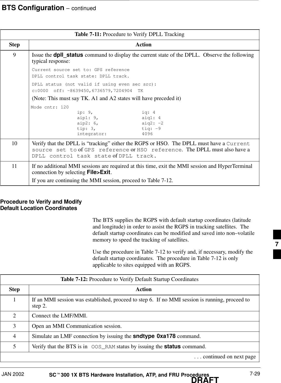
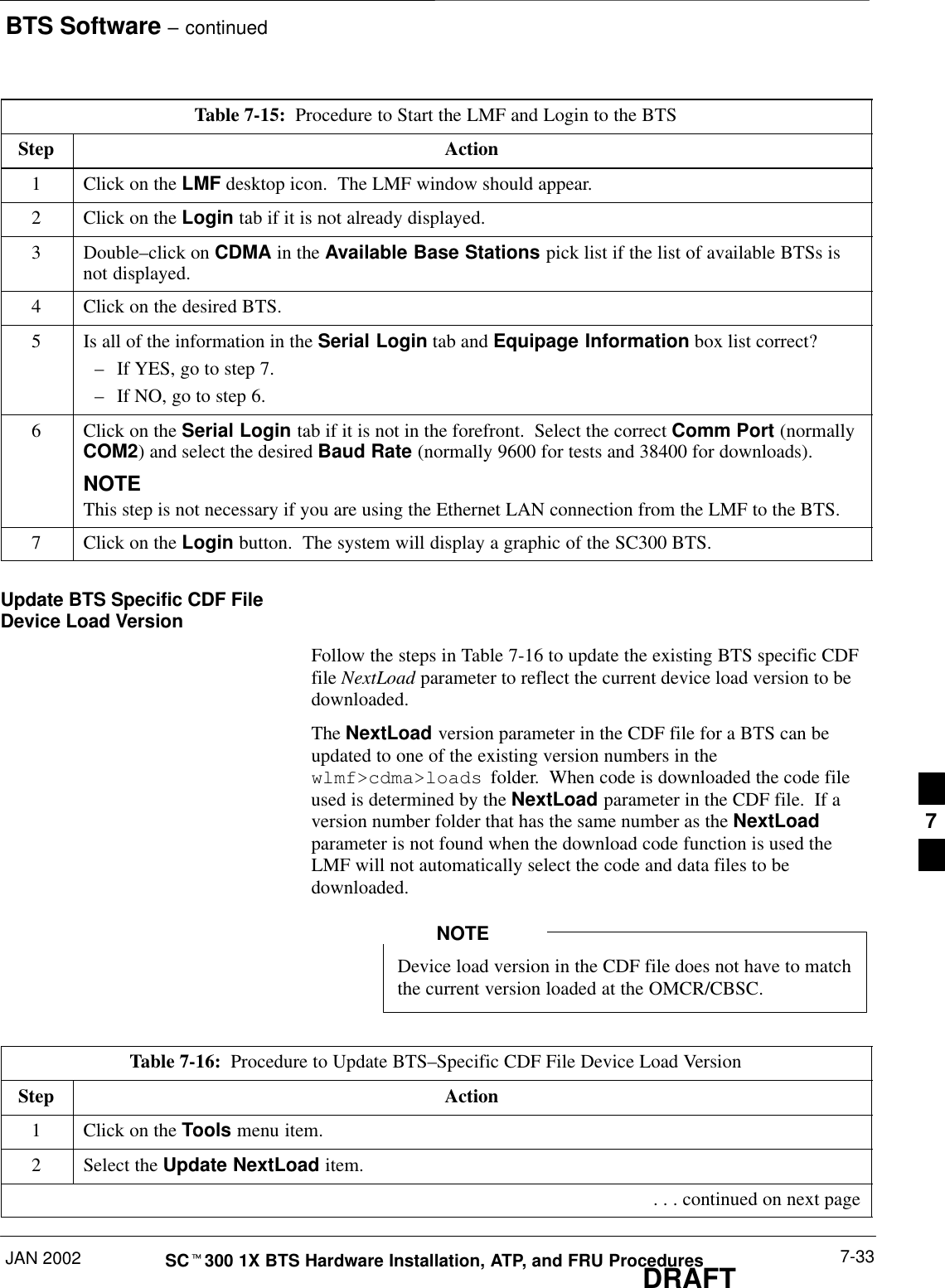
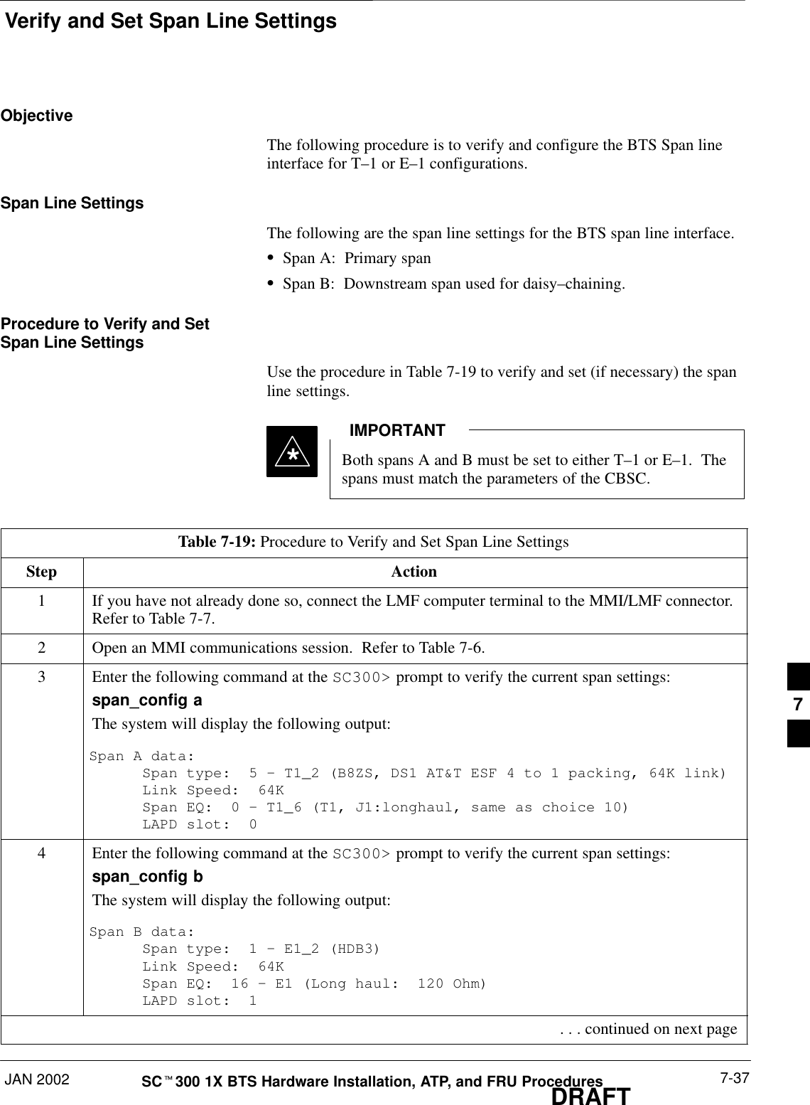
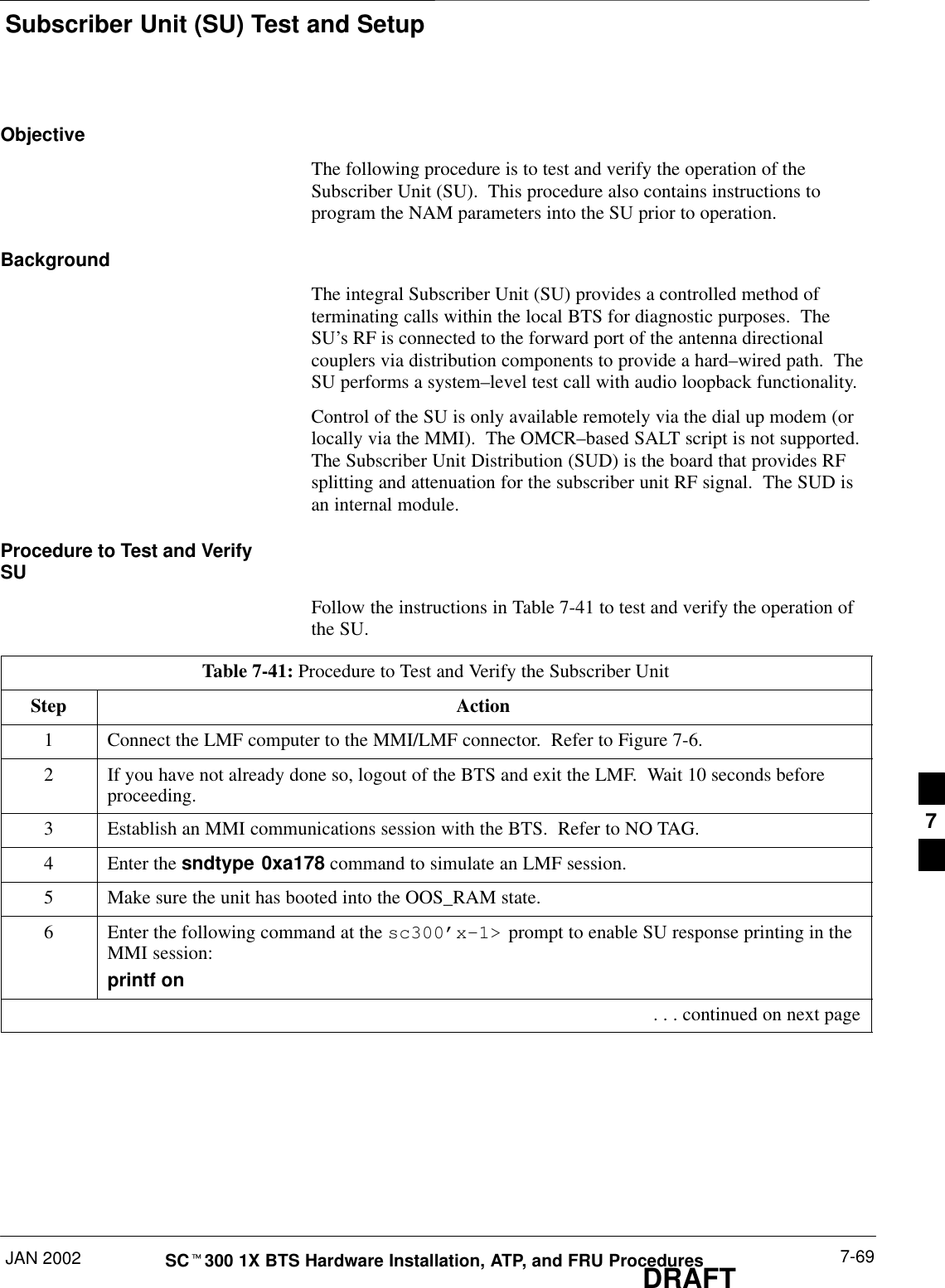
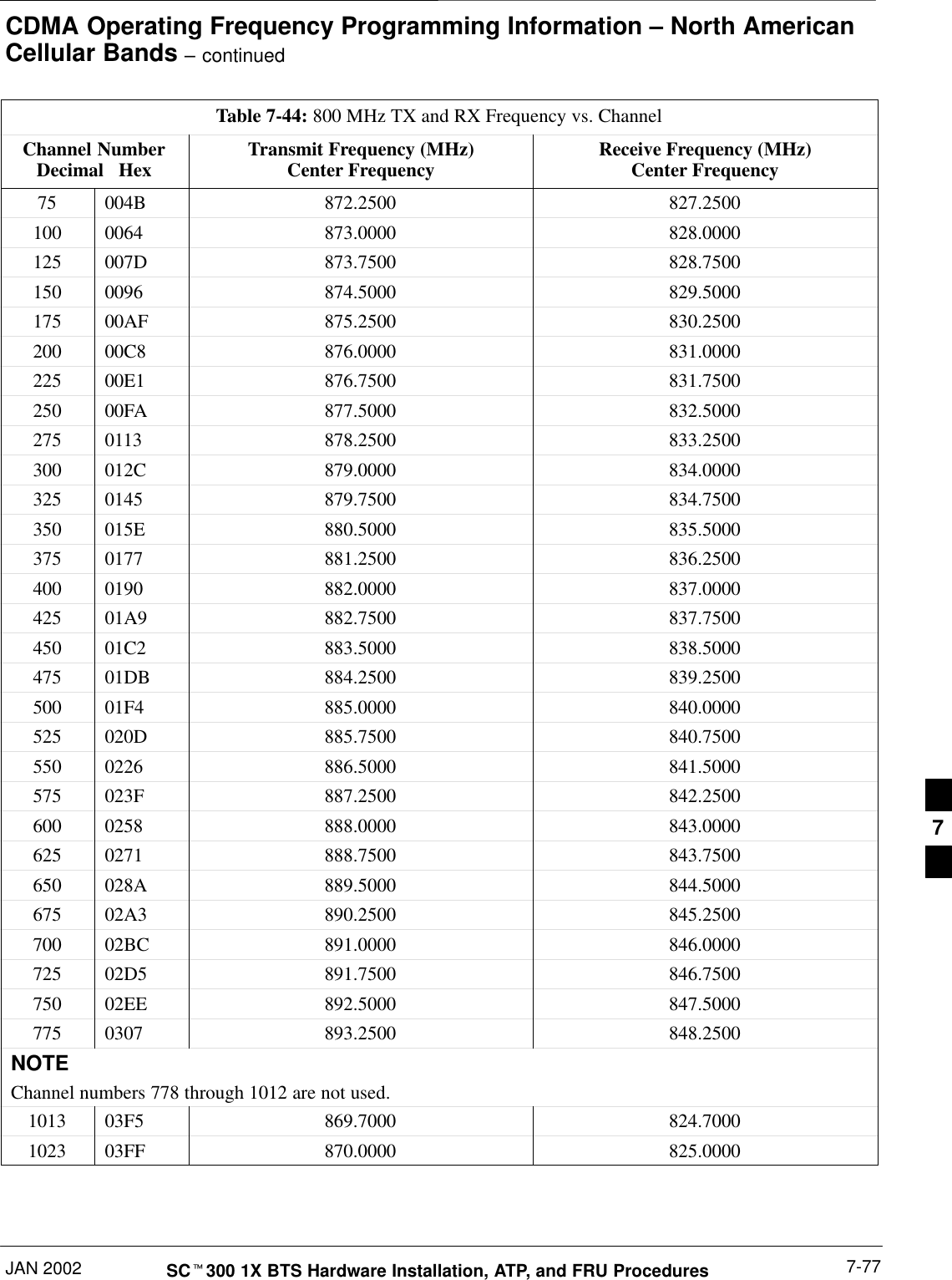
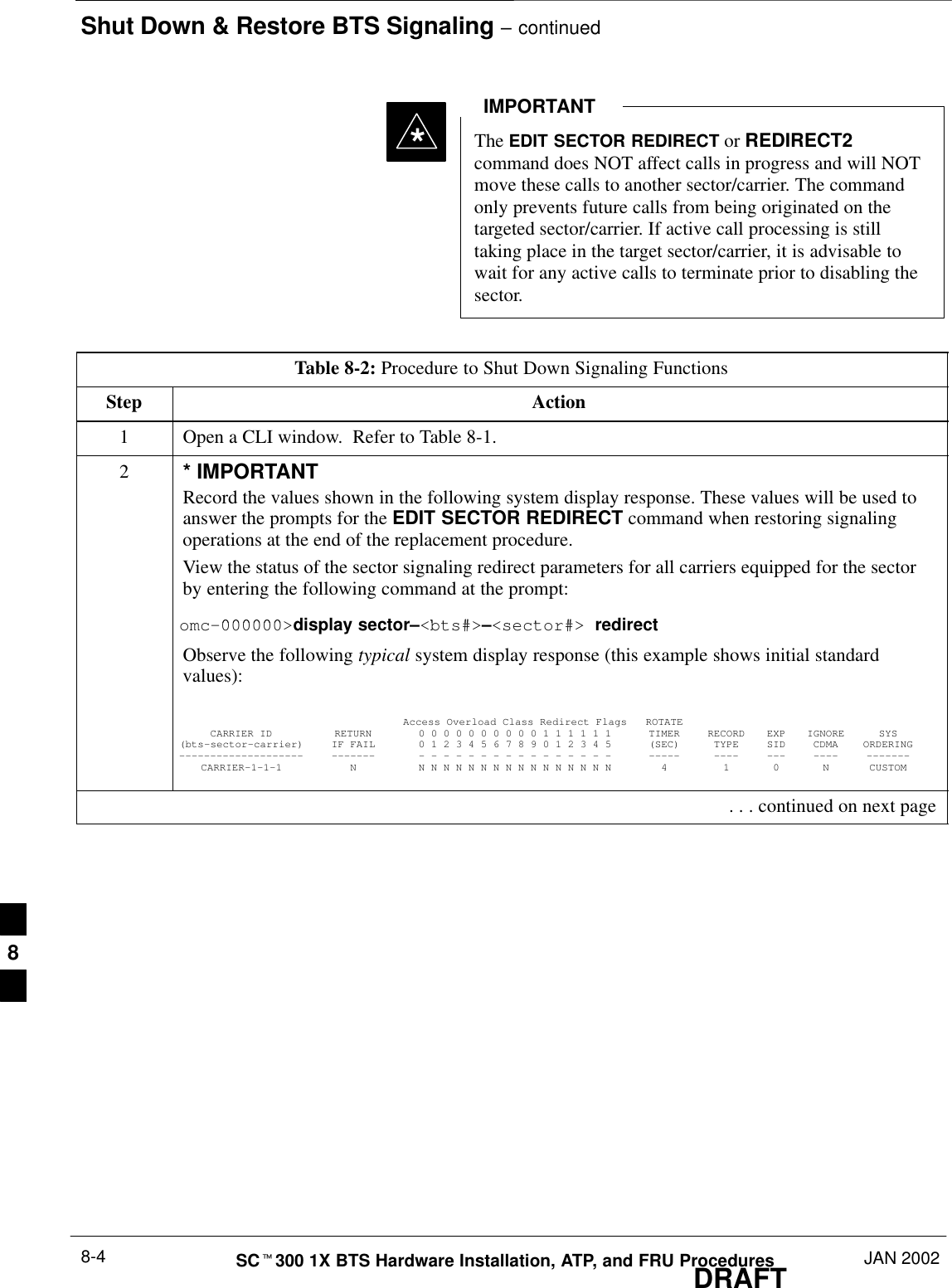
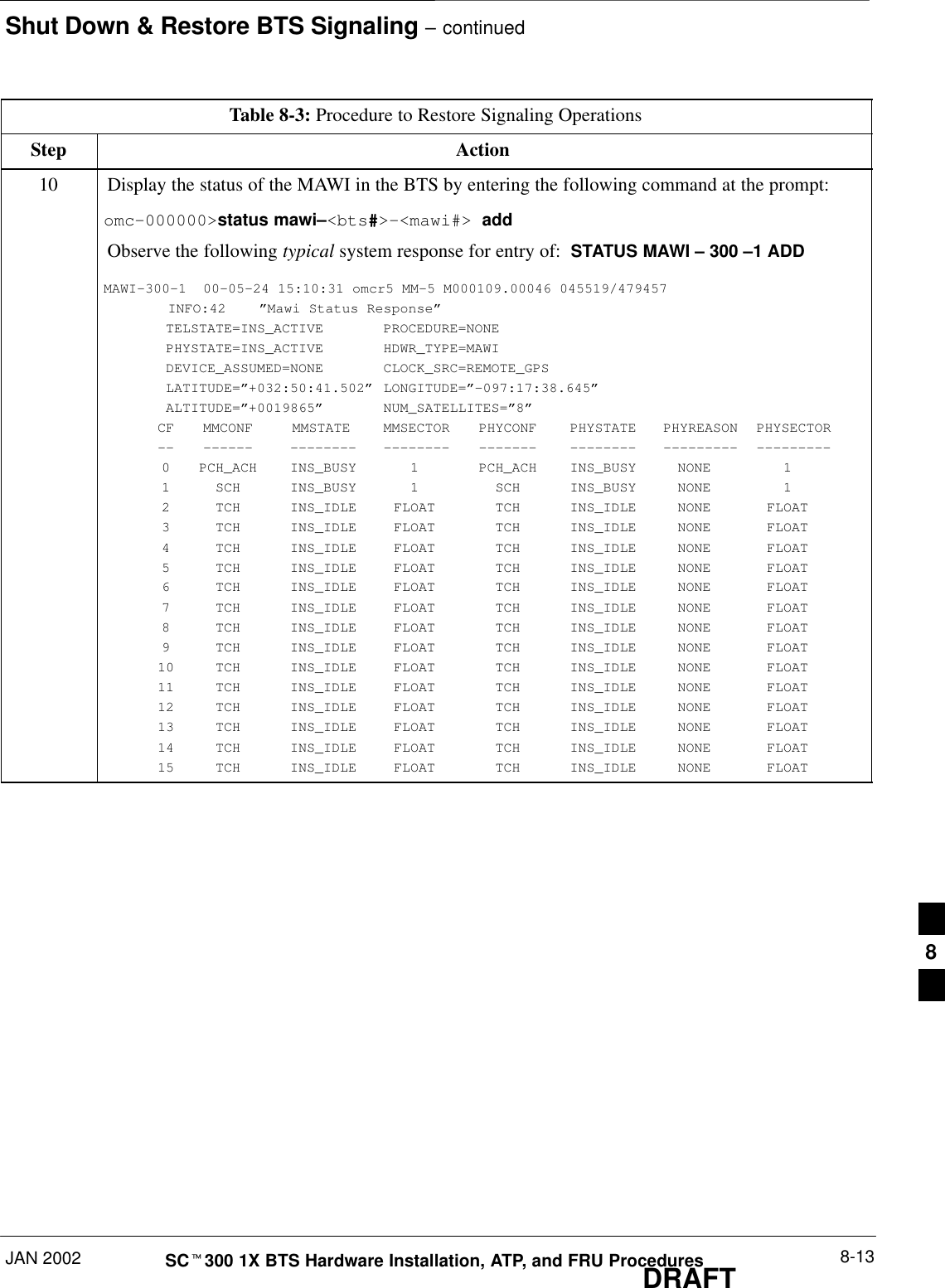
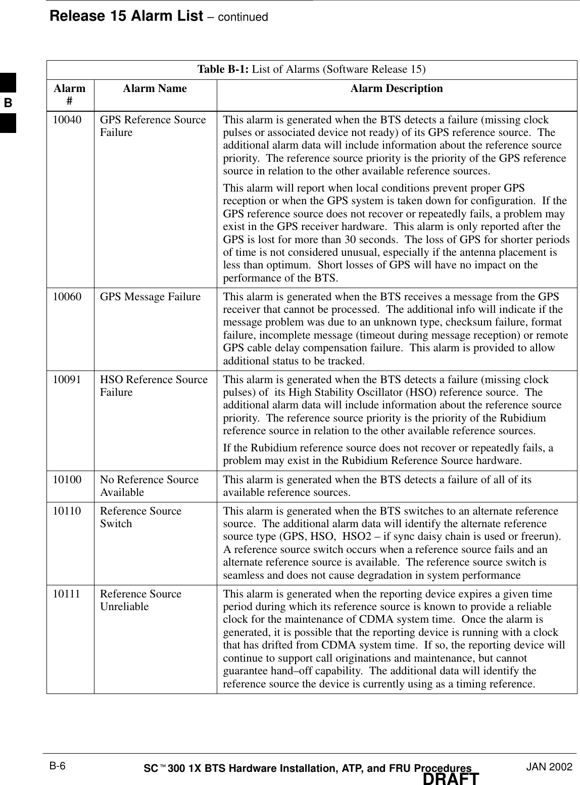
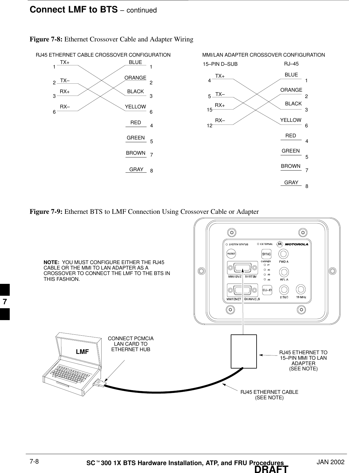
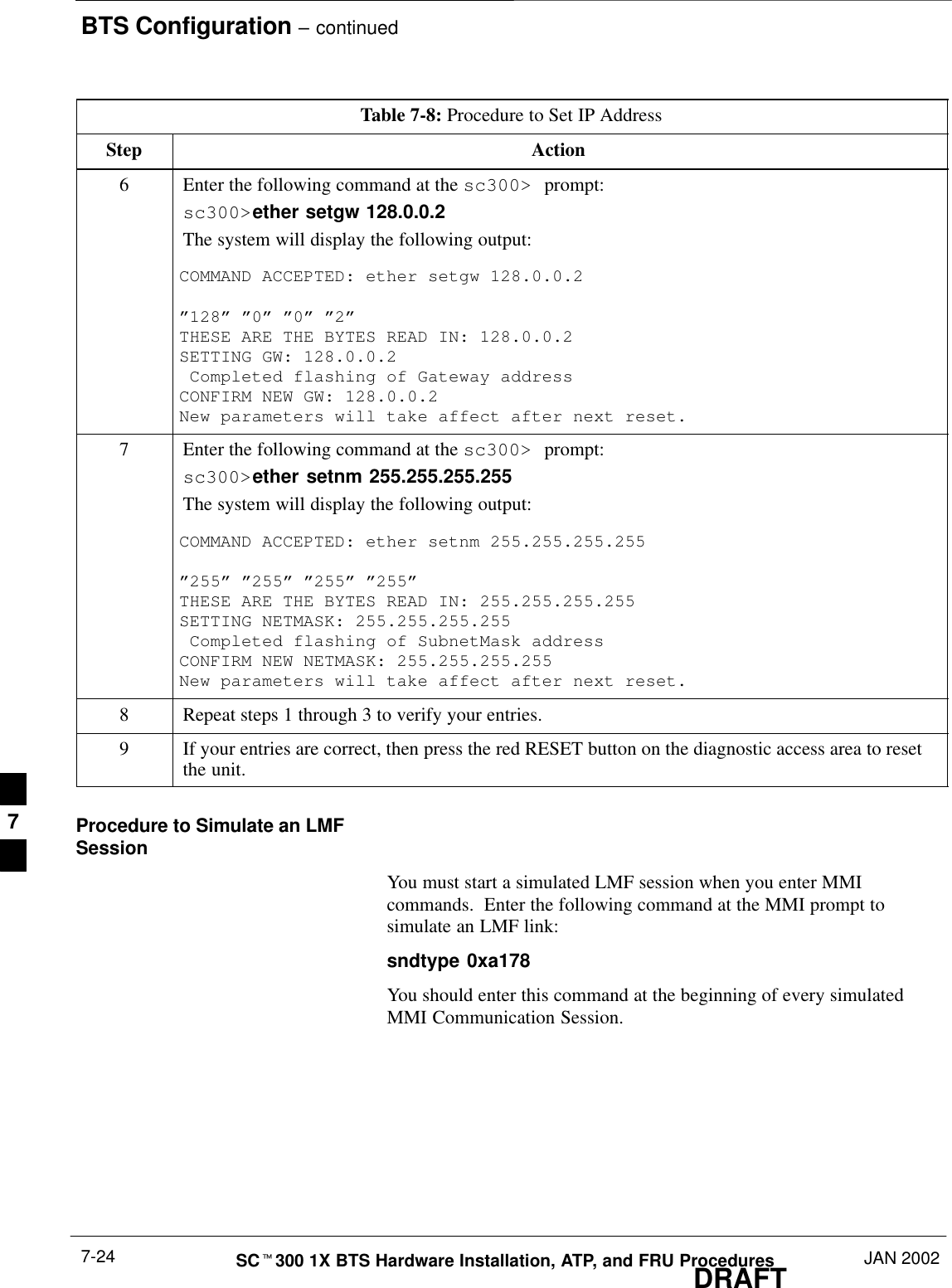
![Shut Down & Restore BTS Signaling – continuedJAN 2002 8-5SCt300 1X BTS Hardware Installation, ATP, and FRU ProceduresDRAFTTable 8-2: Procedure to Shut Down Signaling FunctionsStep Action3NOTEThis step edits the redirect parameters so that the Global Service Redirect Message broadcast onthe paging channel redirects all subscribers away from the sector with the failed equipment andonto a different system.Enter the following command at the prompt:omc–000000>edit sector–<bts#>–<sector#> redirect !The system will prompt you to enter each command parameter value one at a time. Answer theprompts in the following order:<accolc0> enter Y, <accolc1> enter Y, ... <accolc15> enter YAll Access Overload Classes must be set to Y (yes) to ensure that all subscribers are redirected.<returniffail> , enter NMust be set to no to ensure that subscribers do not return if redirect is unsuccessful.<recordtype> , enter 1 or 2 A value of 2 will invoke REDIRECT2 which is used to redirect subscribers to a CDMA channelat a neighbor site. A value of 1 redirects subscribers to an 800 MHz analog site. This exampleuses 2.<expe tedsid><expectedsid> , enter 13 Use the Area ID the subscriber units should expect to find on the system they are being redirectedto. This example uses 13.<ignorecdma> , enter Y<sysordering> , enter custom The system acquisition ordering value tells the mobiles the order to use when attempting to obtainservice on the different analog systems. The valid values are: custom – use custom systemselection (default selection); aonly – try the A system only; bonly – use the B system only;afirst – try the A system first. If unsuccessful, enter bfirst to try the B system first. Ifunsuccessful, enter aorb to try the A or B. If unsuccessful, enter custom to try the alternativesystem.<rotatetimer> , enter 4 Call processing continuously rotates, circular right–shifts, the Y/N values of Access OverloadClass Redirect Flags 0 to 9. Values are shifted one flag at the end of the timer period; then timerre–starts. Valid values are 0–255; 4 is default.The system will display the command that will be sent. Verify the command syntax.omc–000000>Accept [yes/no]?Enter Y to accept the command. . . . continued on next page8](https://usermanual.wiki/Nokia-Solutions-and-Networks/T6CB1.Users-Manual-3-of-3/User-Guide-220230-Page-105.png)
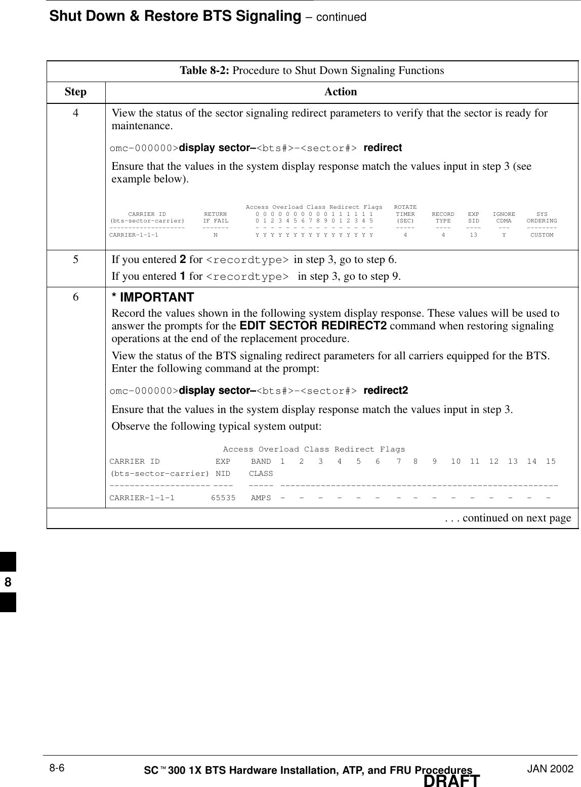
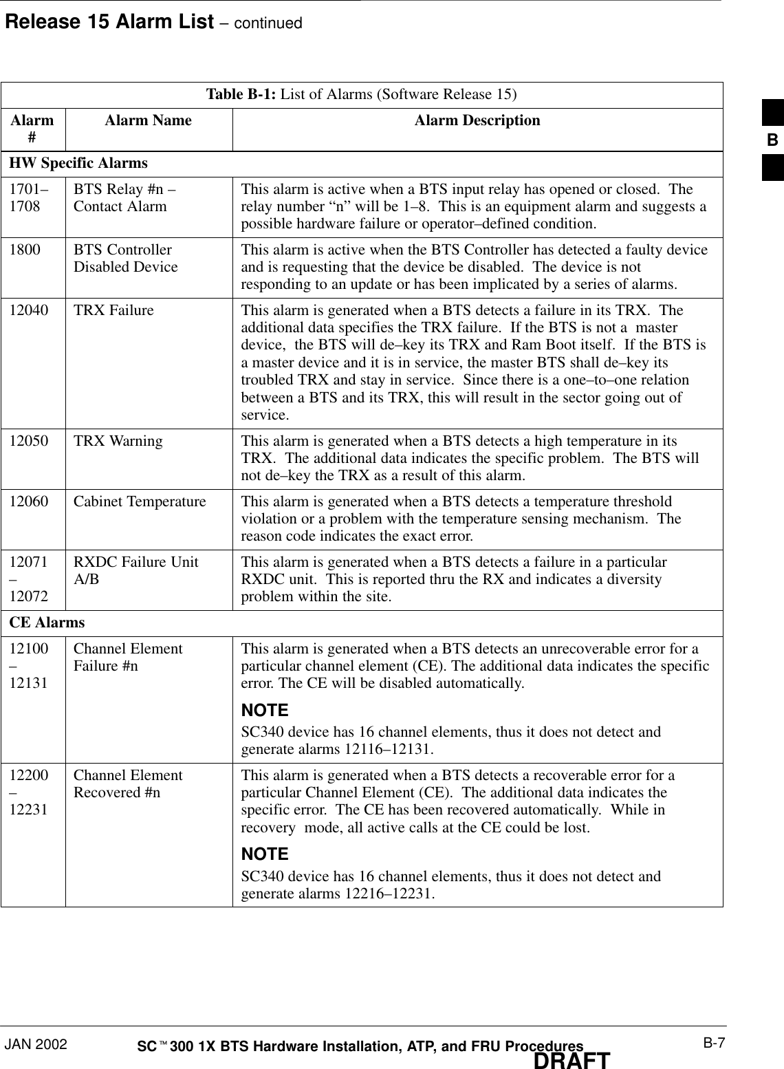
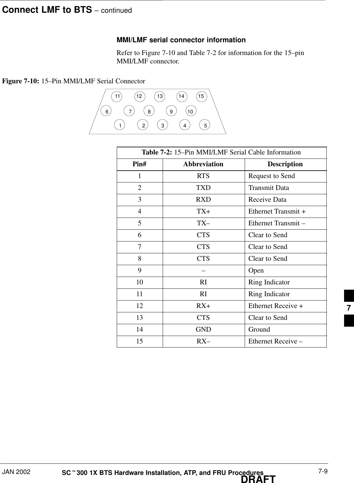
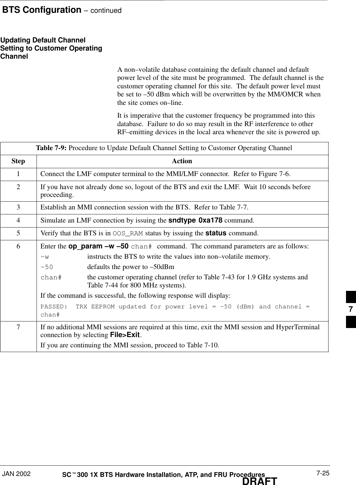
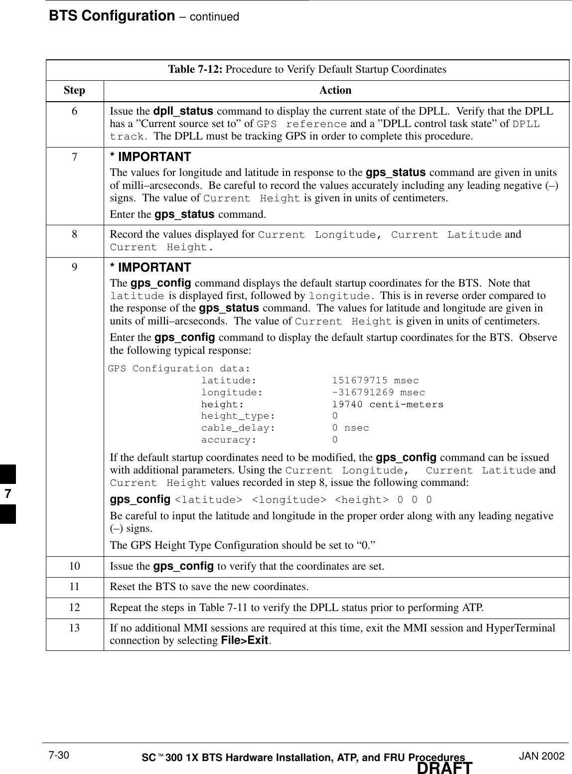
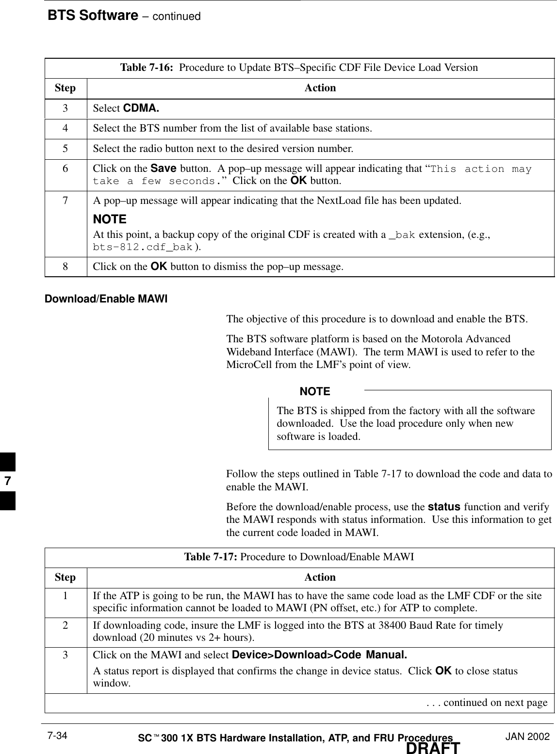
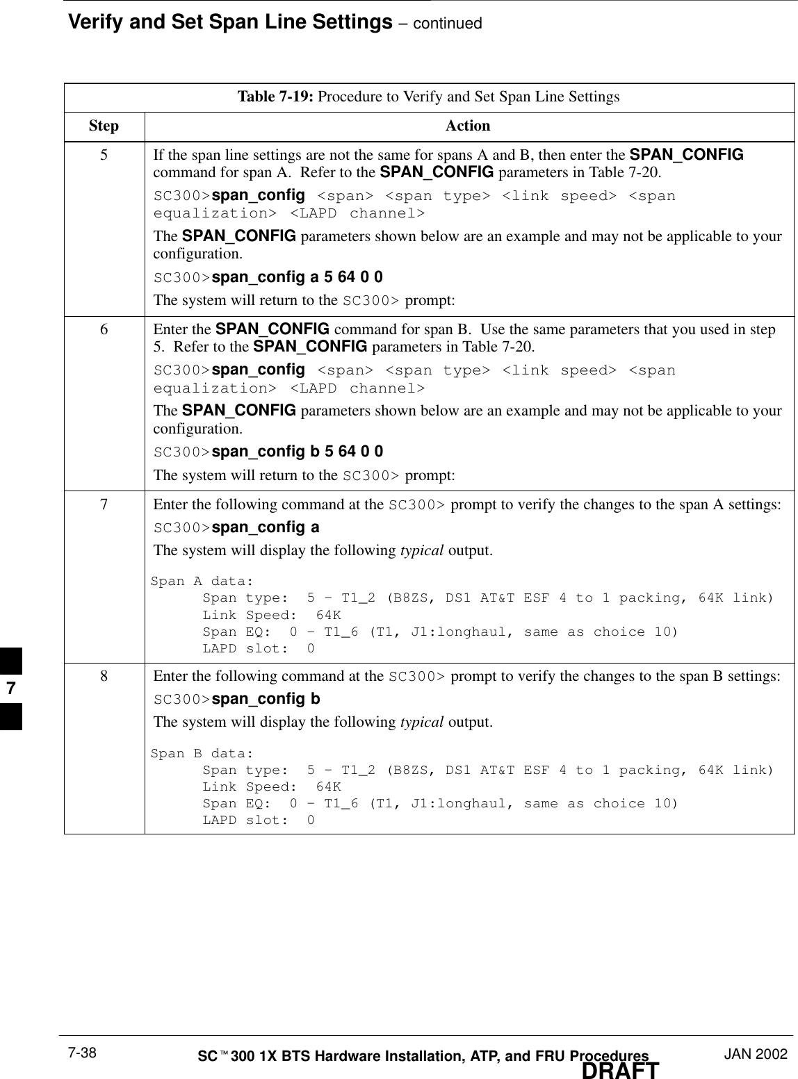
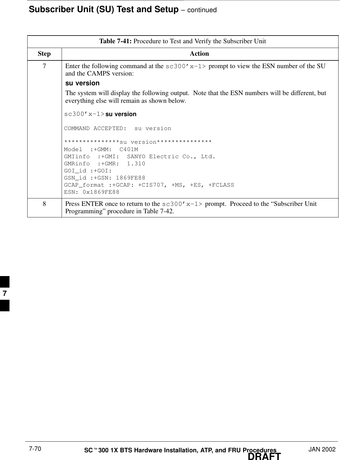
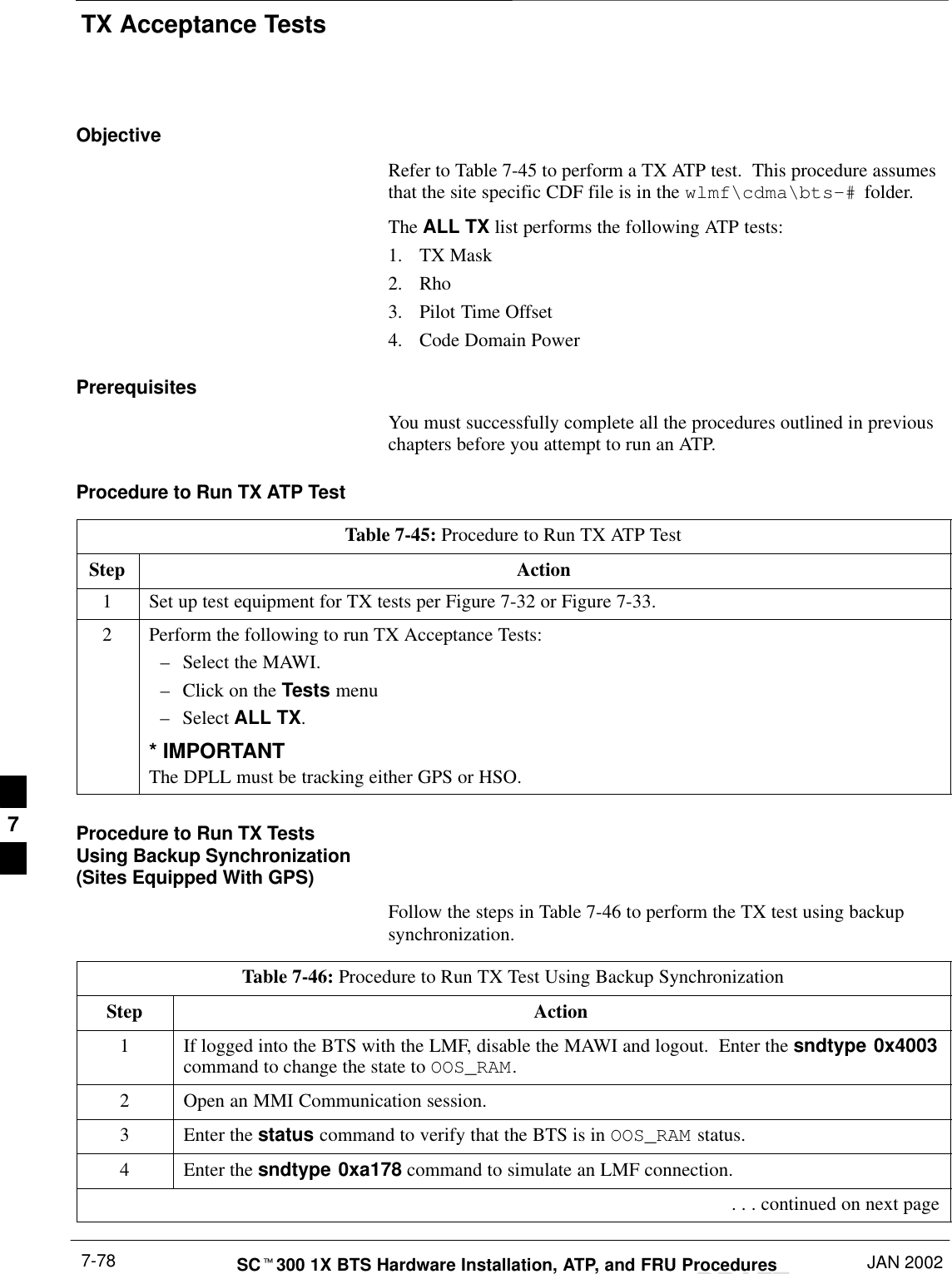
![Shut Down & Restore BTS Signaling – continuedJAN 2002 8-7SCt300 1X BTS Hardware Installation, ATP, and FRU ProceduresDRAFTTable 8-2: Procedure to Shut Down Signaling FunctionsStep Action7NOTEThis step edits the REDIRECT2 parameters so that the Global Service Redirect Messagebroadcast on the paging channel redirects all subscribers away from the BTS with the failedequipment and onto a CDMA channel at a neighbor site.Enter the following command at the prompt:omc–000000>edit sector–<bts#>redirect2!The system prompts you to enter each command parameter value one at a time. Answer theprompts in the following order:expecting an integer number (from 0 to 65535)<EXPNID= ?>Use the Network ID the subscriber units should expect to find on the system they are beingredirected to. This example uses 555.redirected to. This example uses 555.expecting an integer number (from 0 to 2047)<CHAN1=?>, <CHAN2=?>...<CHAN15=?>A list of CDMA channels for neighbor sites that the subscriber units can use for redirection. Thisexample uses 200, 350, 400, 725, 75, 175, 100, 575, and 950.expecting an enumerated value:CDMA1900 CDMA800 CDMA900 JAPANCDMA<BANDCLASS=?>Use CDMA1900 for 1.9 GHz systems and CDMA800 for 800 MHz systems. This example usesCDMA1900.The system displays the command to be sent. Verify the command syntax.omc–000000>Accept [yes/no]?Enter Y to accept the command or N to go back and enter the correct value(s).8View the status of the BTS signalling REDIRECT2 parameters to verify that the BTS is ready formaintenance.omc–000000>display sector–<bts#> redirect2Make sure that the values in the system display response match the values input in step 7 (seeexample below):Access Overload Class Redirect Flags ROTATECARRIER ID RETURN 0 0 0 0 0 0 0 0 0 0 1 1 1 1 1 1 TIMER RECORD EXP IGNORE SYS(bts–sector–carrier) IF FAIL 0 1 2 3 4 5 6 7 8 9 0 1 2 3 4 5 (SEC) TYPE SID CDMA ORDERING–––––––––––––––––––– ––––––– – – – – – – – – – – – – – – – – ––––– –––– –––– ––– ––––––––CARRIER–1–1–1 N Y Y Y Y Y Y Y Y Y Y Y Y Y Y Y Y 4 4 13 Y CUSTOM . . . continued on next page8](https://usermanual.wiki/Nokia-Solutions-and-Networks/T6CB1.Users-Manual-3-of-3/User-Guide-220230-Page-107.png)
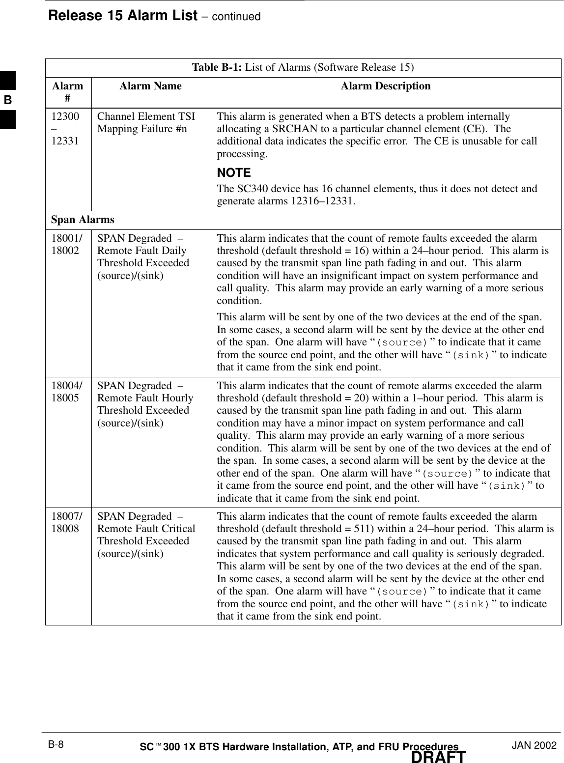
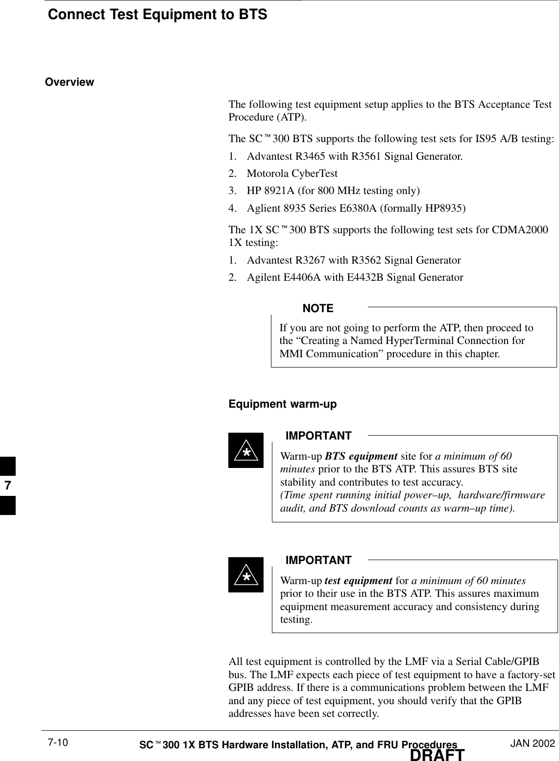
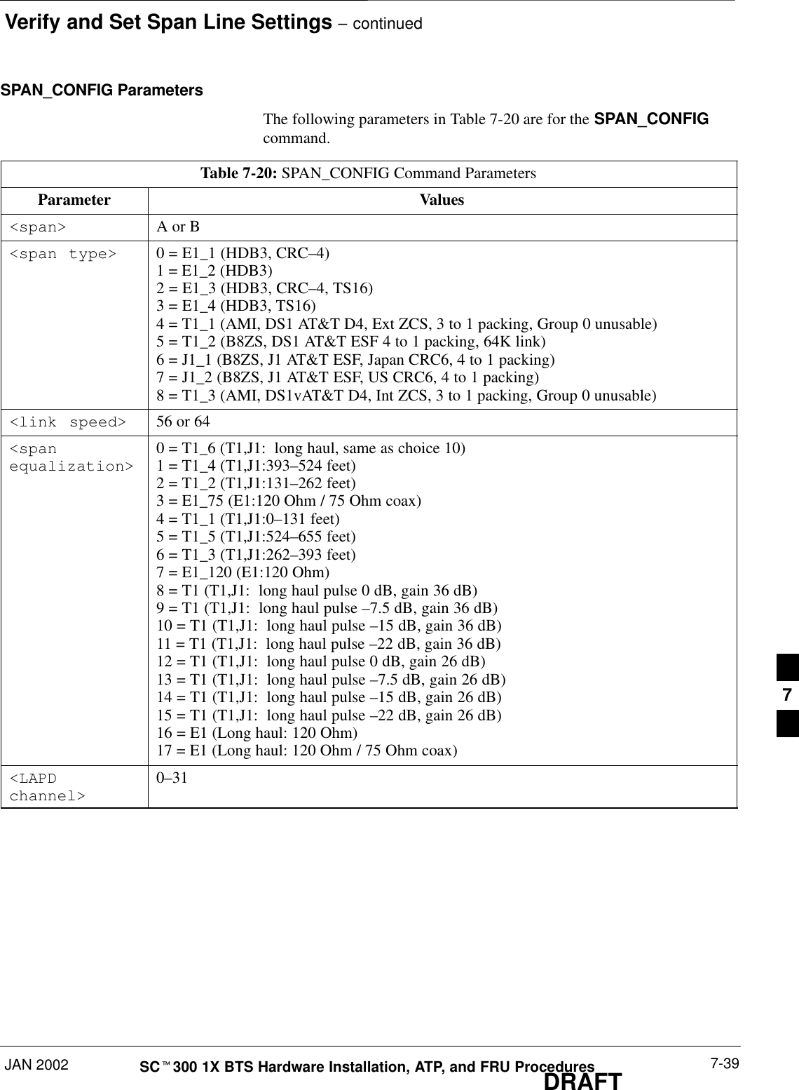
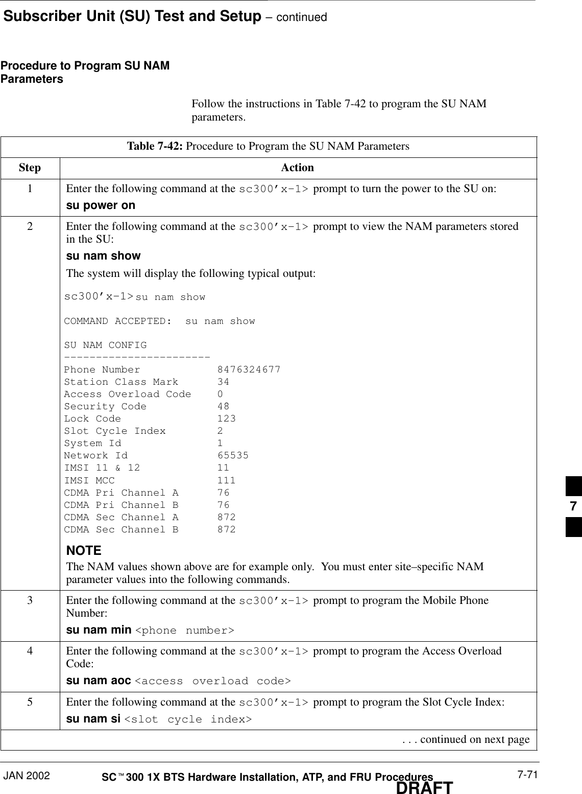
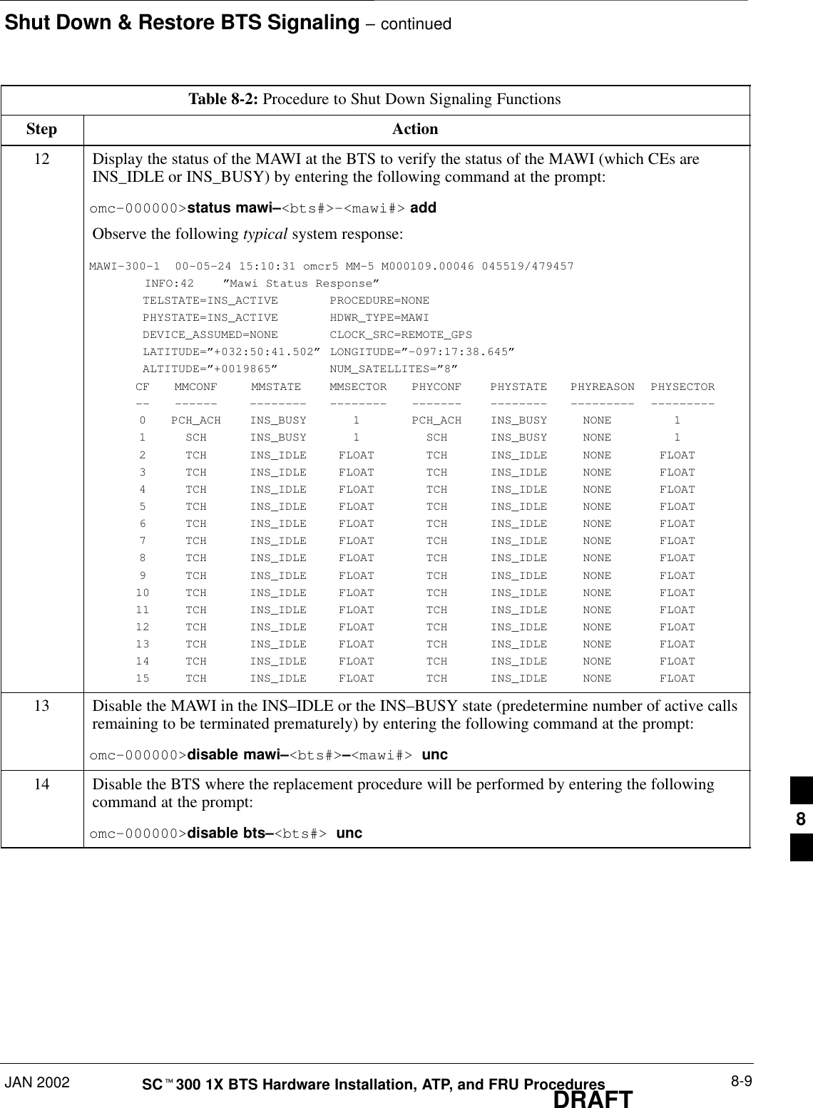
![Shut Down & Restore BTS Signaling – continuedDRAFTSCt300 1X BTS Hardware Installation, ATP, and FRU Procedures JAN 20028-8Table 8-2: Procedure to Shut Down Signaling FunctionsStep Action9View the existing congestion control parameters for all carriers equipped for the sector by enteringthe following command at the prompt:omc–000000>display sector–<bts#>–<sector#> congestconfObserve the following typical system display response:CARRIER NEWCALL REG AGG(bts#–sector#–carrier#) SET ALARMFLAG ALARMFLAG ALARMFLAG ANALOGREDIRECT GLOBALREDIRECT––––––––––––––––––––––– ––– ––––––––– –––––––––– –––––––––– –––––––––––––– ––––––––––––––300–1–4 1 ENABLE ENABLE ENABLE DISABLE DISABLE10 NOTEIn this step, you will change the value of the Global Service Redirection Flag(GLOBALREDIRECT) in the congestion control parameters so that the Global Service RedirectMessage is broadcast on the sector paging channel.Enter the following command at the prompt:omc–000000>edit sector–<bts#>–<sector#> congestconf !The system will prompt you to enter each control parameter value one at a time. Skip through theprompts until you get to the following:<globalredirect> , enter enable <globalredirect> , enter enable (This will force the Global Service Redirect Message to be broadcast on the sector pagingchannel.)The system will display the values of the control parameters. Verify that only theglobalredirect value changed.omc–000000>Accept [yes/no]?Enter Y to accept the change.Now the Global Service Redirection Message is sent over the sector paging channels. Allsubscribers are redirected away from the sector and onto a different system. This effectively shutsdown the sector.11 Display the status of the MAWI at the BTS by entering the following command at the prompt:omc–000000>display bts–<bts#> statusObserve the following typical system response for the entry of: DISPLAY BTS – 300 STATUSDEVSYNCConfig Calibration Calibration ISO RELATEDDEVICE CBSC STATUS Data Data Sync STATE–––––––––––––––––– –––– –––––– –––– –––– ––––––– ––––––––––––BTS–300 1 INS n/a n/a UNLOCKED UNLOCKEDBTSSPAN–300–1 1 INS n/a n/a n/a n/aBTSLINK–300–1 1 INS n/a n/a n/a n/aLPA–300–1 1 OOS_PARENT n/a n/a n/a n/aMDM–300–1 1 PRECUT n/a n/a n/a n/aMAWI–300–1 1 INS GOOD GOOD GOOD KEYED . . . continued on next page8](https://usermanual.wiki/Nokia-Solutions-and-Networks/T6CB1.Users-Manual-3-of-3/User-Guide-220230-Page-108.png)
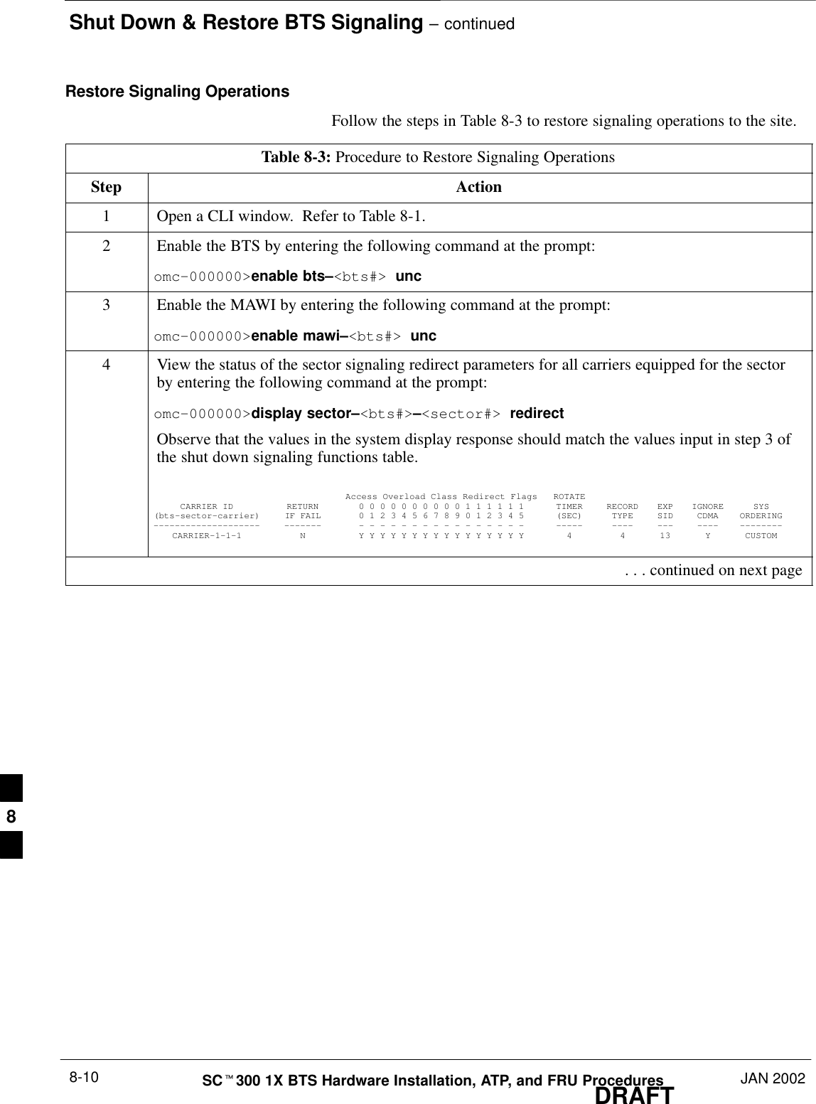
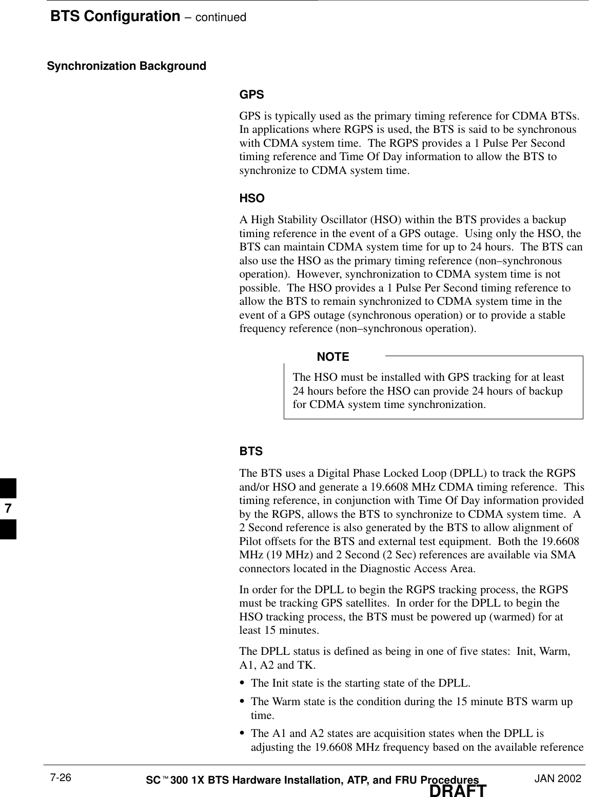
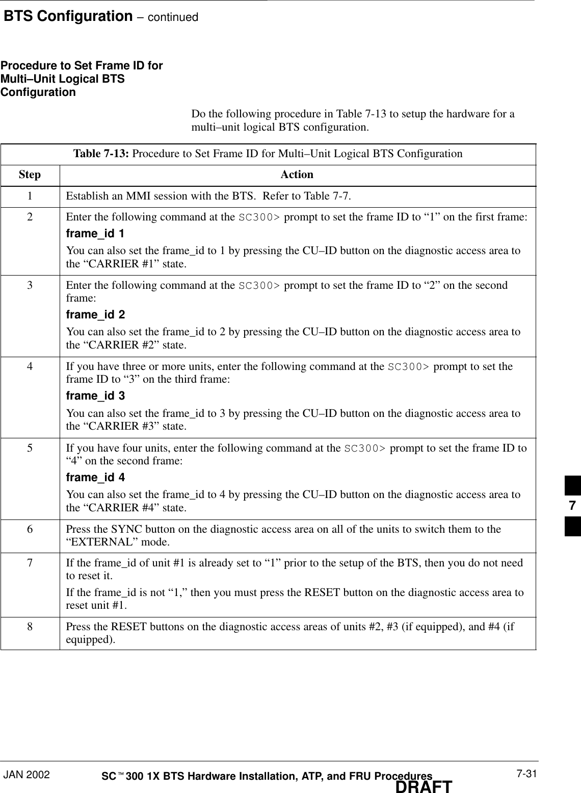
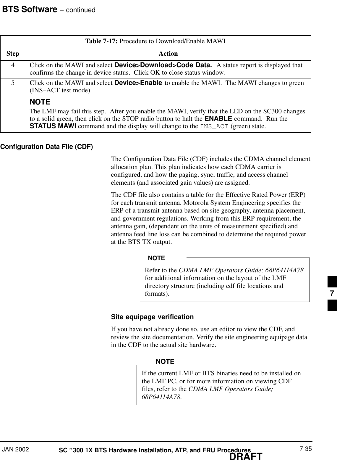
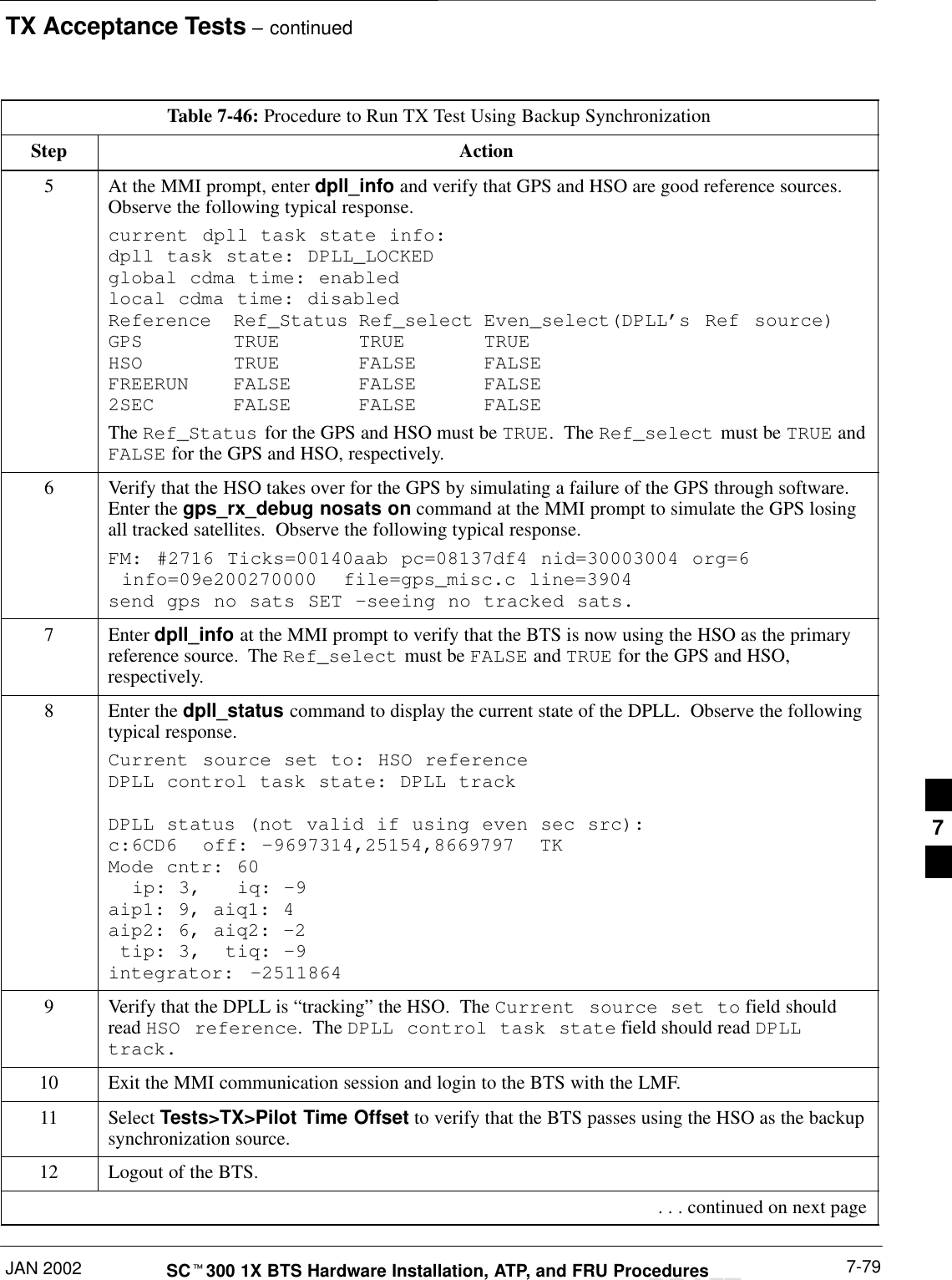
![Shut Down & Restore BTS Signaling – continuedJAN 2002 8-11SCt300 1X BTS Hardware Installation, ATP, and FRU ProceduresDRAFTTable 8-3: Procedure to Restore Signaling OperationsStep Action5* IMPORTANTIn this step, use the values recorded in step 2 of the shut down signaling functions table to answerthe prompts for the EDIT SECTOR REDIRECT command; except for record type enter 2.NOTEThis step shows the entry of initial standard values which is consistent with the original example;except record type must be 2. Your entries may be different.Restore the values of all redirect parameters by entering the following command at the prompt:omc–000000>edit sector–<bts#>–<sector#> redirect !The system will prompt you to enter each command parameter one at a time. Answer the promptsin the following order (Note that the following specified values are consistent with the originalexample. Yours may be different):<accolc0> Enter N, <accolc1> Enter N, ... <accolc15> enter N<returniffail> , enter N<recordtype> , enter 2<expe tedsid><expectedsid> , enter 0<ignorecdma> , enter N<sysordering> , enter custom<rotatetimer> , enter 4The system will display the command that will be sent. Verify the command syntax.omc–000000>Accept [yes/no]?Enter Y to accept the command.6View the status of the sector signaling redirect parameters to verify that the sector is ready formaintenance.omc–000000>display sector–<bts#>–<sector#> redirectEnsure that the values in the system display response match the values input by the operator instep 5 (see example below).Access Overload Class Redirect Flags ROTATECARRIER ID RETURN 0 0 0 0 0 0 0 0 0 0 1 1 1 1 1 1 TIMER RECORD EXP IGNORE SYS(bts–sector–carrier) IF FAIL 0 1 2 3 4 5 6 7 8 9 0 1 2 3 4 5 (SEC) TYPE SID CDMA ORDERING–––––––––––––––––––– ––––––– – – – – – – – – – – – – – – – – ––––– –––– ––– –––– ––––––––CARRIER–1–1–1 N N N N N N N N N N N N N N N N N 4 2 0 N CUSTOM . . . continued on next page8](https://usermanual.wiki/Nokia-Solutions-and-Networks/T6CB1.Users-Manual-3-of-3/User-Guide-220230-Page-111.png)
![Shut Down & Restore BTS Signaling – continuedDRAFTSCt300 1X BTS Hardware Installation, ATP, and FRU Procedures JAN 20028-12Table 8-3: Procedure to Restore Signaling OperationsStep Action7View the congestion control parameters for all carriers equipped for the sector by entering thefollowing command at the prompt:omc–000000>display sector–<bts#>–<sector#> congestconfObserve the following typical system display response:CARRIER NEWCALL REG AGG(bts#–sector#–carrier#) SET ALARMFLAG ALARMFLAG ALARMFLAG ANALOGREDIRECT GLOBALREDIRECT––––––––––––––––––––––– ––– ––––––––– ––––––––– ––––––––– –––––––––––––– ––––––––––––––300–1–4 1 ENABLE ENABLE ENABLE DISABLE ENABLE8NOTEIn this step, you will change the value of the Global Service Redirection Flag(GLOBALREDIRECT) in the congestion control parameters so that the Global Service RedirectMessage is only broadcast on the sector paging channel when there is traffic congestion in thesector.Enter the following command at the prompt:omc–000000>edit sector–<bts#>–<sector#> congestconf !The system will prompt you to enter each control parameter value one at a time. Skip through theprompts until you get to the following:<globalredirect> , enter disable (This will revert the Global Service Redirect Message to congestion control.)The system will display the values of the control parameters. Verify that only theGLOBALREDIRECT value changed.omc–000000>Accept [yes/no]?Enter Y to accept the change.Now the Global Service Redirection Message will only be sent over the sector paging channelswhen there is traffic congestion in the sector.9Display the status of the MAWI at the BTS by entering the following command at the prompt:omc–000000>display bts–<bts#> statusObserve the following typical system response:DEVSYNCConfig Calibration Calibration ISO RELATEDDEVICE CBSC STATUS Data Data Sync STATE–––––––––––––––––– –––– –––––– –––– –––– ––––––– ––––––––––––BTS–300 1 INS n/a n/a UNLOCKED UNLOCKEDBTSSPAN–300–1 1 INS n/a n/a n/a n/aBTSLINK–300–1 1 INS n/a n/a n/a n/aLPA–300–1 1 OOS_PARENT n/a n/a n/a n/aMDM–300–1 1 PRECUT n/a n/a n/a n/aMAWI–300–1 1 INS GOOD GOOD GOOD KEYED . . . continued on next page8](https://usermanual.wiki/Nokia-Solutions-and-Networks/T6CB1.Users-Manual-3-of-3/User-Guide-220230-Page-112.png)