Nokia Solutions and Networks T5GX1 UBS CDMA XMI Transceiver at 800 MHz User Manual Exhibit 123b
Nokia Solutions and Networks UBS CDMA XMI Transceiver at 800 MHz Exhibit 123b
UserManual.wiki
>
Nokia Solutions and Networks
>
T5GX1 User Manual
>
Exhibit 123b
Contents
1.
Exhibit 12
2.
Exhibit 121a
3.
Exhibit 121b
4.
Exhibit 122a
5.
Exhibit 122b
6.
Exhibit 122c
7.
Exhibit 123a
8.
Exhibit 123b
9.
Exhibit 123c
10.
Exhibit 123d
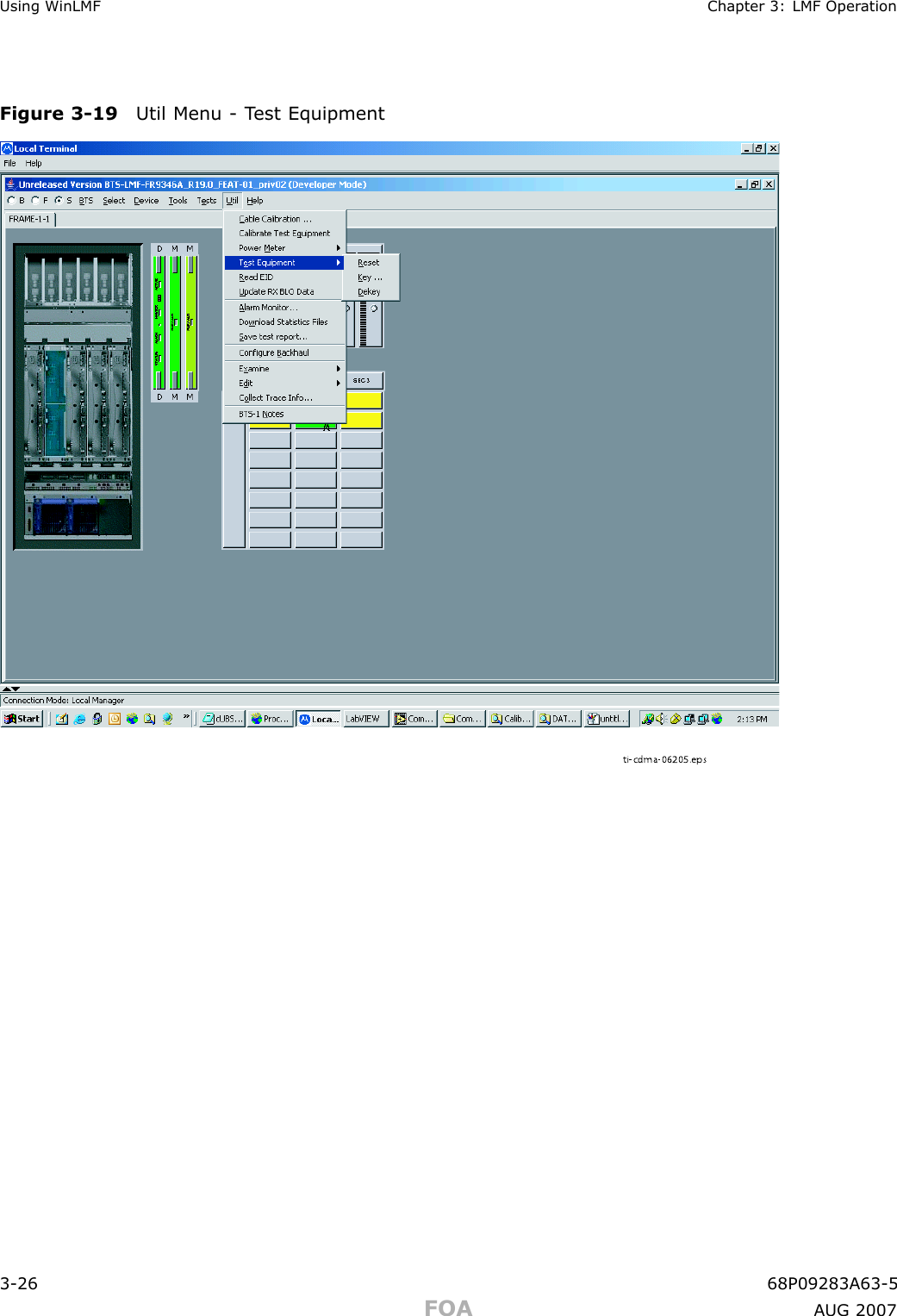
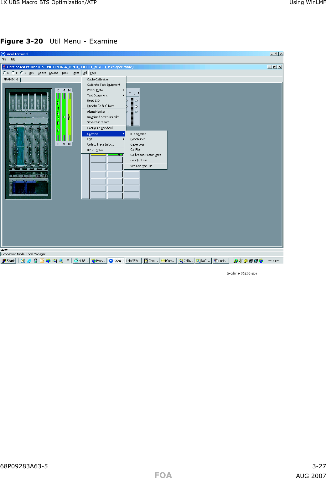
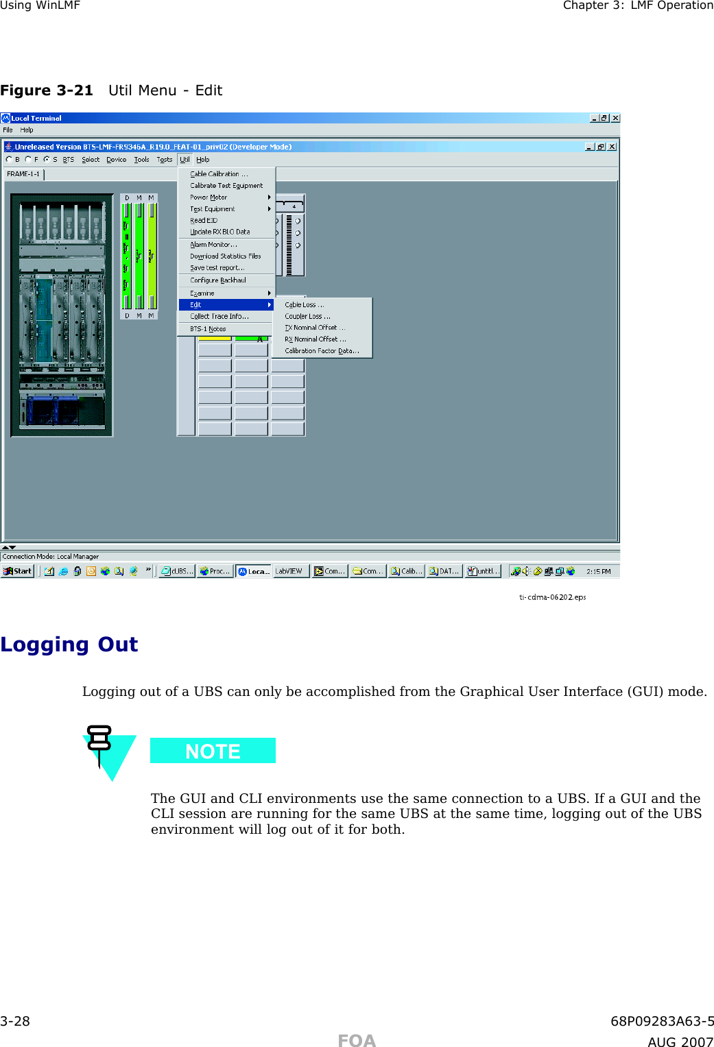
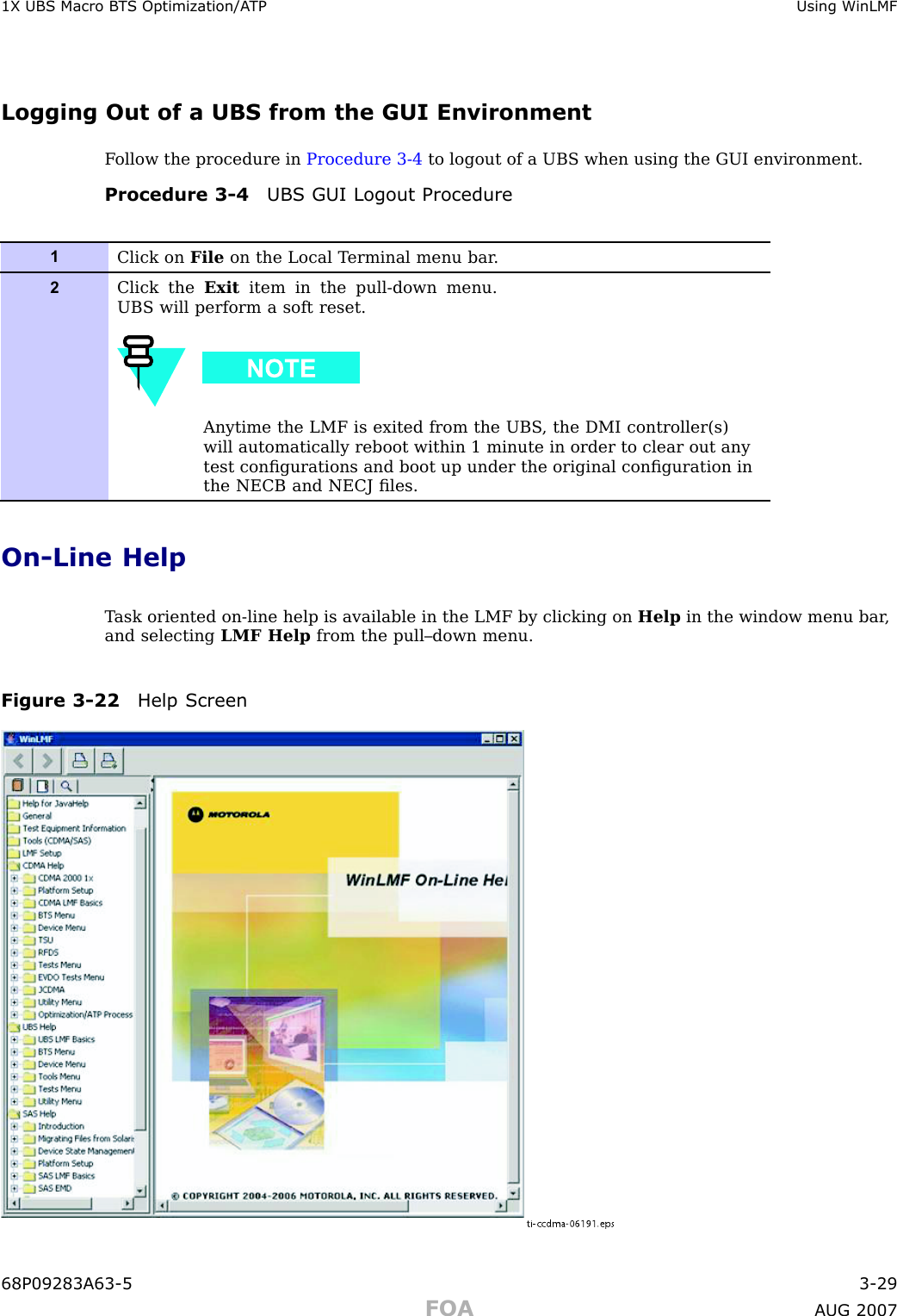
Exhibit 123b
Navigation menu
Upload a User Manual
Namespaces
Wiki Guide
HTML
PDF
Info
Views
User Manual
Discussion / Help
Navigation
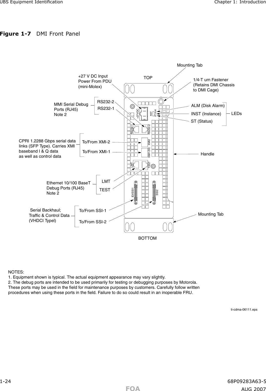
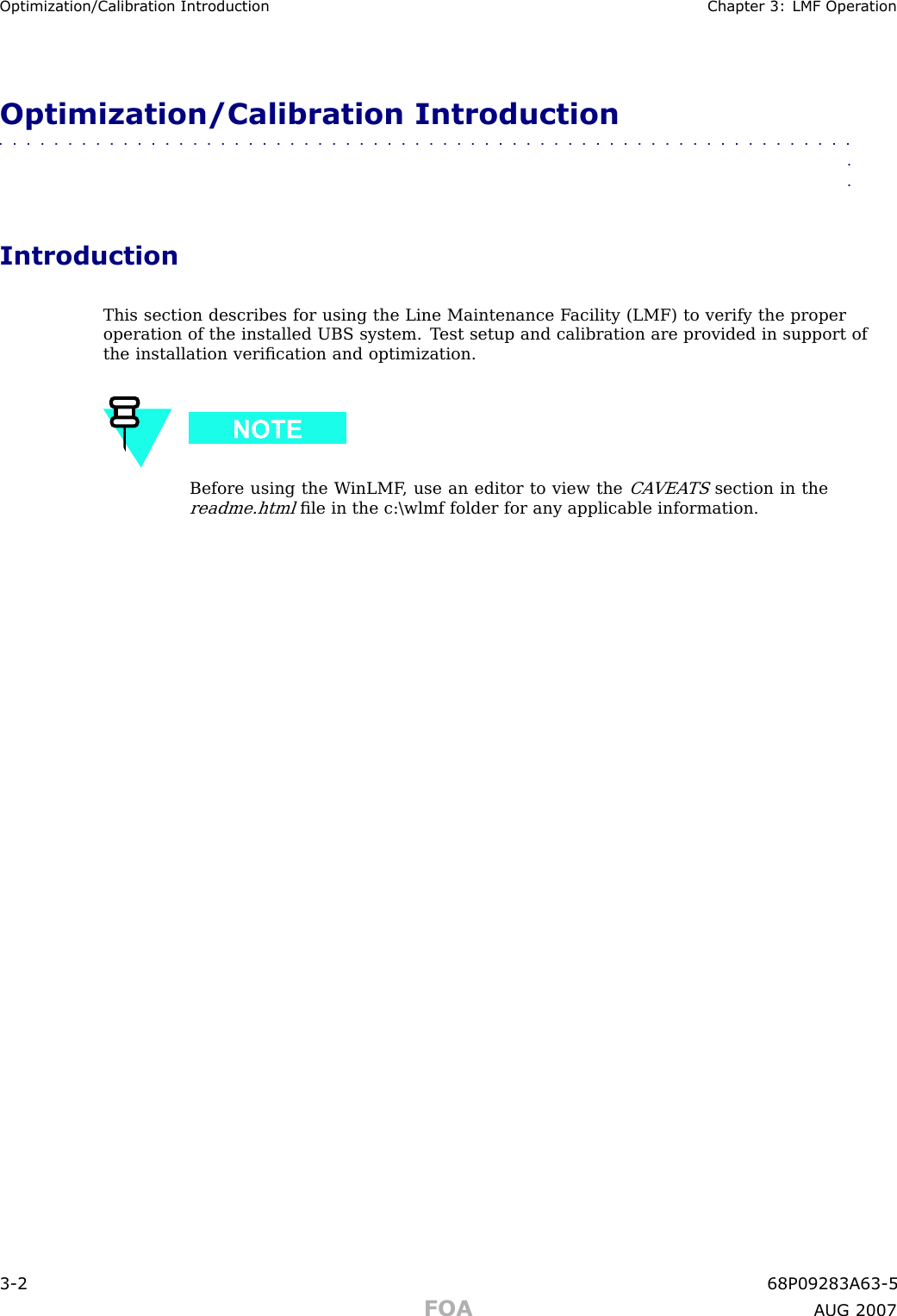
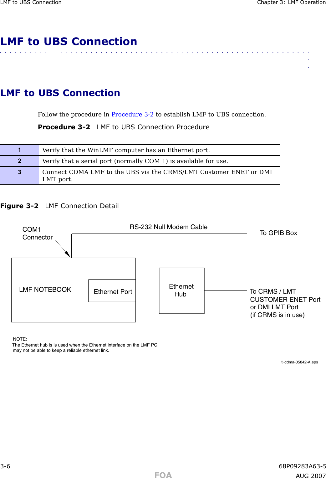
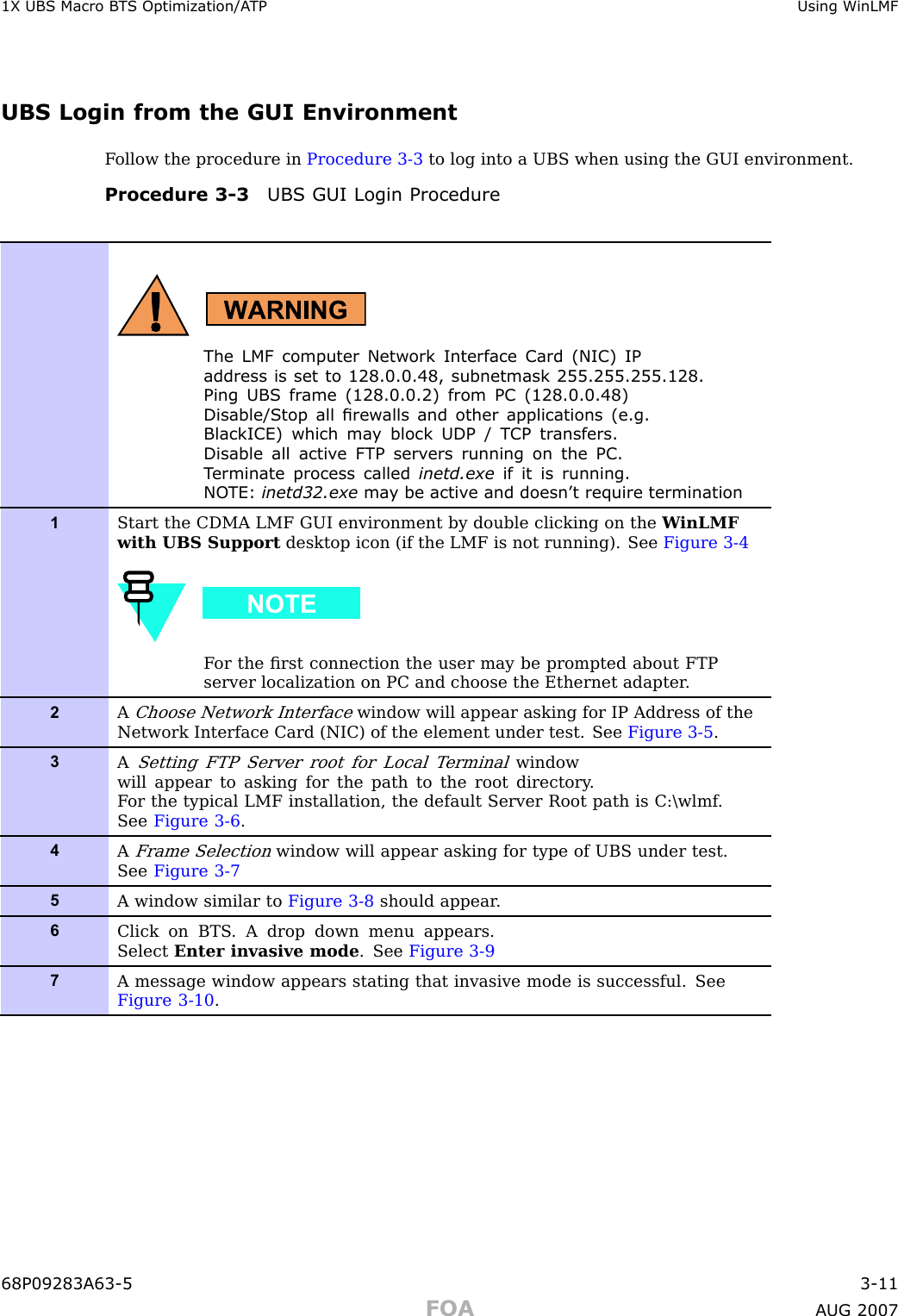
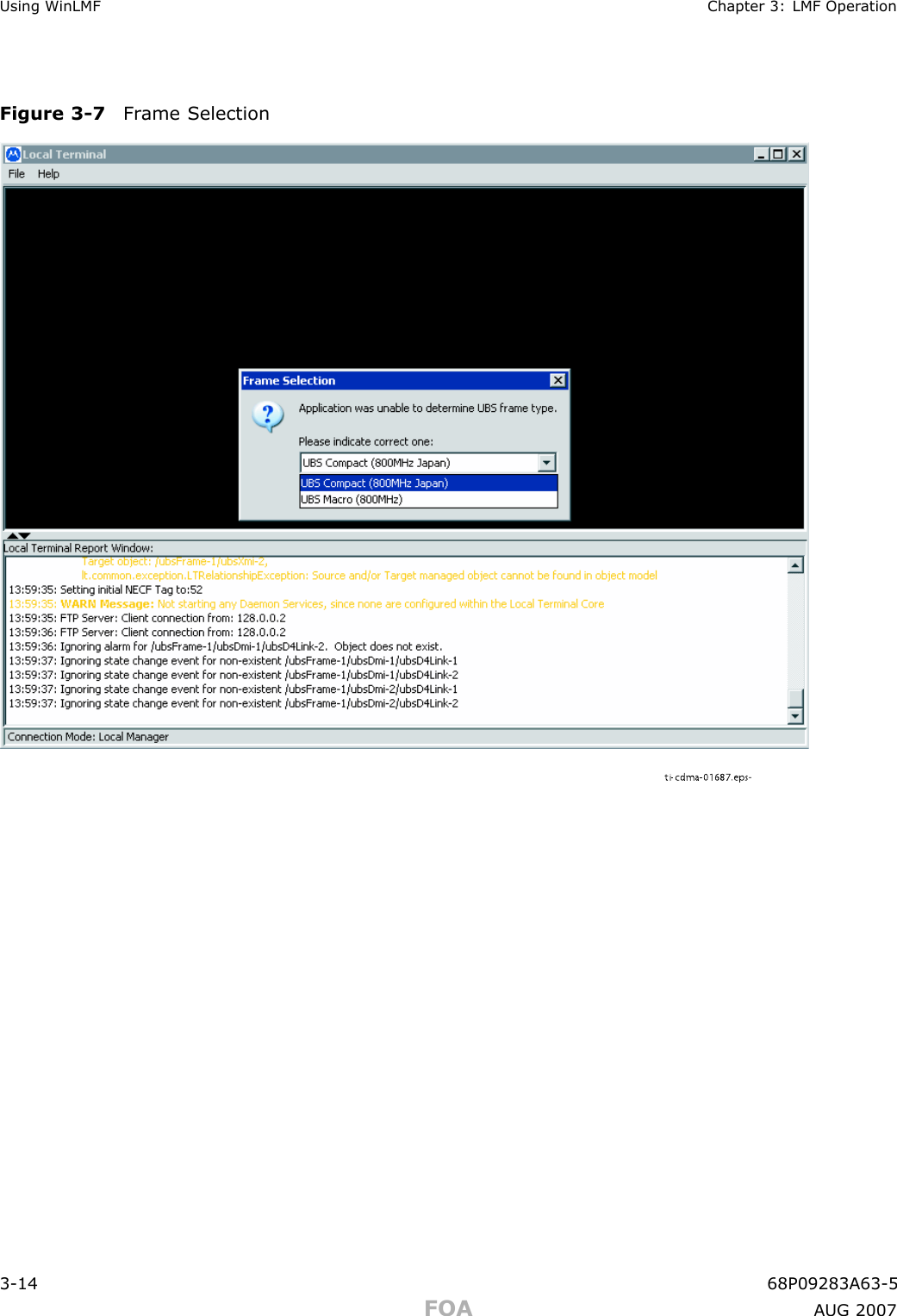
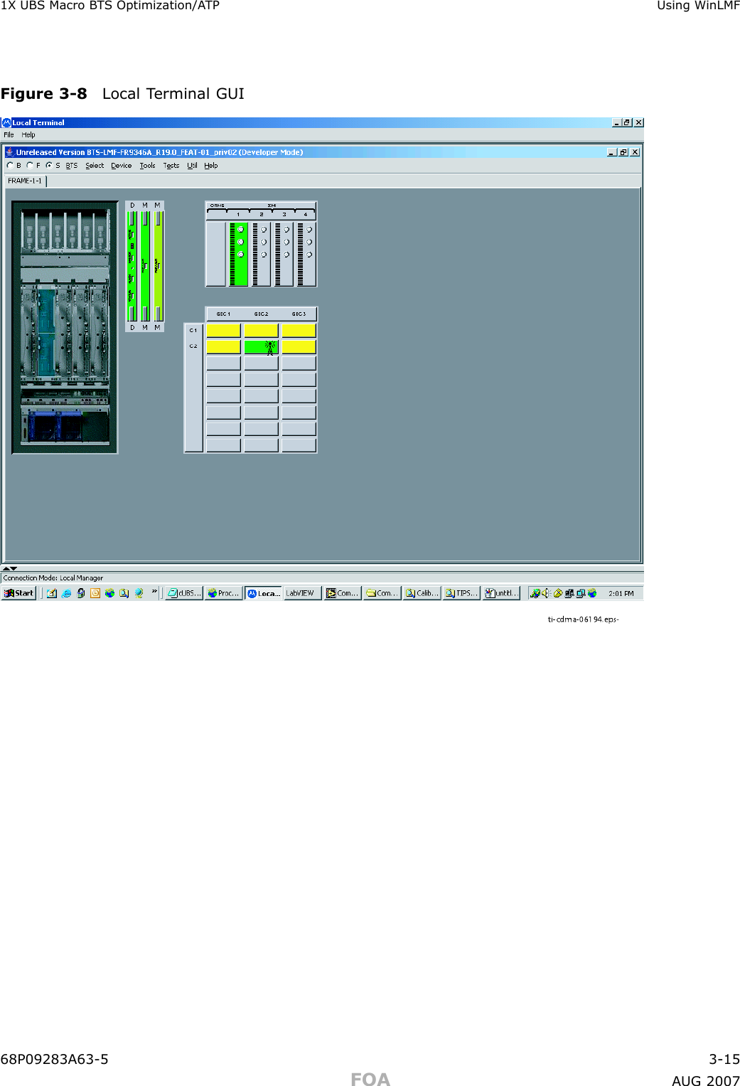
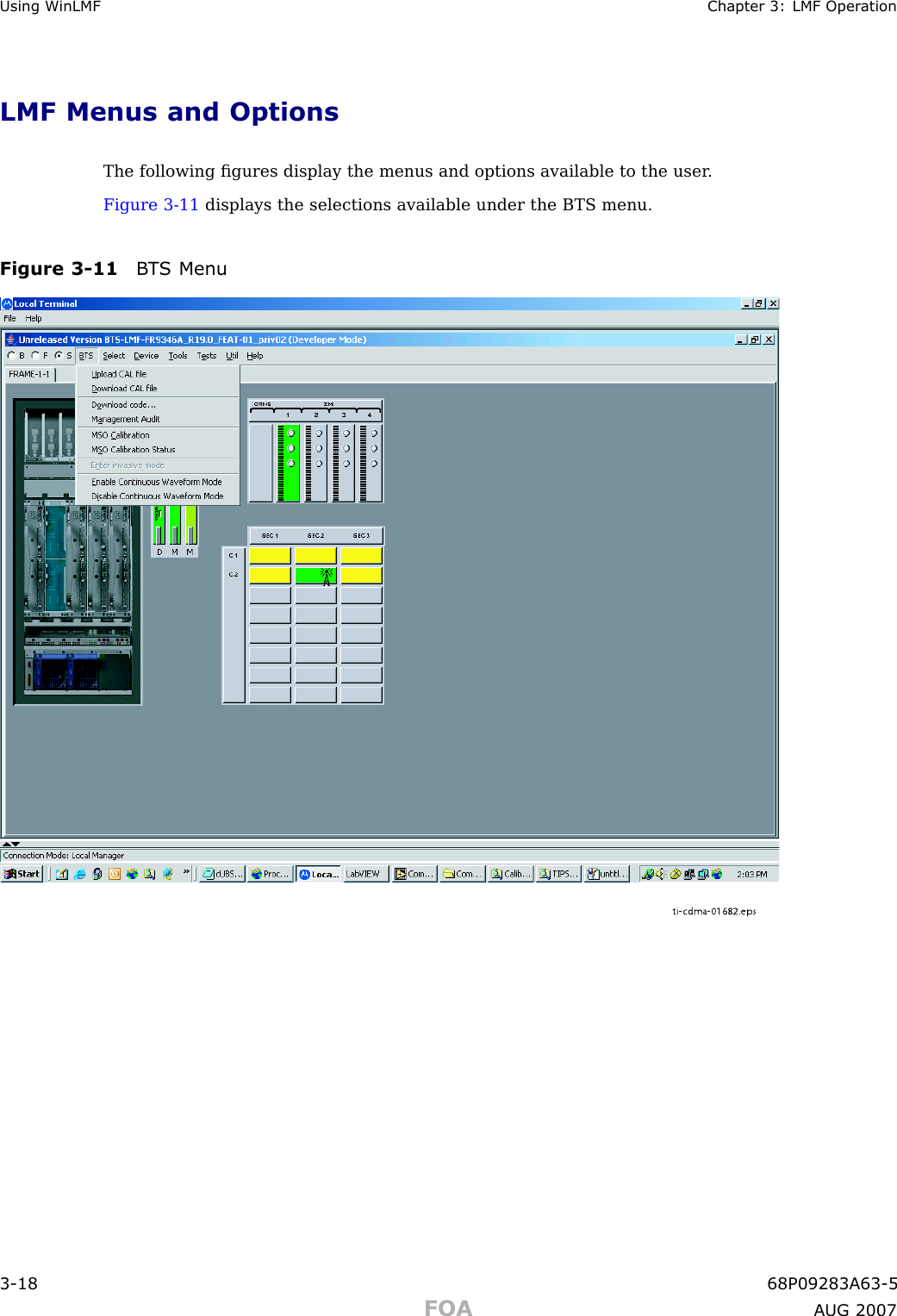
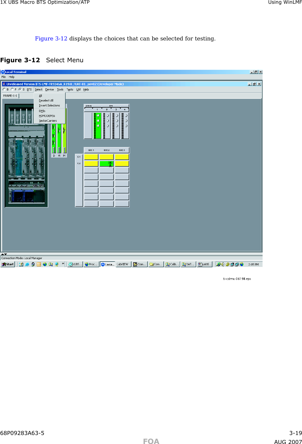
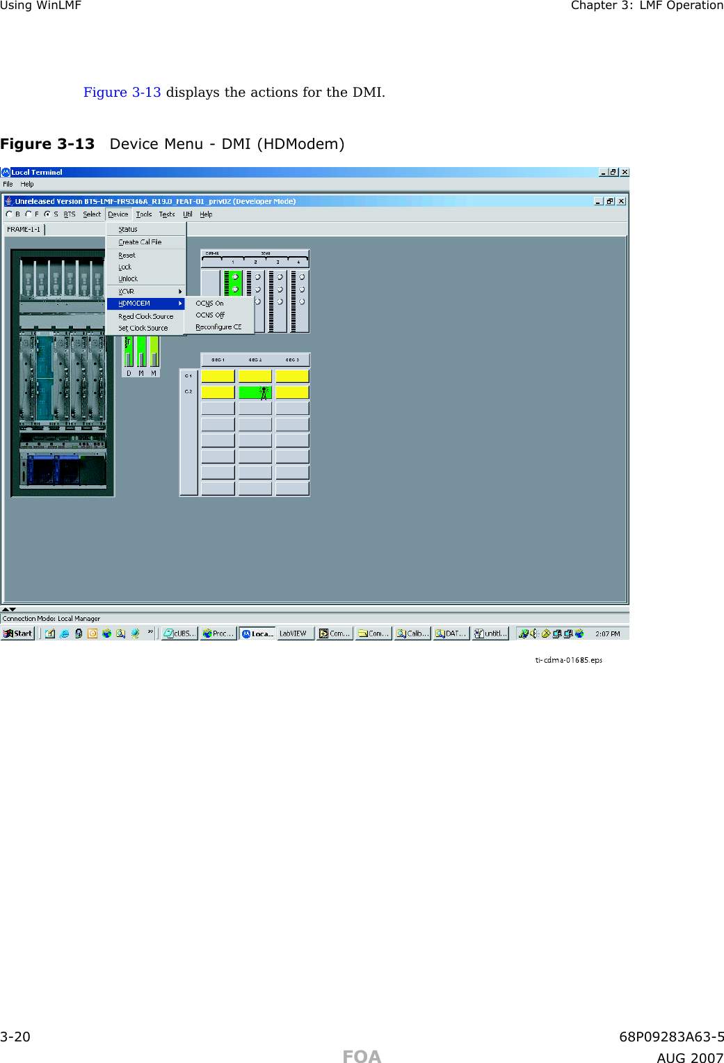
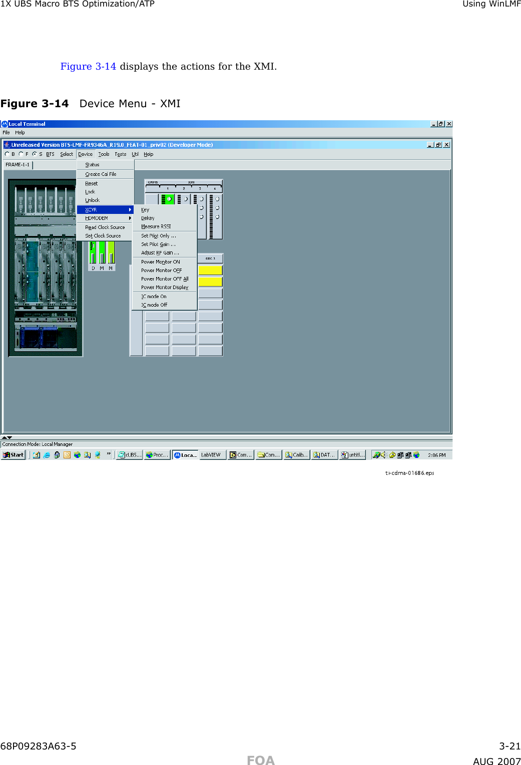
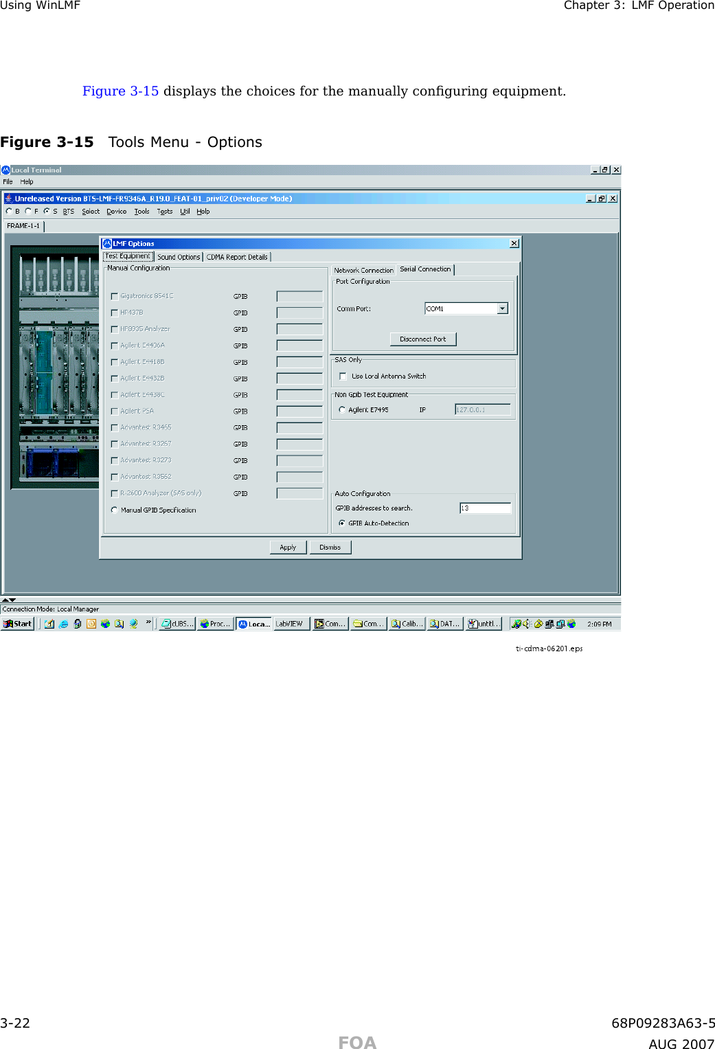
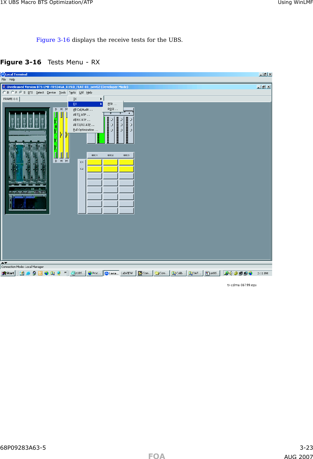
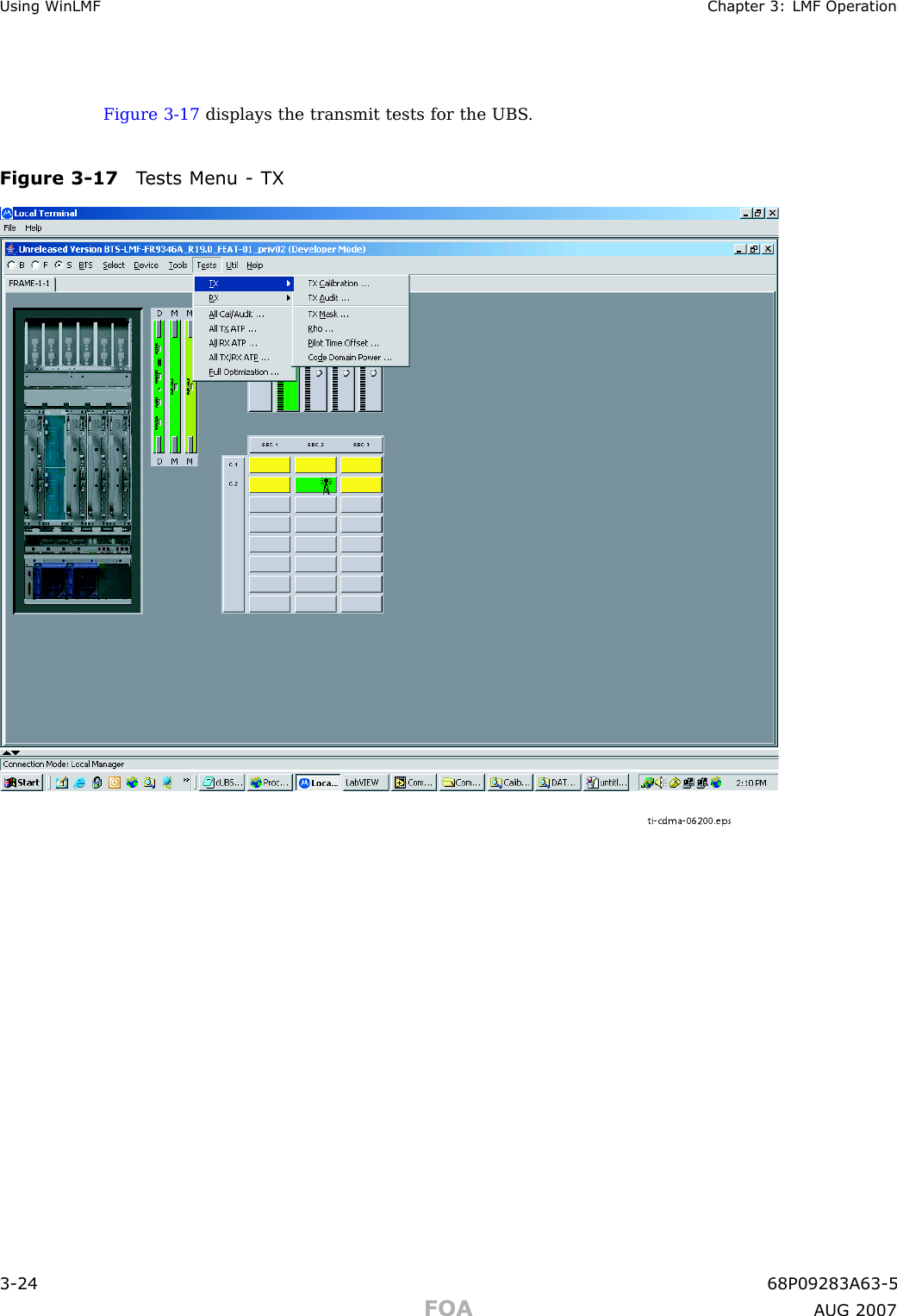
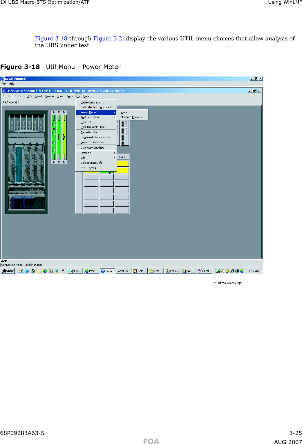
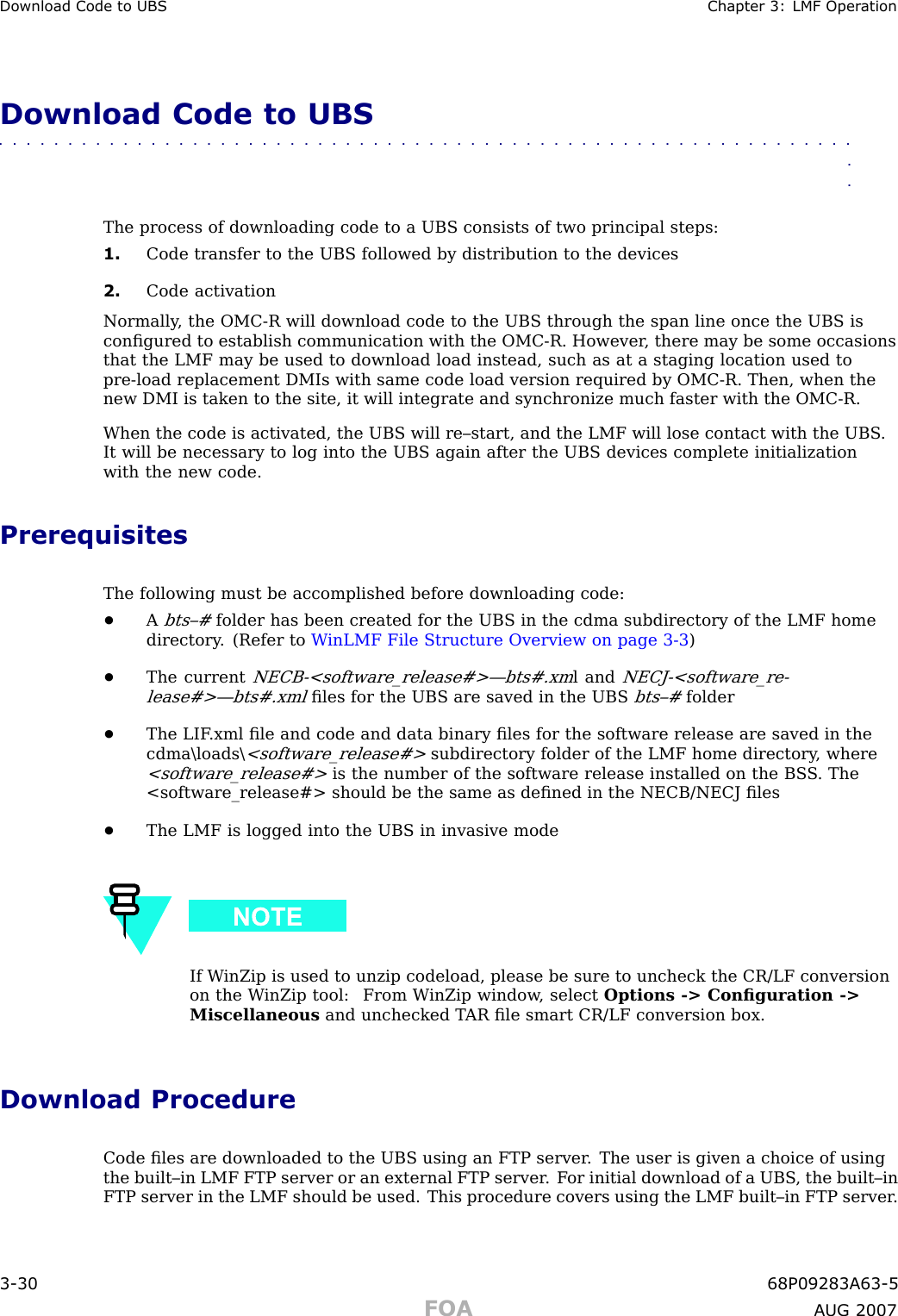
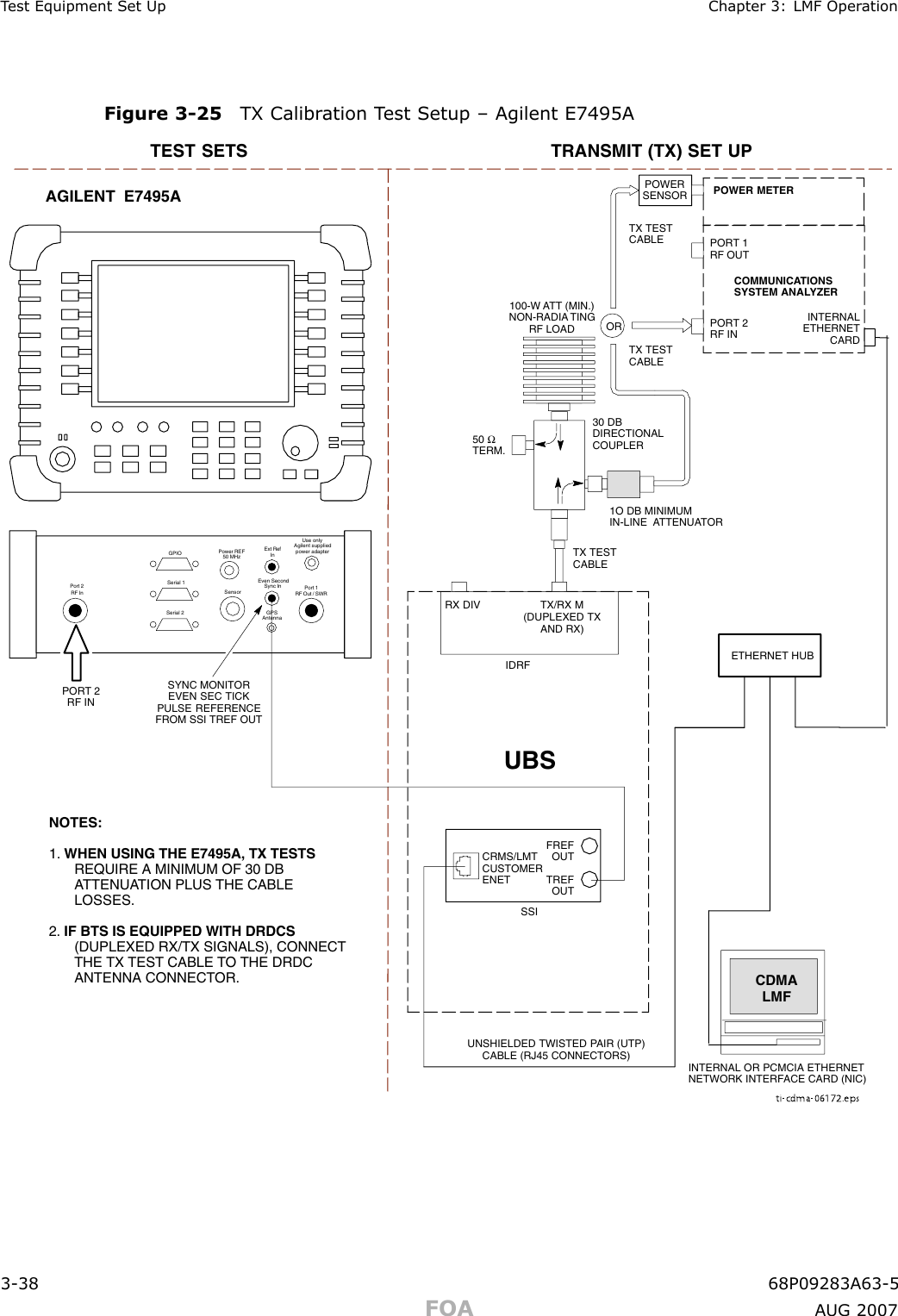
![1X UBS Macro B T S Optimization/A TP Using WinLMFCLI Format ConventionsThe CLI command can be broken down in the following way:•verb•device including device identifier parameters•switch•option parameterskeywordsequal signsparameter valuesSpaces are required between the verb, device, switch, and option parameters. A hyphen is re-quired between the device and its identifiers. The following is an example of a UBS CLI command:configure sc -<bts#> -<sector#> -<carrier#> pgain=<pgain#>mdm_slot=<mdm_slot#> ce=<ce#> [pnoffset=<pnoffset#>]Refer to theW inLMF CDMA CLI Commands – 68P09275A12manual for further informationon CLI commands and their use.Logging into a UBSLogging into a UBS establishes a communications link between the UBS and the LMF . An LMFsession can be logged into only one UBS at a time.PrerequisitesBefore attempting to login to a UBS , ensure the following have been completed:•The LMF is properly connected to the UBS (see Figure 3 -2 )•The LMF application program is correctly installed and prepared•Preparing the LMF for Connectivity and Configuring the Controller of UBS proceduresare completed•The LMF computer was connected to the UBS before starting the W indows operatingsystem and LMF software. If necessary , restart the computer after connecting it to theUBS in accordance with Procedure 3 -3 and Figure 3 -2 .•When the PC has completed startup, click on WinLMF with UBS Support icon Figure 3 -3to bring up the Local T erminal window ( Figure 3 -4 )•IP Address is 128.0.0.xxx•Netmask address is 255.255.255.128•BlackICE or other similar process is disabled•W indowInternet Connection Firewalland other firewall programs should be disabled•Java Runtime Environment (JRE) is installed and version matched68P09283A63 -5 3 -9FOA A UG 2007](https://usermanual.wiki/Nokia-Solutions-and-Networks/T5GX1.Exhibit-123b/User-Guide-854643-Page-19.png)