Nokia Solutions and Networks T5GX1 UBS CDMA XMI Transceiver at 800 MHz User Manual Exhibit 121b
Nokia Solutions and Networks UBS CDMA XMI Transceiver at 800 MHz Exhibit 121b
UserManual.wiki
>
Nokia Solutions and Networks
>
T5GX1 User Manual
>
Exhibit 121b
Contents
1.
Exhibit 12
2.
Exhibit 121a
3.
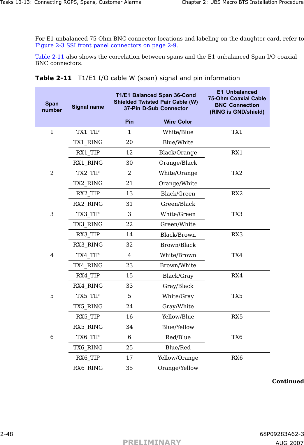
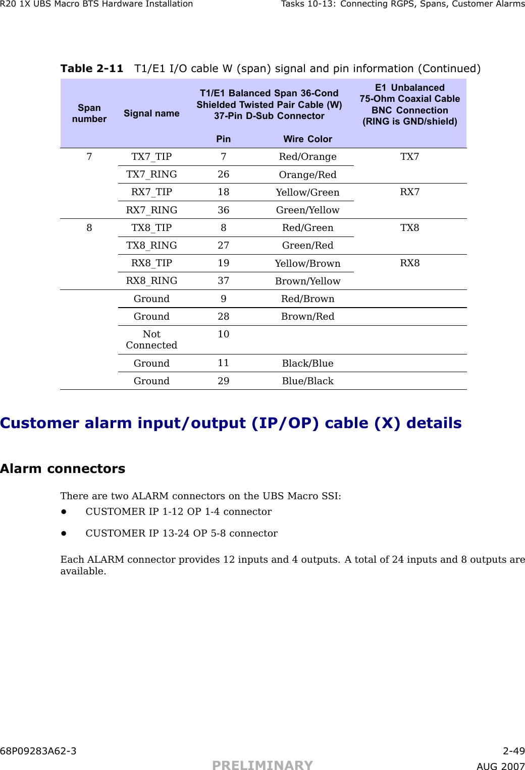
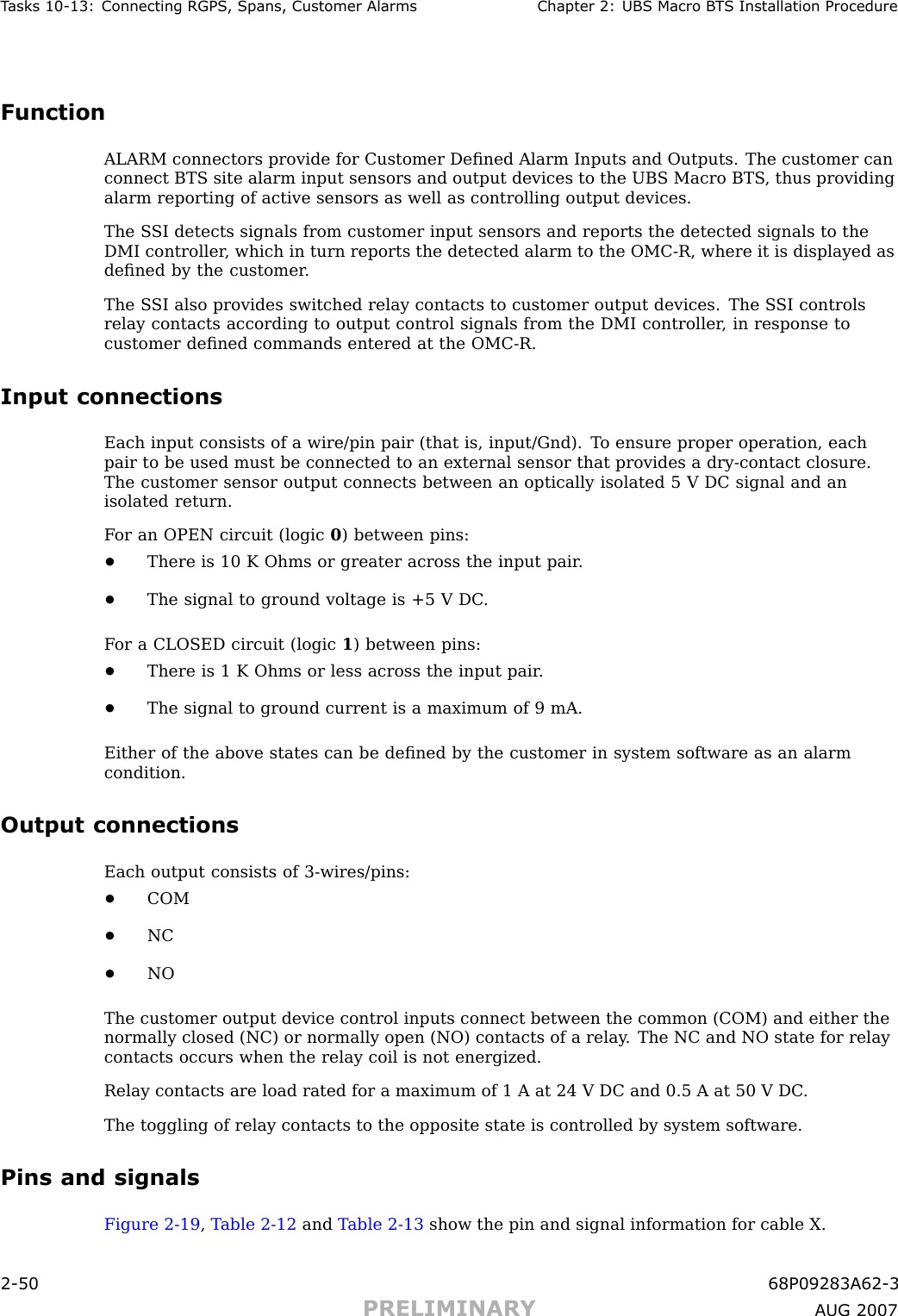
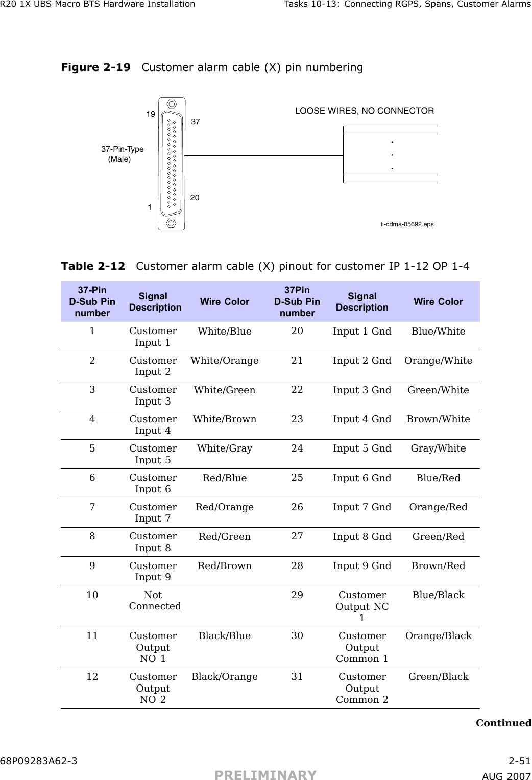
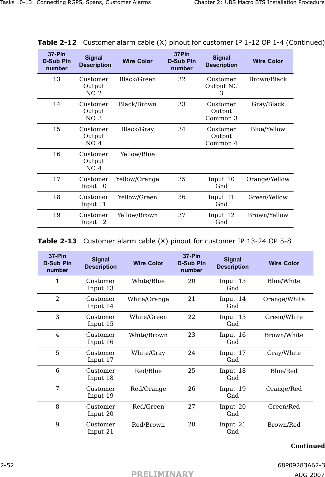
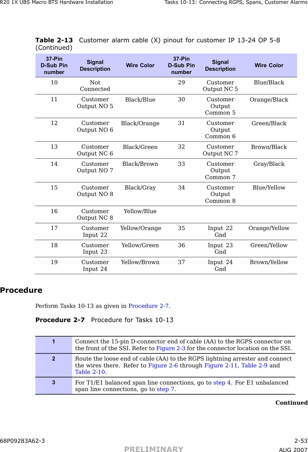
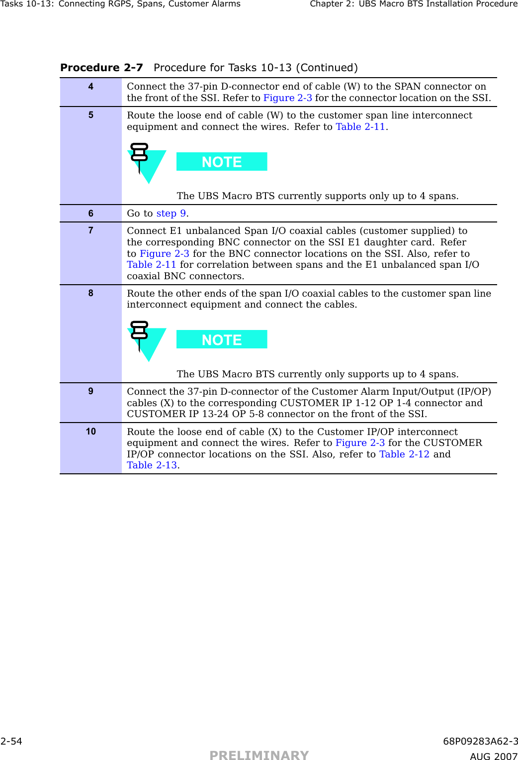
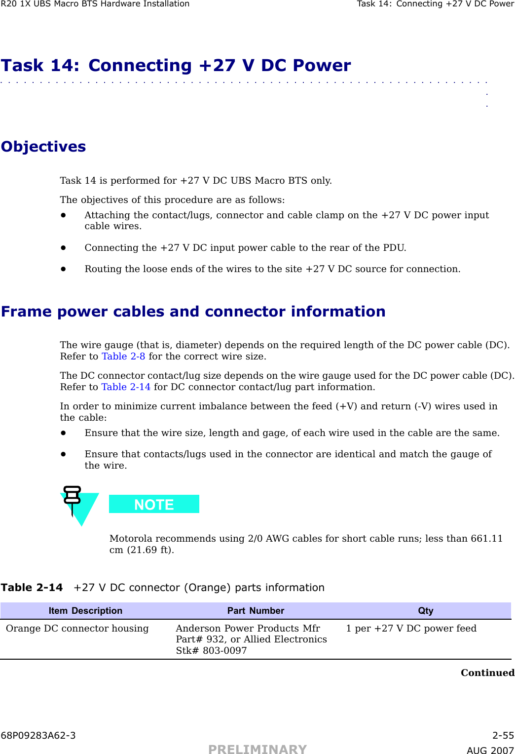
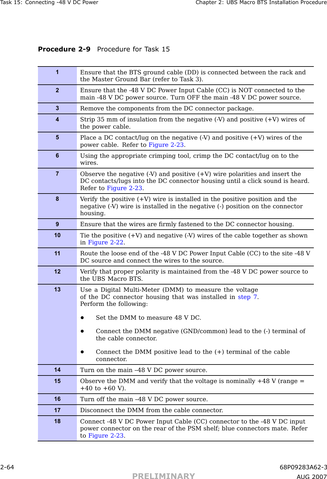
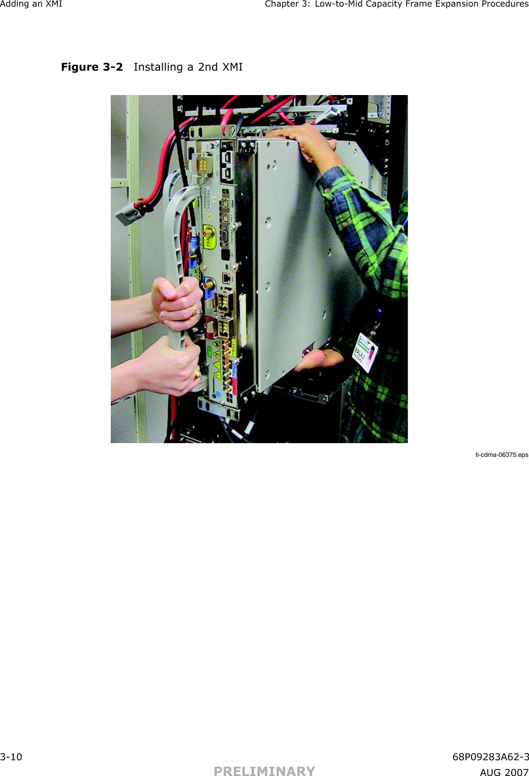
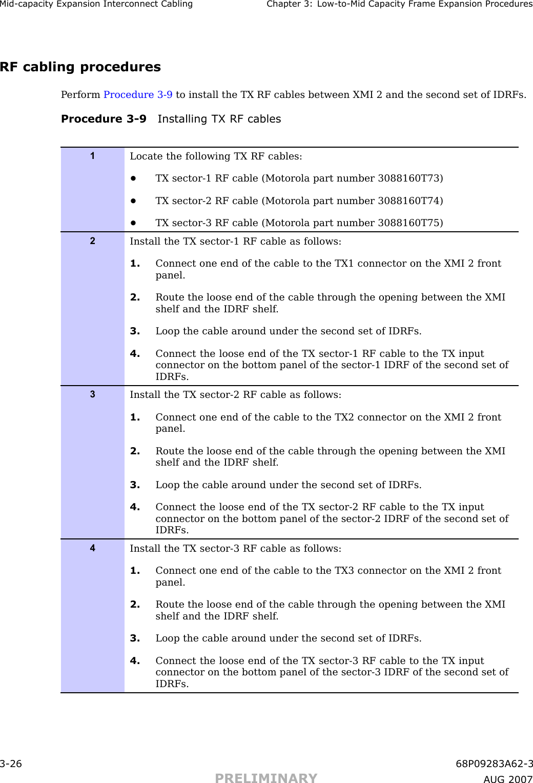
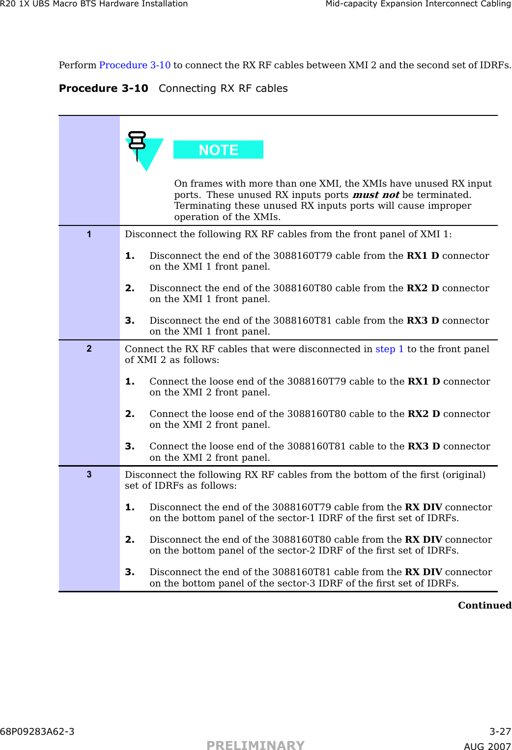
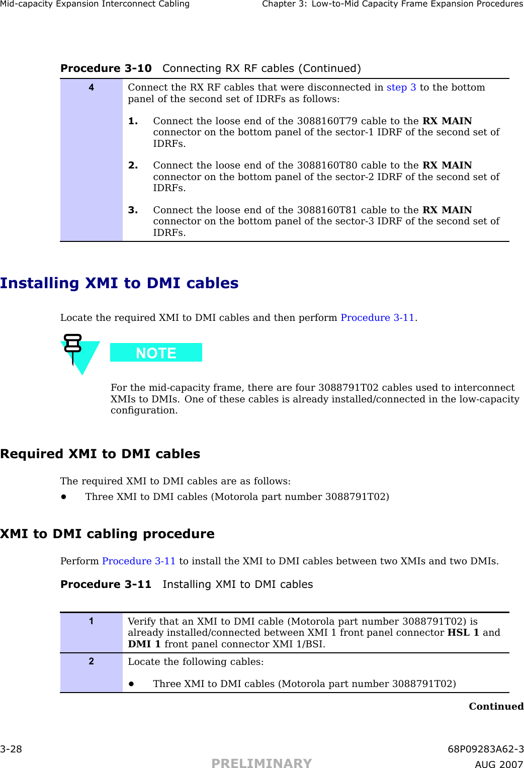
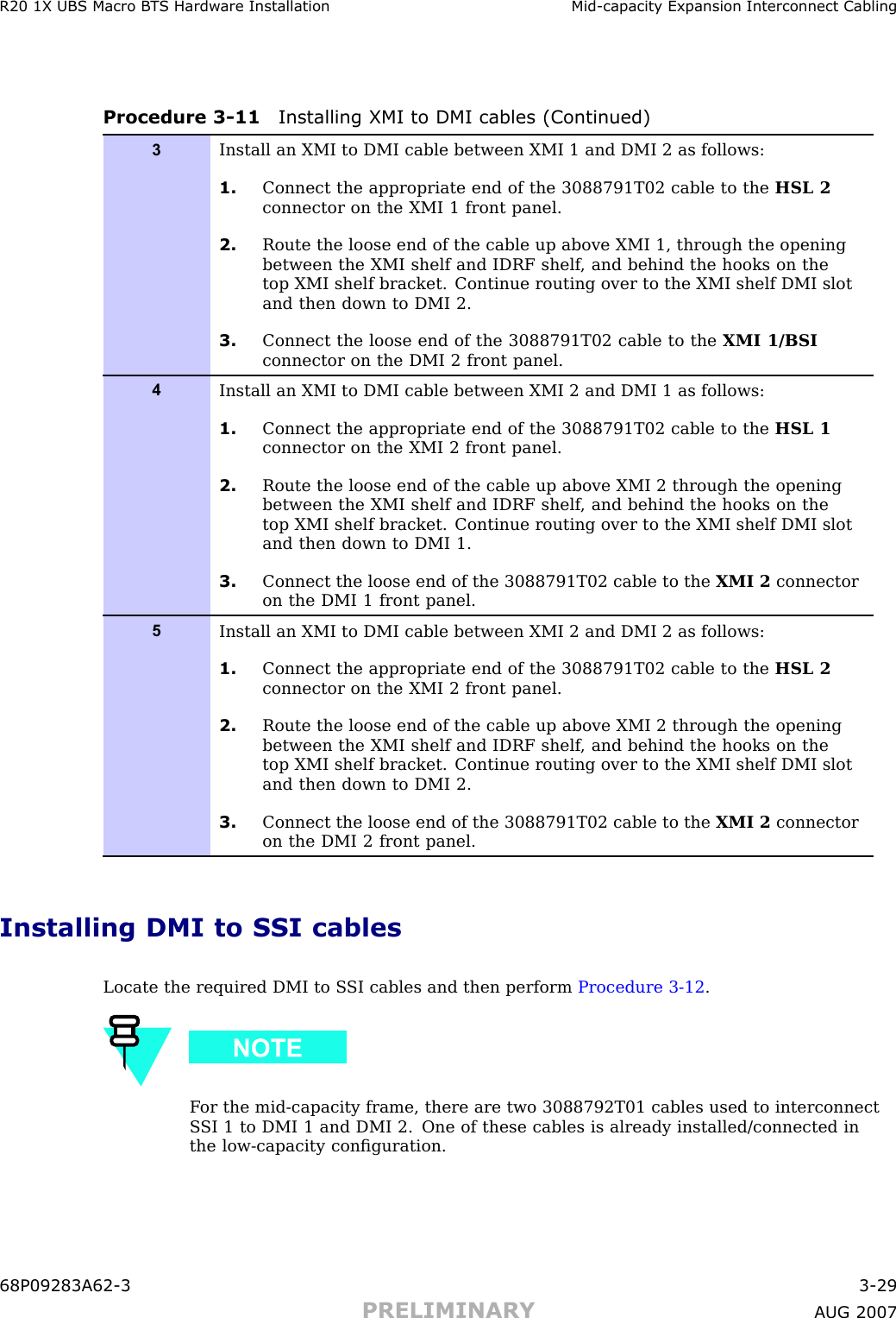
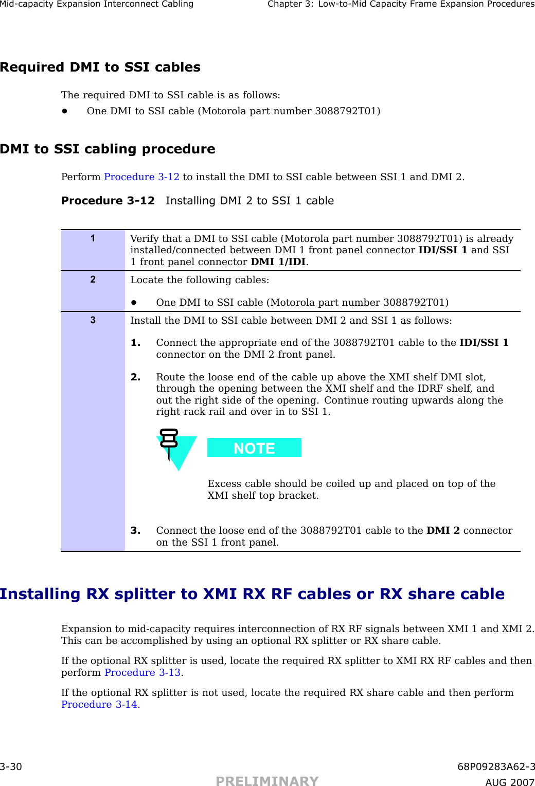
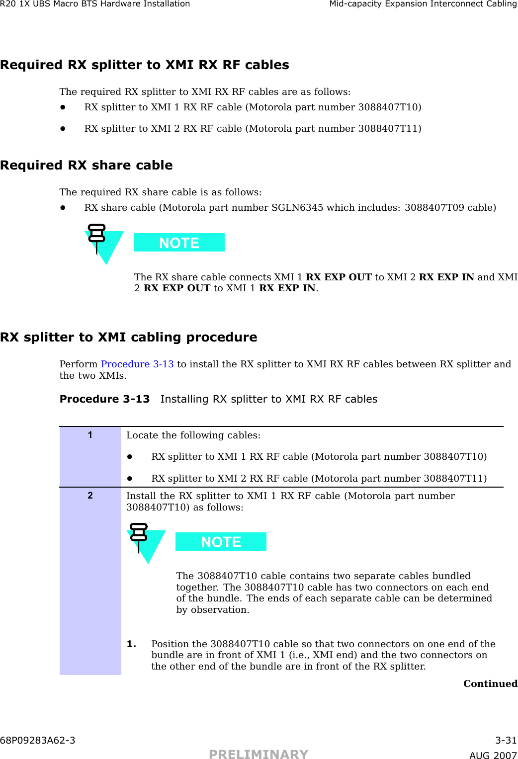
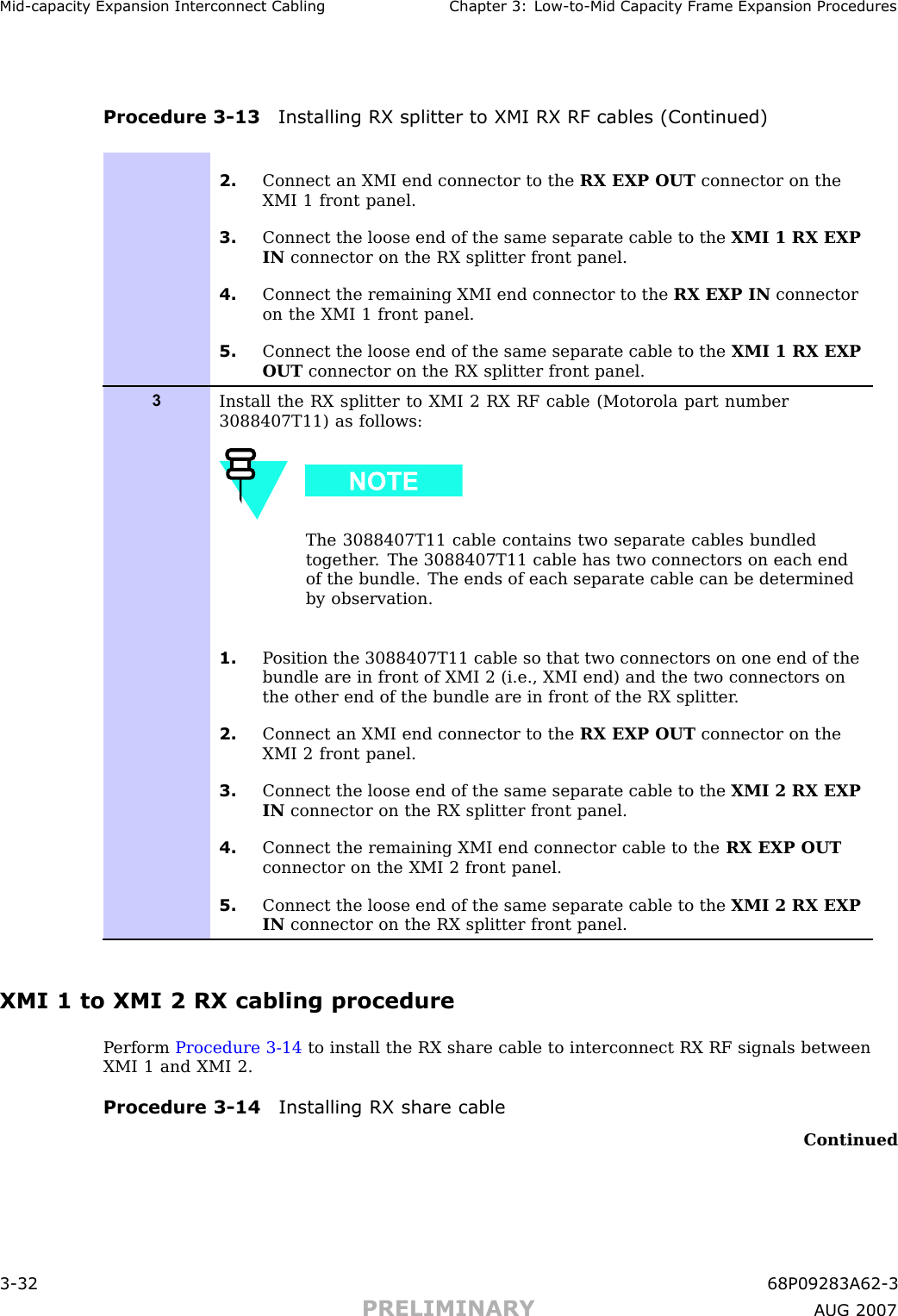
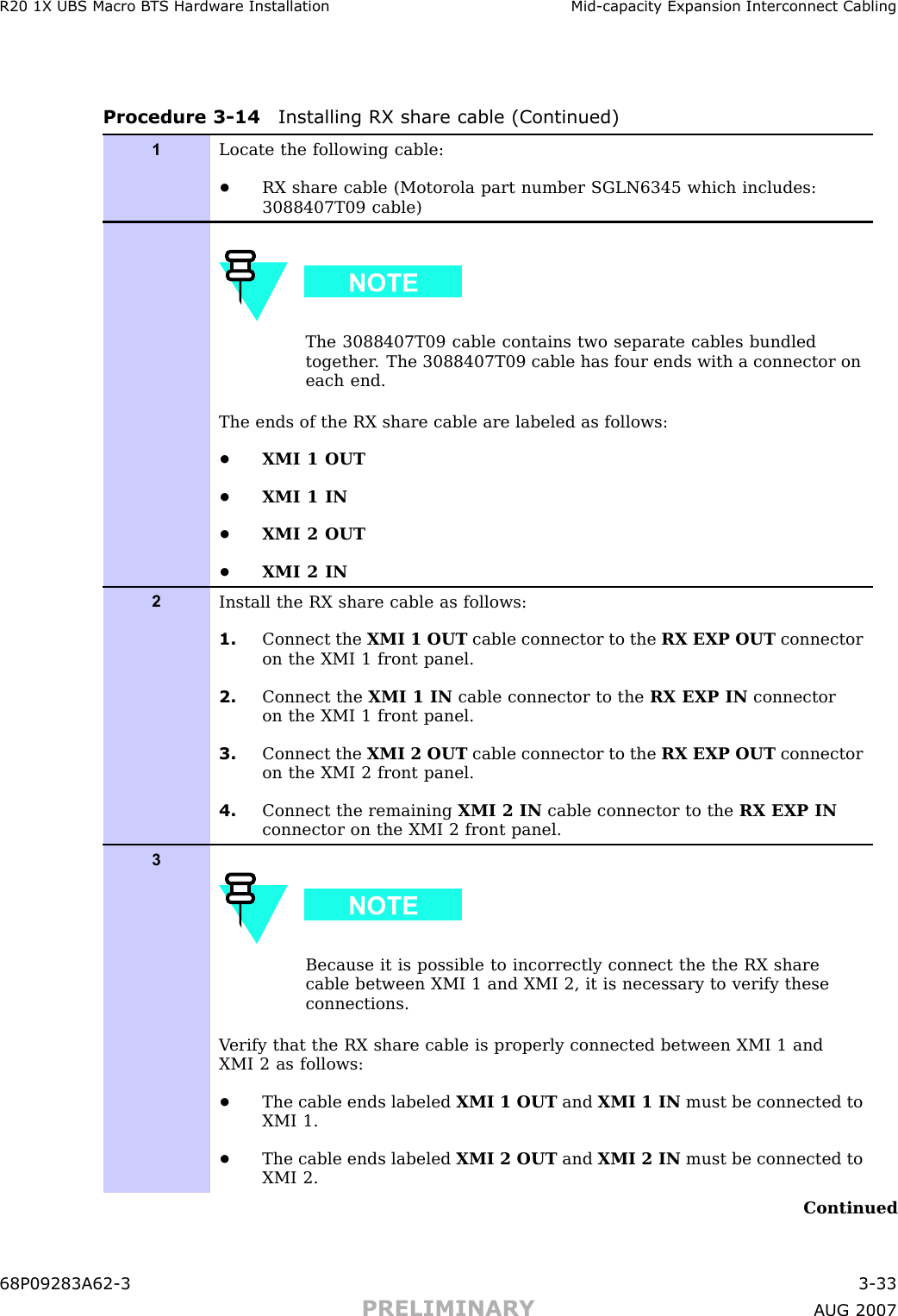
Exhibit 121b
4.
Exhibit 122a
5.
Exhibit 122b
6.
Exhibit 122c
7.
Exhibit 123a
8.
Exhibit 123b
9.
Exhibit 123c
10.
Exhibit 123d
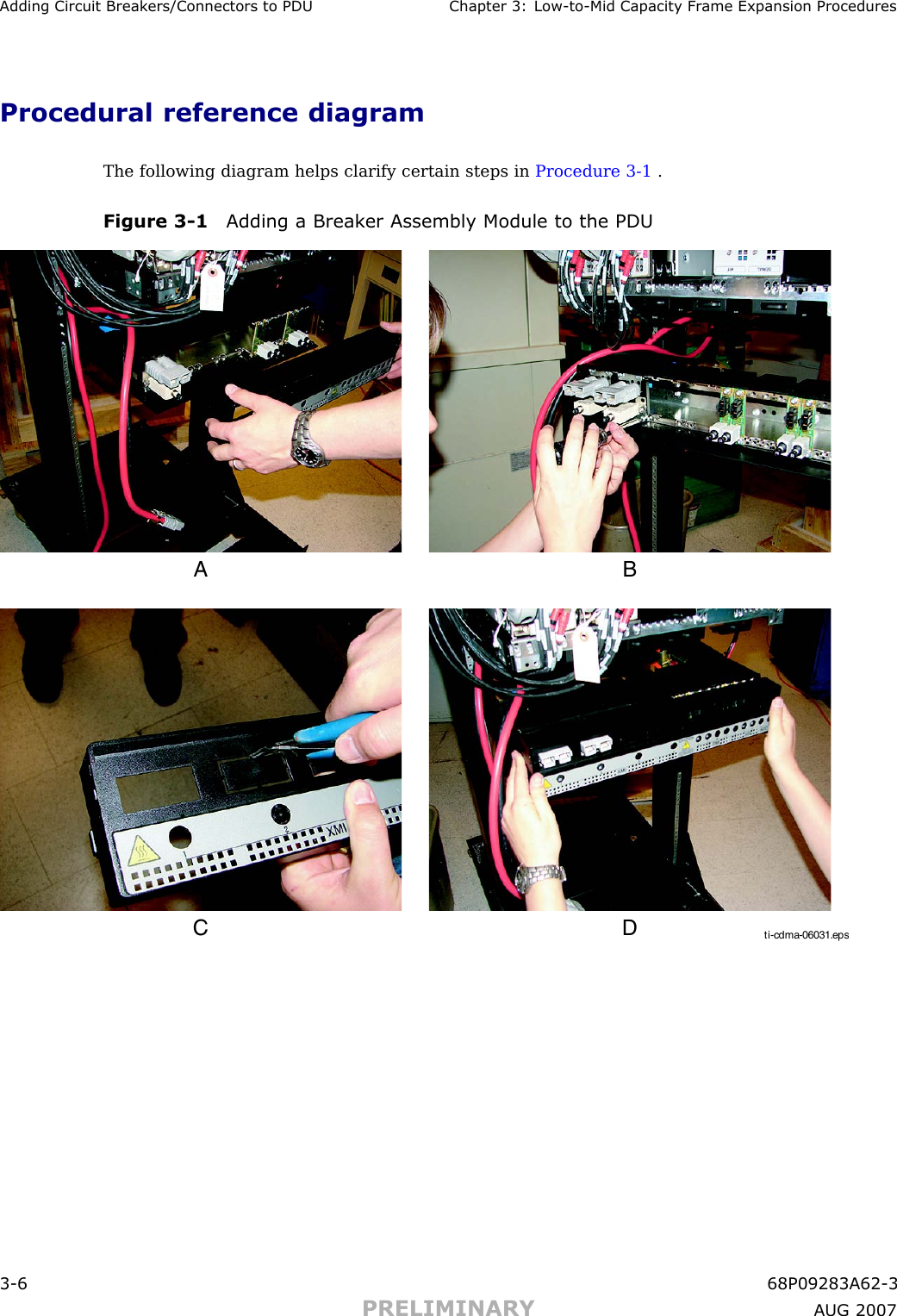
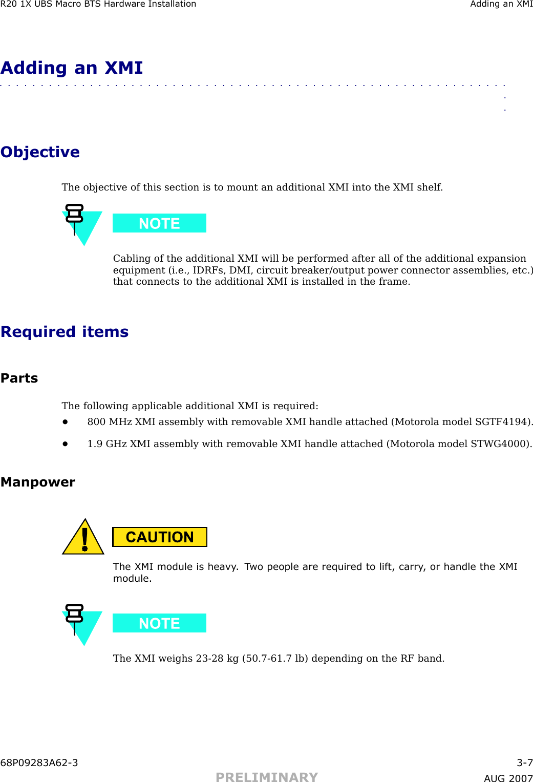
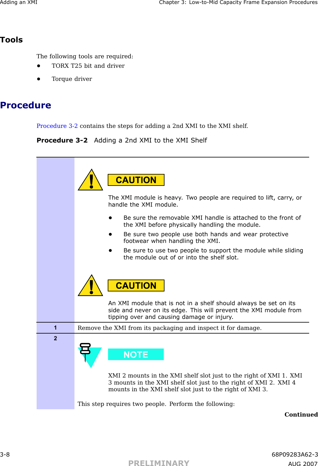
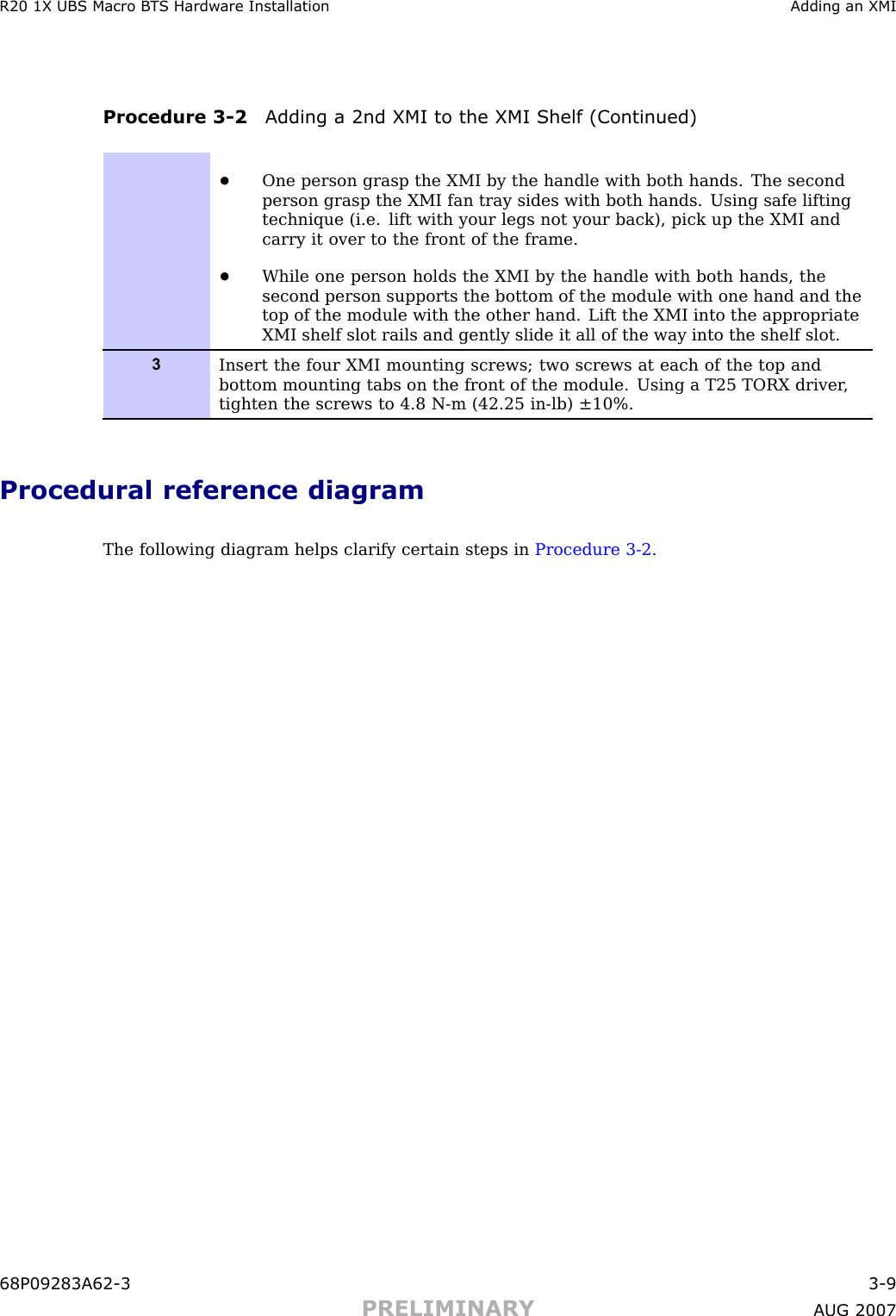
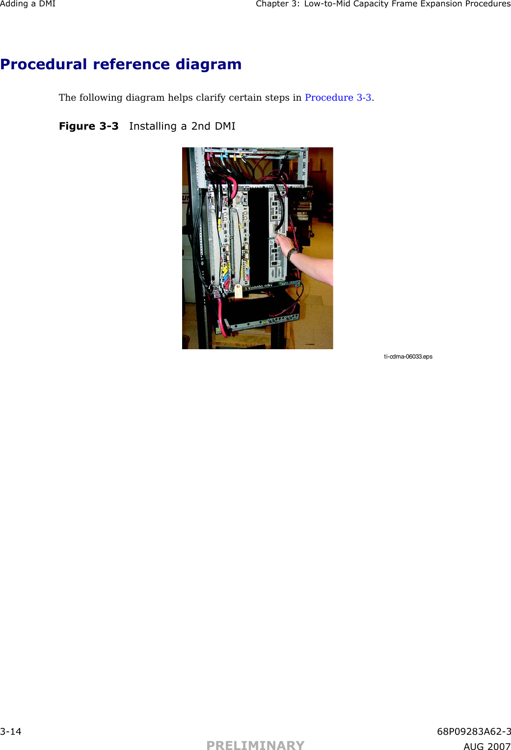
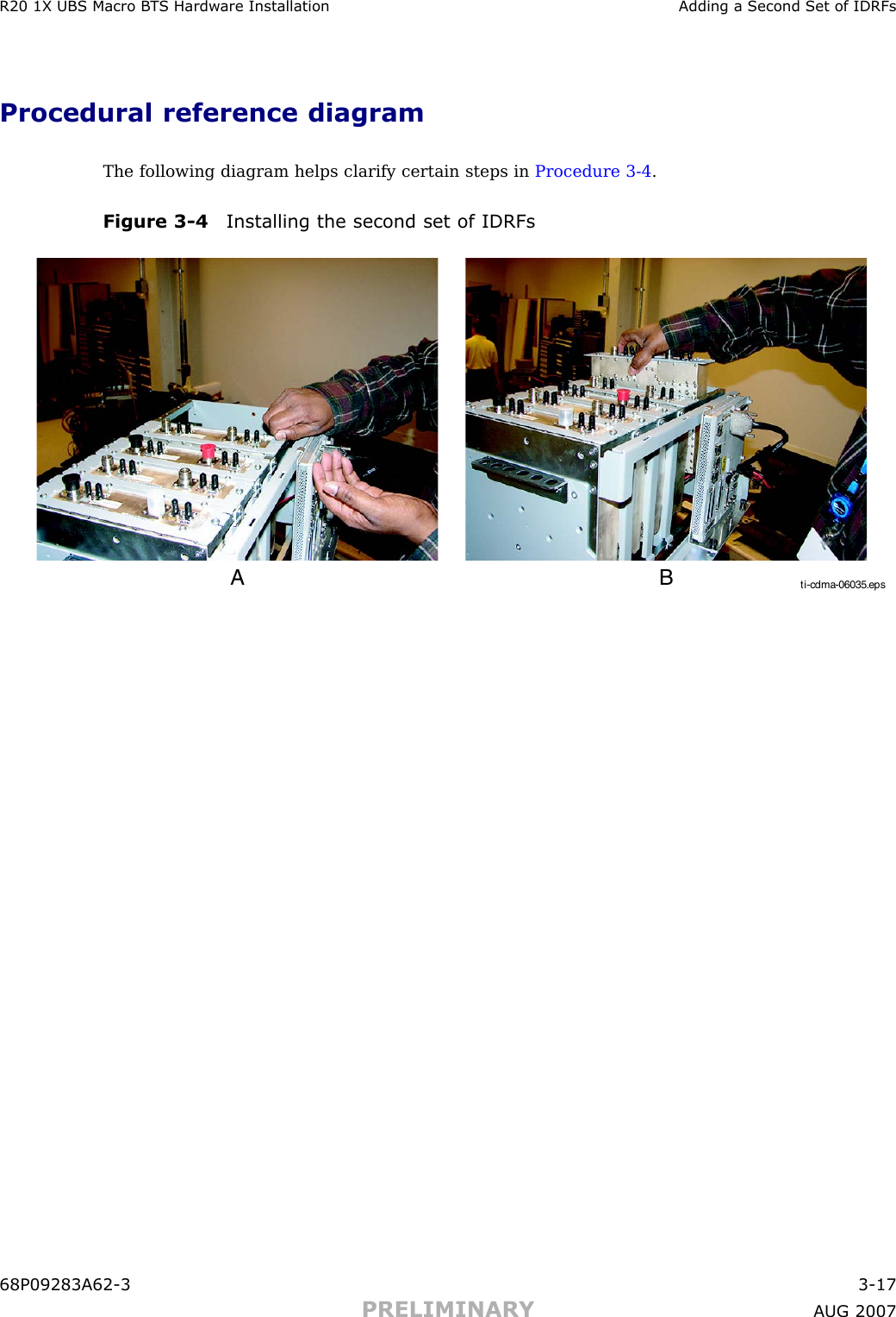
Exhibit 121b
Navigation menu
Upload a User Manual
Namespaces
Wiki Guide
HTML
PDF
Info
Views
User Manual
Discussion / Help
Navigation