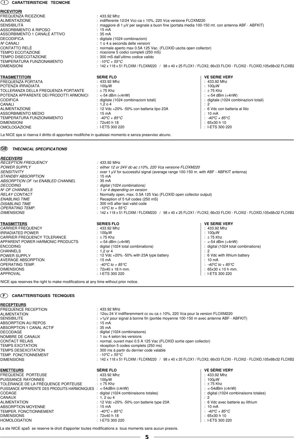
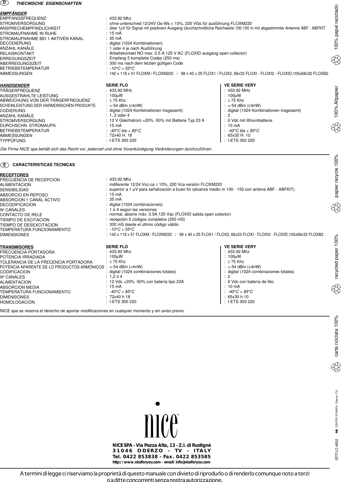
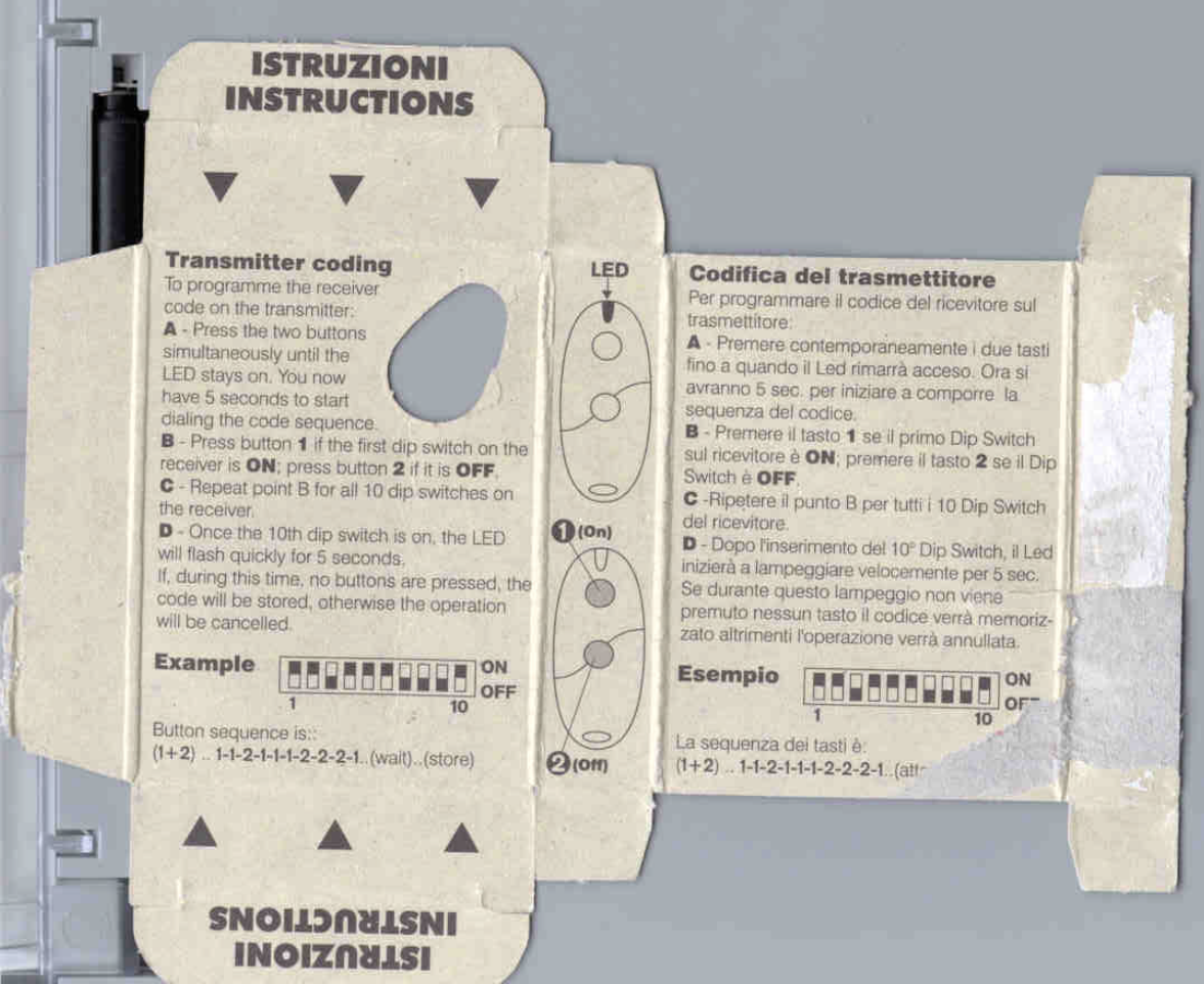
Nice S p A 433VR Transmitter User Manual users manual

Nice S.p.A. Transmitter users manual

users manual

     V. 005Radiocommandequartzeesérie FLO etVERYQuarzradio-controlseries FLO andVERYRadiocomandoquarzatoserie FLO eVERYQuarz-Funkssteuerungserie FLO undVERYMANUALEISTRUZIONIANLEITUNGS-HEFTINSTRUCTIONSMANUALRadiomandosde cuarzoserie FLO yVERYLIVRETD’INSTRUCTIONS MANUAL DEINSTRUCCIONESFGBI EDQUESTO LIBRETTO È  DESTINATO SOLO ALL'INSTALLATORE.L'installazione dovrà essere effettuata solamente da personale professionalmente qualificato in conformità a quanto previsto dalla legge n°46 del 5 marzo 1990 e successive modifiche ed integrazioni e nel pieno rispetto delle norme UNI 8612.
I GBFig. 1Fig. 2Fig. 3112 1234567810CH. 1CH. 1 CH. 2 CH. 3 CH. 4(FLOXM)10-18 V18-28 V“A”FLOXM220 = 220VacFLOXM = 12-24 Vcc/caCH. 1CH. 1CH. 110-18 V15-28 V12-24 Vca/cc CH2SEL. CHFLOX1FLOX2FLOXB2CH1“B”11234561210INDIRIZZO DEI CANALIADRESSAGE DES CANAUXDIRECCION DE LOS CANALESKANALACRESSIERUNG2nd CHANNEL TX3rd CHANNEL TX1st CHANNEL TX4th CHANNEL TXADDRESSING THE CHANNELDESCRIZIONE:I ricevitori serie FLO disponibili nella versioni mini ad innesto e a morsetti o nelle versionimodulari, permettono di controllare fino a 4 canali e possono essere abbinati ai trasmettitori ditipo FLO1, FLO2, FLO4 e VE della serie VERYLe versioni disponibili di ricevitori sono:Nei ricevitori serie FLOXM  FLOXM220 l’uscita dei canali viene effettuata tramite dei modulirelè opzionali di vario tipo che permettono di realizzare diverse funzioni:Modulo MXD canale impulsivo.Modulo MXP canale passo passo.Modulo MXT canale temporizzato da 3" a 5'. ( usare solo 2 moduli MXT in contemporanea).ISTRUZIONI PER L'INSTALLAZIONECome evidenziato sulla tabella, i ricevitori della serie FLO possono essere alimentati contensione di 24Vcc/ca o 220 Vca nella versione FLOXM220.Nelle versioni FLOX1, FLOX2, FLOXB2, la selezione della tensione viene fatta tramite ilponticello “B” (vedi fig. 2), che se inserito permette di alimentare la scheda ad una tensionedi 12 Vcc/ac, mentre nella versione FLOXM, la selezione della tensione viene eseguita tramiteil selettore “A” (vedi fig. 1) che se chiuso permette di alimentare la ricevente con una tensionedi 12 Vcc/ca mentre se aperto consente di alimentarla con una tensione di 24 Vcc/ac.Per evitare interferenze fra i ricevitori, installarli ad una distanza superiore a 50 cm.INSTALLAZIONE DELL'ANTENNAPer garantire il miglior funzionamento, ogni ricevitore della serie FLO deve essere installato conla propria antenna ABF o ABFKIT. L’antenna deve essere installata più in alto possibile, inpresenza di strutture metalliche o di muri in cemento armato, installare l’antenna al di sopra diquesti. Se il cavo dato in dotazione con l’antenna è troppo corto impiegare un cavo coassialecon impedenza 52 ohm (es.  RG58 a bassa perdita ), tale cavo non deve superare la lunghezzadi 10 mt. Nella versione FLOXM collegare la parte centrale (anima) al morsetto 2 e la calza almorsetto 1. Per le versioni FLOX1-FLOX2-FLOXB2-FLOXID la parte centrale va collegata almorsetto 2 e la calza al morsetto 1 (del morsetto a 2 posizioni).Nel caso non sia possibile installare l’antenna ABF o ABFKIT si possono ottenere dei discretirisultati usando come antenna uno spezzone di filo, montato disteso, della lunghezza di 18 cm.Tale spezzone va collegato al morsetto 2 per i ricevitori FLOXM-FLOXM220, o al morsetto 2sui ricevitori FLOX1 - FLOX2 - FLOXID - FLOXB2. Qualora l’antenna debba essere installatadove non ci sia un buon piano di terra (es. strutture murarie), è possibile collegare il morsettodella calza a terra (solo se nelle immediate vicinanze esiste una buona messa a terra)Ai ricevitori della serie FLO è possibile abbinare i trasmettitori della serie FLO ( FLO1, FLO2,FLO4) rispettivamente a 1 - 2 - 4 canali oppure i trasmettitori VE a 2 canali della serie VERY.COMPOSIZIONE DEI CODICI serie FLOI ricevitori ed i trasmettitori della serie FLO contengono 10 microinterruttori a 2 posizioni chevengono utilizzati per impostare il codice personalizzato.La composizione del codice deve essere la stessa sia per il ricevitore che per i trasmettitoriad esso legati.COMPOSIZIONE DEI CODICI serie VERYNei trasmettitori VE della serie VERY, i microinterruttori sono stati sostituiti con un sistema diprogrammazione che utilizza i due tasti del trasmettitore.Per eseguire la composizione del codice procedere nel seguente modo:1 - Premere contemporaneamente i due tasti sul trasmettitore fino a quando il Led rimarràacceso. Ora si avranno 5 sec. per iniziare a comporre la sequenza del codice.2 - Premere il tasto 1 se il primo microinterruttore sul ricevitore è ON, mentre premere il tasto2 se il microinterruttore è OFF.3 - Ripetere il punto 2 per tutti i 10 microinterruttori del ricevitore.4 - Dopo aver inserito il 10° microinterruttore il Led inizia a lampeggiare velocemente per 5 sec.Se durante questo lampeggio non viene premuto nessun tasto, il codice verrà memorizzato,altrimenti l’operazione verrà annullata. (Esempio vedi fig. 5)SELEZIONE DEI CANALINei ricevitori modulari FLOXM la selezione viene fatta con l’inserimento del modulo relè nelrispettivo canale, mentre per i ricevitori FLOX1 - FLOX2 - FLOXB2 - FLOX12 - FLOXID laselezione viene effettuata tramite l’inserimento di un ponticello (vedi fig. 3).Per i trasmettitori FLO1 - FLO2 l’associazione Tasto/Canale, se necessario può esseremodificata tramite una piccola goccia di stagno, la quale consente di indirizzare il segnale deitrasmettitore su uno dei 4 canali dei ricevitore (vedi fig.4).Per il trasmettitore FLO4 ogni tasto corrisponde al rispettivo canale del ricevitore.Nei trasmettitori VE della serie VERY, l’associazione Tasto/Canale non può essere modificata.In caso di cattivo funzionamento del trasmettitore verificare che la batteria non siascarica (per aprire il trasmettitore vedi fig. 6).Versione Alimentazione Connessioni Formato CanaliFLOXM 12/24 Vcc/ca Morsettiera Modulare Fino a 4FLOXM220 220 Vac Morsettiera Modulare Fino a 4FLOX1 12/24 Vcc/ca Morsettiera Box Mini 1FLOXI 12/24 Vcc/ca Innesto Scheda Mini 1FLOX2 12/24 Vcc/ca Morsettiera Box Mini 2FLOXB2 12/24 Vcc/ca Morsettiera Mini (IP53) 2FLOXI2 12/24 Vcc/ca Innesto Scheda Mini 2FLOXID 15 Vcc Scheda Mini 1Innesto DeutschDESCRIPTION:With the FLOFLOFLOFLOF L O receiver series - available in the mini plug-in and terminal or modular versions -up to 4 channels can be controlled and they can be associated with the FLO1, FLO2, FLO4FLO1, FLO2, FLO4FLO1, FLO2, FLO4FLO1, FLO2, FLO4FLO1, FLO2, FLO4 andVEVEVEVEV E type transmitters in the VERYVERYVERYVERYVERY series.The available receiver versions are:In the FLOXM  FLOXM220FLOXM  FLOXM220FLOXM  FLOXM220FLOXM  FLOXM220FLOXM  FLOXM220 receiver series, the output of the channels is done with differenttypes of optional relay modules with which different functions can be had:MXDMXDMXDMXDM X D module, pulse channel.MXPMXPMXPMXPM X P module, step-by-step channel.MXTMXTMXTMXTMXT module, timed channel from 3 seconds to 5 minutes. (use only 2 MXTMXTMXTMXTM X T  modules at the same time).INSTALLATION INSTRUCTIONSINSTALLATION INSTRUCTIONSINSTALLATION INSTRUCTIONSINSTALLATION INSTRUCTIONSINSTALLATION INSTRUCTIONSAs shown in the table the FLOFLOFLOFLOF L O receiver series can be powered with a voltage of 24Vdc/ac or220 Vac for the FLOXM220FLOXM220FLOXM220FLOXM220FLOXM220 version.In the FLOX1, FLOX2, FLOXB2FLOX1, FLOX2, FLOXB2FLOX1, FLOX2, FLOXB2FLOX1, FLOX2, FLOXB2FLOX1, FLOX2, FLOXB2 versions the voltage is selected with jumper “B”“B”“B”“B”“ B ” see Fig. 2Fig. 2Fig. 2Fig. 2Fig. 2which, if on, will allow the card to be powered at a voltage of 12 Vdc/ac. Voltage is selected forthe FLOXMFLOXMFLOXMFLOXMFLOXM version with the selector “A” (see Fig. 1)“A” (see Fig. 1)“A” (see Fig. 1)“A” (see Fig. 1)“A” (see Fig. 1) which, if closed, will allow the receiverto be powered at a voltage of 12 Vdc/ac and if open, with a voltage of 24 Vdc/ac.To avoid interference between receivers they must be installed more than 50 cm apart.To avoid interference between receivers they must be installed more than 50 cm apart.To avoid interference between receivers they must be installed more than 50 cm apart.To avoid interference between receivers they must be installed more than 50 cm apart.To avoid interference between receivers they must be installed more than 50 cm apart.INSTALLING THE AERIALINSTALLING THE AERIALINSTALLING THE AERIALINSTALLING THE AERIALINSTALLING THE AERIALTo guarantee optimum operation each receiver in the FLO FLO FLO FLO FLO series must be installed with its ownABFABFABFABFABF or ABFKITABFKITABFKITABFKITABFKIT aerial. This aerial should be installed as high as possible and if there are anymetal structures or reinforced concrete walls, install it above them. If the cable provided withthe aerial is too short use a coax with a 52 Ohm impedance (e.g. RG58 cable). This cable shouldbe no longer than 10 m. For the FLOXMFLOXMFLOXMFLOXMFLOXM version connect the central core to terminal 2 and theearth shield to terminal 1. For the FLOX1-FLOX2-FLOXB2-FLOXIDFLOX1-FLOX2-FLOXB2-FLOXIDFLOX1-FLOX2-FLOXB2-FLOXIDFLOX1-FLOX2-FLOXB2-FLOXIDFLOX1-FLOX2-FLOXB2-FLOXID versions connect thecentral part to terminal 2 and the braid to terminal 1 (of the 2-position terminal).If it is impossible to install the ABF or ABFKITABF or ABFKITABF or ABFKITABF or ABFKITABF or ABFKIT aerial, fairly good results can be had by usingan 18 cm long piece of wire as the aerial, laid flat and connected to terminal 2 (of the 2-positionterminal). If the aerial is installed in a place that is not connected to earth (e.g. masonrystructures) the shield’s terminal can be earthed (only if the earth point is in the immediate vicinityand of good quality).The transmitters of the FLO (FLO1, FLO2, FLO4)FLO (FLO1, FLO2, FLO4)FLO (FLO1, FLO2, FLO4)FLO (FLO1, FLO2, FLO4)FLO (FLO1, FLO2, FLO4) series can be used with the FLOFLOFLOFLOF L O receiverseries, 1-2-4 channels respectively, or the 2-channel VEVEVEVEV E transmitters in the VERYVERYVERYVERYVERY series.CODE COMPOSITION of the FLO seriesThe receivers and transmitters of the FLOFLOFLOFLOF L O series contain 10 2-position microswitches that areused to set the customised code.Code composition must be the same for the receiver and for the transmitters connected to itCODE COMPOSITION of the VERY seriesThe microswitches of VEVEVEVEV E in the VERYVERYVERYVERYVERY series transmitters have been substituted with aprogramming system that uses th e transmitter’s two keys.To compose the code proceed as follows:1 - Press the two keys on the transmitter at the same time until the LED stays on. You now have5 seconds to start composing the code sequence.2 - Press key 1 if the first microswitch on the receiver is ON; press key 2 if it is OFF.3 - Repeat point 2 for all the receiver’s 10 microswitches.4 - Once the 10th microswitch has been turned on, the LED will flash quickly for 5 seconds.If, while it is flashing, no keys are pressed,  the code will be stored otherwise the operationwill be cancelled.(See the example in Fig. 5)SELECTION OF THE CHANNELSSelection is made in the modular FLOXMFLOXMFLOXMFLOXMFLOXM receivers by plugging the relay module into therelative channel while  for the FLOX1 - FLOX2 - FLOXB2 - FLOX12 - FLOXIDFLOX1 - FLOX2 - FLOXB2 - FLOX12 - FLOXIDFLOX1 - FLOX2 - FLOXB2 - FLOX12 - FLOXIDFLOX1 - FLOX2 - FLOXB2 - FLOX12 - FLOXIDFLOX1 - FLOX2 - FLOXB2 - FLOX12 - FLOXID receivers,selection is made by plugging in a jumper (see Fig. 3)(see Fig. 3)(see Fig. 3)(see Fig. 3)(see Fig. 3).In the case of the FLO1 - FLO2FLO1 - FLO2FLO1 - FLO2FLO1 - FLO2FLO1 - FLO2 transmitters, the Key/Channel association can, if necessary,be modified with a small drop of tin, so the transmitter signal can be directed to one of the 4receiver channels (see Fig.4)(see Fig.4)(see Fig.4)(see Fig.4)(see Fig.4).For the FLO4FLO4FLO4FLO4FLO4 transmitter each key corresponds  to the relative receiver channel.On VEVEVEVEV E transmitters in the VERYVERYVERYVERYVERY series, the Key/Channel association cannot be modified.Should the transmitter malfunction, check that the battery has not run down (to open theShould the transmitter malfunction, check that the battery has not run down (to open theShould the transmitter malfunction, check that the battery has not run down (to open theShould the transmitter malfunction, check that the battery has not run down (to open theShould the transmitter malfunction, check that the battery has not run down (to open thetransmitter see Fig. 6).transmitter see Fig. 6).transmitter see Fig. 6).transmitter see Fig. 6).transmitter see Fig. 6).Version Power Connections Format ChannelsFLOXM 12/24 Vdc/ca Terminal board Modular Up to 4FLOXM220 220 Vac Terminal board Modular Up to 4FLOX1 12/24 Vdc/ca Terminal board Mini Box 1FLOXI 12/24 Vdc/ca Plug-in Mini Card 1FLOX2 12/24 Vdc/ca Terminal board Mini Box 2FLOXB2 12/24 Vdc/ca Terminal board Mini (IP53) 2FLOXI2 12/24 Vdc/ca Plug-in Mini Card 2FLOXID 15 Vdc Mini Card 1“Deutsch” Plug-in2
FDFig. 4DESCRIPTION:Les récepteurs série FLO disponibles dans les versions mini embrochable et à bornes oudans les versions modulaires, permettent de contrôler jusqu’à 4 canaux et peuvent être associésaux émetteurs type FLO1, FLO2, FLO4 et VE de la série VERY.Les versions de récepteurs disponibles sont les suivantes:Dans les récepteurs série FLOXM FLOXM220 la sortie des canaux s’effectue à travers desmodules relais de type divers qui permettent de réaliser différentes fonctions:Module MXD canal à impulsions.Module MXP canal pas-à-pas.Module MXT canal temporisé de 3” à 5’. (utiliser seulement 2 modules MXT simultanément).INSTRUCTIONS POUR L’INSTALLATIONComme l’indique le tableau, les récepteurs de la série FLO peuvent être alimentés avec unetension de 24Vcc/ca ou 220 Vca dans la version FLOXM220.Dans les versions FLOX1, FLOX2, FLOXB2, la sélection de la tension est effectuée à l’aide dushunt “B” (voir fig. 2), qui s’il est connecté permet d’alimenter la carte à une tension de 12 Vcc/ca, tandis que dans la version FLOXM, la sélection de la tension s’effectue à l’aide du sélecteur“A” (voir fig. 1) qui s’il est fermé permet d’alimenter le récepteur avec une tension de 12 Vcc/ca tandis que  quand il est ouvert il permet de l’alimenter avec une tension de 24 Vcc/ca.Pour éviter les interférences entre les récepteurs, les installer à une distance supérieureà 50 cm.INSTALLATION DE L’ANTENNEPour garantir le meilleur fonctionnement, chaque récepteur de la série FLO doit être installéavec sa propre antenne ABF ou ABFKIT. L’antenne doit être installée le plus haut possible,en présence de structures métalliques ou de murs en béton armé, installer l’antenne de manièrequ’elle dépasse ces structures. Si le câble fourni avec l’antenne est trop court, utiliser uncâble coaxial avec une imp0dance de 52 ohm (ex. RG58 à basse déperdition), ce câble nedoit pas dépasser 10 m. Dans la version FLOXM connecter la partie centrale (âme) à la borne2 et le conducteur externe (tresse) à la borne 1. Pour les versions FLOX1-FLOX2-FLOXB2-FLOXID la partie centrale doit être connectée à la borne 2 et le conducteur externe à la borne1 (de la borne à 2 positions).S’il n’est pas possible d’installer l’antenne ABF ou ABFKIT on peut obtenir de bons résultatsen utilisant comme antenne un bout de fil, monté à plat, de 18 cm de longueur, connecté à laborne 2 (de la borne à 2 positions). Si l’antenne doit être installée à un endroit dépourvu d’unebonne mise à la terre (par ex. structures en maçonnerie), il est possible de connecter la bornedu conducteur externe de l’antenne à la terre (seulement s’il existe une bonne mise à la terreàproximité immédiate).Les récepteurs de la série FLO peuvent être associés aux émetteurs de la série FLO (FLO1,FLO2, FLO4) respectivement à 1 - 2 - 4 canaux ou bien aux émetteurs VE à 2 canaux de lasérie VERY.COMPOSITION DES CODES série FLOLes récepteurs et les émetteurs de la série FLO contiennent 10 microinterrupteurs à 2 positionsqui sont utilisés pour programmer le code personnel.La composition du code doit être identique tant pour le récepteur que pour les émetteurs quilui sont associés.COMPOSITION DES CODES série VERYLes microinterrupteurs du VE de la série VERY ont été remplacés par un système deprogrammation qui utilise les deux touches de l’émetteur.Pour effectuer la composition du code, procéder de la façon suivante:1 - Presser simultanément les deux touches sur l’émetteur jusqu’à ce que la DEL reste allumée.À ce point on dispose de 5 s pour commencer à composer le code.2 - Presser la touche 1 si le premier microinterrupteur sur le récepteur est ON, et presser latouche 2 si le microinterrupteur est OFF.3 - Répéter le point 2 pour les 10 microinterrupteurs du récepteur.4 - Après avoir programmé le 10e microinterrupteur, la Led commence à clignoter rapidementpendant 5 secondes.Si aucune touche n’est pressée pendant ce clignotement, le code sera mémorisé, autrementl’opération sera annulée. (Exemple voir fig. 5)SÉLECTION DES CANAUXDans les récepteurs modulaires FLOXM la sélection est faite en embrochant le module relaisdans le canal respectif tandis que pour les récepteurs FLOX1 - FLOX2 - FLOXB2 - FLOX12- FLOXID la sélection est effectuée en connectant un shunt (voir fig. 3).Pour les émetteurs FLO1 - FLO2 l’association Touche/Canal peut être modifiée si nécessaireavec une petite goutte d’étain qui permet d’adresser le signal de l’émetteur sur l’un des 4canaux du récepteur (voir fig. 4).Pour l’émetteur FLO4 chaque touche correspond au canal correspondant du récepteur.L’association Touche/Canal ne peut pas être modifiée dans les émetteurs VE de la série VERY.En cas de mauvais fonctionnement de l’émetteur, vérifier que la pile n’est pas déchargée(pour ouvrir l’émetteur, voir fig. 6).Version Alimentation Connexions Format CanauxFLOXM 12/24 Vcc/ca Bornier Modulaire Jusqu’à 4FLOXM220 220 Vac Bornier Modulaire Jusqu’à 4FLOX1 12/24 Vcc/ca Bornier Box Mini 1FLOXI 12/24 Vcc/ca Embrochable Carte Mini 1FLOX2 12/24 Vcc/ca Bornier Box Mini 2FLOXB2 12/24 Vcc/ca Bornier Mini (IP53) 2FLOXI2 12/24 Vcc/ca Embrochable Carte Mini 2FLOXID 15 Vcc Carte Mini 1EmbrochableDeutschBESCHREIBUNG:Mit den Empfängern der Serie FLOFLOFLOFLOF LO, in den Ausführungen Mini zum Einstecken und mit Klemmenoder als modulare Empfänger zur Verfügung stehend, können bis zu 4 Kanäle kontrolliert werden;sie können mit den Sendern FLO1, FLO2, FLO4FLO1, FLO2, FLO4FLO1, FLO2, FLO4FLO1, FLO2, FLO4FLO1, FLO2, FLO4 und VEVEVEVEV E kombiniert werden aus der serie VERYVERYVERYVERYVERY.Die lieferbaren Empfängerversionen sind:Bei den Empfängern der Serie FLOXM FLOXM220FLOXM FLOXM220FLOXM FLOXM220FLOXM FLOXM220FLOXM FLOXM220 erfolgt der Ausgang der Kanäle durchRelaismodule (Sonderzubehör) verschiedener Art, mit denen unterschiedliche Funktionenerhalten werden können:Modul MXDMXDMXDMXDM X D Impulskanal.Modul MXPMXPMXPMXPM X P Kanal für Schrittbetrieb.Modul MXTMXTMXTMXTM XT Kanal mit Zeitgebung von 3" bis 5'. (nur 2 Module MXTMXTMXTMXTM XT gleichzeitig verwenden).INSTALLATIONSANWEISUNGENINSTALLATIONSANWEISUNGENINSTALLATIONSANWEISUNGENINSTALLATIONSANWEISUNGENINSTALLATIONSANWEISUNGENGemäß Tabelle, können die Empfänger der Serie FLOFLOFLOFLOFLO mit 24Vcc/ac oder mit 220 Vac Spannungin der Version FLOXM220FLOXM220FLOXM220FLOXM220FLOXM220 gespeist werden.Bei den Versionen FLOX1, FLOX2 und FLOXB2FLOX1, FLOX2 und FLOXB2FLOX1, FLOX2 und FLOXB2FLOX1, FLOX2 und FLOXB2FLOX1, FLOX2 und FLOXB2 erfolgt die Wahl der Spannung durch dieÜberbrückung “B” (siehe Abb. 2)“B” (siehe Abb. 2)“B” (siehe Abb. 2)“B” (siehe Abb. 2)“B” (siehe Abb. 2), mit der - falls eingeschaltet - die Karte mit 12 Vcc/acgespeist werden kann, wogegen bei der Version FLOXMFLOXMFLOXMFLOXMFLOXM die Wahl der Spannung durch denWählschalter “A” (siehe Abb. 1)“A” (siehe Abb. 1)“A” (siehe Abb. 1)“A” (siehe Abb. 1)“A” (siehe Abb. 1) ausgeführt wird, mit dem - falls geschlossen - der Empfängermit 12 Vcc/ac Spannung gespeist werden kann, und - falls geöffnet - mit  24 Vcc/ac.Um Interferenzen zwischen den Empfängern zu vermeiden, müssen sie mit einemUm Interferenzen zwischen den Empfängern zu vermeiden, müssen sie mit einemUm Interferenzen zwischen den Empfängern zu vermeiden, müssen sie mit einemUm Interferenzen zwischen den Empfängern zu vermeiden, müssen sie mit einemUm Interferenzen zwischen den Empfängern zu vermeiden, müssen sie mit einemAbstand von mehr als 50 cm installiert werden.Abstand von mehr als 50 cm installiert werden.Abstand von mehr als 50 cm installiert werden.Abstand von mehr als 50 cm installiert werden.Abstand von mehr als 50 cm installiert werden.INSTALLATION DER ANTENNEINSTALLATION DER ANTENNEINSTALLATION DER ANTENNEINSTALLATION DER ANTENNEINSTALLATION DER ANTENNEUm den besten Betrieb zu garantieren, muss jeder Empfänger der Serie FLOFLOFLOFLOF L O mit seiner An-tenne ABFABFABFABFA B F oder ABFKITABFKITABFKITABFKITABFKIT installiert werden. Die Antenne muss so hoch wie möglich installiertwerden; die Antenne bei Vorhandensein von Metallstrukturen oder Stahlbetonmauern überdiesen installieren. Sollte das mit der Antenne gelieferte Kabel zu kurz sein, ein Koaxialkabelmit 52 ohm Impedanz verwenden (z.B. RG58 mit niedrigem Verlust); dieses Kabel darf nichtlänger als 10 m sein. Für die Version FLOXMFLOXMFLOXMFLOXMFLOXM den zentralen Teil (Seele) mit Klemme 2 verbindenund das Geflecht mit Klemme 1. Für die Versionen FLOX1-FLOX2-FLOXB2-FLOXIDFLOX1-FLOX2-FLOXB2-FLOXIDFLOX1-FLOX2-FLOXB2-FLOXIDFLOX1-FLOX2-FLOXB2-FLOXIDFLOX1-FLOX2-FLOXB2-FLOXID mussder zentrale Teil mit Klemme 2 und das Geflecht mit Klemme 1 (der 2-stelligen Klemme)verbunden werden.Sollte die Installation der Antenne ABF oder ABFKITABF oder ABFKITABF oder ABFKITABF oder ABFKITABF oder ABFKIT nicht möglich sein, können auch miteinem 18 cm langem, geradlinig montiertem Stück Draht als Antenne, das an die Klemme 2(der zweistelligen Klemme) angeschlossen wird, diskrete Ergebnisse erhalten werden. Solltedie Antenne an einem Ort installiert werden müssen, wo keine gute Erdung besteht (z.B.Mauern), kann die Klemme des Geflechts geerdet werden (nur falls in unmittelbarer Näheeine gute Erdung besteht).Mit den Empfängern der Serie FLOFLOFLOFLOFL O kann man die Sender der Serie FLO (FLO1, FLO2, FLO4)FLO (FLO1, FLO2, FLO4)FLO (FLO1, FLO2, FLO4)FLO (FLO1, FLO2, FLO4)FLO (FLO1, FLO2, FLO4)jeweils mit 1 - 2 - 4 Kanälen oder die 2 Kanälen sender VEVEVEVEV E aus serie VERYVERYVERYVERYVERY kombinieren.ZUSAMMENSETZUNG DER CODES - Serie FLOZUSAMMENSETZUNG DER CODES - Serie FLOZUSAMMENSETZUNG DER CODES - Serie FLOZUSAMMENSETZUNG DER CODES - Serie FLOZUSAMMENSETZUNG DER CODES - Serie FLODie Empfänger und Sender der Serie FLO enthalten 10 2-stellige Mikroschalter, die zur Eingabedes individuellen Codes benutzt werden.Die Zusammensetzung des Codes mussmussmussmussmuss sowohl für den Empfänger als auch die mit ihmverbundenen Empfänger die gleiche sein.ZUSAMMENSETZUNG DER CODES - Serie VERYZUSAMMENSETZUNG DER CODES - Serie VERYZUSAMMENSETZUNG DER CODES - Serie VERYZUSAMMENSETZUNG DER CODES - Serie VERYZUSAMMENSETZUNG DER CODES - Serie VERYBei den Sendern der Serie VEVEVEVEV E aus der serie VERYVERYVERYVERYVERY sind die Mikroschalter mit einemProgrammierungssystem ersetzt worden, das die zwei Tasten des Senders ausnutzt.Für die Zusammensetzung des Codes wie folgt vorgehen:1 - Gleichzeitig die zwei Sendertasten drücken, bis die Led eingeschaltet bleibt. Nun hat man5 Sekunden Zeit, um mit der Zusammensetzung der Codesequenz zu beginnen.2 - Die Taste 1 drücken, falls der erste Mikroschalter am Empfänger auf ON gestellt ist; fallser auf OFF ist, die Taste 2 drücken.3 - Punkt 2 an allen 10 Mikroschaltern des Empfängers wiederholen.4 - Nach Einschaltung des 10. Mikroschalters, wird die Led 5 Sekunden lang schnell blinken.Wird während dieses Blinkens keine Taste gedrückt, so wird der Code gespeichert,andernfalls wird der Vorgang annulliert (als Beispiel siehe Abb. 5)WAHL DER KANÄLEWAHL DER KANÄLEWAHL DER KANÄLEWAHL DER KANÄLEWAHL DER KANÄLEBei den modularen Empfängern FLOXMFLOXMFLOXMFLOXMFLOXM erfolgt die Wahl durch die Einschaltung desRelaismoduls in den entsprechenden Kanal, wogegen sie bei den Empfängern FLOX1 - FLOX2FLOX1 - FLOX2FLOX1 - FLOX2FLOX1 - FLOX2FLOX1 - FLOX2- FLOXB2 - FLOX12 - FLOXID- FLOXB2 - FLOX12 - FLOXID- FLOXB2 - FLOX12 - FLOXID- FLOXB2 - FLOX12 - FLOXID- FLOXB2 - FLOX12 - FLOXID durch die Einschaltung einer Überbrückung erfolgt (siehe(siehe(siehe(siehe(sieheAbb. 3)Abb. 3)Abb. 3)Abb. 3)Abb. 3).Für die Sender FLO1 - FLO2FLO1 - FLO2FLO1 - FLO2FLO1 - FLO2FLO1 - FLO2 kann die Kombination Taste/Kanal gegebenenfalls mit einemTropfen Zinn geändert werden, der es gestattet, das Signal der Sender auf einen der 4 Kanäledes Empfängers auszurichten (siehe Abb.4)(siehe Abb.4)(siehe Abb.4)(siehe Abb.4)(siehe Abb.4).Beim Sender FLO4 entspricht jede Taste dem jeweiligen Empfängerkanal.Bei den Sendern VE VE VE VE VE  aus der Serie VERYVERYVERYVERYVERY kann die Kombination Taste/Kanal nicht geändertwerden.Falls der Sender nicht korrekt funktioniert, prüfen, ob die Batterie leer ist (siehe Abb. 6,Falls der Sender nicht korrekt funktioniert, prüfen, ob die Batterie leer ist (siehe Abb. 6,Falls der Sender nicht korrekt funktioniert, prüfen, ob die Batterie leer ist (siehe Abb. 6,Falls der Sender nicht korrekt funktioniert, prüfen, ob die Batterie leer ist (siehe Abb. 6,Falls der Sender nicht korrekt funktioniert, prüfen, ob die Batterie leer ist (siehe Abb. 6,um den Sender zu öffnen).um den Sender zu öffnen).um den Sender zu öffnen).um den Sender zu öffnen).um den Sender zu öffnen).Version Speisung Verbindungen Format KanäleFLOXM 12/24 Vcc/ca Klemmenbrett modular bis 4FLOXM22 220 Vac Klemmenbrett modular bis 4FLOX1 12/24 Vcc/ca Klemmenbrett Mini-Box 1FLOXI 12/24 Vcc/ca Steckverbindung Mini-Karte 1FLOX2 12/24 Vcc/ca Klemmenbrett Mini-Box 2FLOXB2 12/24 Vcc/ca Klemmenbrett Mini (IP53) 2FLOXI2 12/24 Vcc/ca Steckverbindung Mini-Karte 2FLOXID 15 Vcc Mini-Karte 1DeutscheSteckverbindung3INDIRIZZO DEI CANALIADDRESSING THE CHANNELADRESSAGE DES CANAUXKANALADRESSIERUNGDIRECCION DE LOS CANALES 1° Ch Rx2° Ch Rx3° Ch Rx 1°Ch Tx-1°Ch Rx2°Ch Tx-3°Ch Rx1°Ch Tx-3°Ch Rx2°Ch Tx-2°Ch Rx1°Ch Tx-1°Ch Rx2°Ch Tx-4°Ch Rx1°Ch Tx-3°Ch Rx2°Ch Tx-4°Ch Rx1°Ch Tx-1°Ch Rx2°Ch Tx-2°Ch Rx1°Ch Tx-4°Ch Rx2°Ch Tx-2°Ch Rx4° Ch RxTX 1 Ch TX 2 Ch=  Saldatura - Welding - Soudure - Schweissung - Soldatura X = Taglio - Cut - Coupe - Schnitt - CorteAFGEHBABABFEGHFEGHFEGHFEGHFEGHFEGHABAB
EDESCRIPCIÓN:Los receptores de la serie FLO, disponibles en las versiones mini con terminal de bayonetay con terminal de borne, o en las versiones modulares, permiten controlar hasta 4 canalesy se pueden combinar con los transmisores de tipo FLO1, FLO2, FLO4 y VE de la serieVERY Las versiones disponibles de receptores son:En los receptores de la serie FLOXM  FLOXM220 la salida de los canales se efectüa pormedio de los módulos rel0 opcionales de varios tipos, que permiten realizar diferentesfunciones:Módulo MXD canal impulsivo.Módulo MXP canal paso a paso.Módulo  MXT canal temporizado desde 3" a 5'. (use sólo 2 müdulos MXTcontemporáneamente).INSTRUCCIONES PARA LA INSTALACIÓNComo evidenciado en la tabla, los receptores de la serie FLO pueden estar alimentadoscon tensión de 24Vcc/ca o 220 Vca en la versión FLOXM220.En las versiones FLOX1, FLOX2, FLOXB2, la selección de la tensión se realiza a travésde la conexión puente “B” (véase fig. 2), que si se conecta, permite alimentar la tarjetacon una tensión de 12 Vcc/ca, mientras que en la versión FLOXM, la selección de latensión se efectúa por medio del selector “A” (véase fig. 1), que si está cerrado, permitealimentar la tarjeta con una tensión de Vcc/ca, mientras que si está abierto permitealimentarla con una tensión de 24 Vcc/ca.Para evitar interferencias entre los receptores, instálelos a más de 50 cm.INSTALACIÓN DE LA ANTENAPara garantizar el mejor funcionamiento, cada receptor de la serie FLO se tiene queinstalar con su antena ABF o ABFKIT. La antena se tiene que instalar lo más alta posible;ante la presencia de estructuras metálicas o paredes de cemento armado, instale laantena por encima de las mismas. Si el cable suministrado con la antena es muy corto,utilice un cable coaxial con impedancia 52 ohm (por ej. RG58 de baja pérdida); dicho cableno tiene que superar 10 metros. En la versión FLOXM conecte la parte central (alma) alborne 2 y la trenza al borne 1. Para las versiones FLOX1-FLOX2-FLOXB2-FLOXID laparte central se conecta al borne 2 y la trenza al borne 1 (del borne de 2 posiciones).Si no es posible instalar la antena ABF o ABFKIT, se pueden obtener resultados discretosusando como antena un pedazo de cable de 18 cm, montado extendido. Dicho cable seconecta al borne 2 (del borne de 2 posiciones). Si la antena se tiene que instalar en dondeno hay una buena puesta a tierra (por ej. paredes) se puede conectar el borne de la trenzaa tierra (sólo si en las cercanÌas hay una buena conexión a tierra)A los receptores de la serie FLO se les pueden combinar los transmisores de la serie FLO( FLO1, FLO2, FLO4 ) de 1 - 2 - 4 canales respectivamente, o los transmisores VE de 2canales de la serie VERY.COMPOSICIÓN DE LOS CÓDIGOS serie FLOLos receptores y transmisores de la serie FLO tienen 10 microinterruptores de 2posiciones, que se usan para introducir el código personalizado.La composición del código tiene que ser la misma tanto para el receptor como para lostransmisores que están conectados al mismo.COMPOSICIÓN DE LOS CÓDIGOS serie VERYEn los transmisores VE de la serie VERY, los microinterruptores han sido sustituidos conun sistema de programación que usa las dos teclas del transmisor.Para efectuar la composición del código, actúe de la siguiente manera:1 - Pulse contemporáneamente las dos teclas del transmisor, hasta que el Led quedeencendido. Entonces dispondrá de 5 seg. para empezar a componer la secuencia delcódigo.2 - Pulse la tecla 1 si el primer microinterruptor en el receptor está en ON, y pulse la tecla2 si el microinterruptor están en OFF.3 - Repita el punto 2 para los 10 microinterruptores del receptor.4 - Tras haber introducido el 10° microinterruptor, el Led empieza a parpadear rápidamentepor 5 seg.Si durante dicho parpadeo no se pulsa ninguna tecla, el código se memorizará, en casocontrario se anula la operación (para el ejemplo, véase la fig. 5).SELECCIÓN DE LOS CANALESEn los receptores modulares FLOXM, la selección se realiza conectando el módulo relé enel canal correspondiente, mientras que para los receptores FLOX1 - FLOX2 - FLOXB2 -FLOX12 - FLOXID, la selección se efectúa realizando una conexión puente (véase fig. 3).Para los transmisores FLO1 - FLO2 la asociación Tecla/Canal se puede modificar pormedio de una pequeña gota de estaño, la cual permite dirigir la señal de los transmisoreshacia uno de los 4 canales del receptor (véase fig.4).Para el transmisor FLO4, cada tecla corresponde al respectivo canal del receptor.En los transmisores VE de la serie VERY, la asociación Tecla/Canal no se puedemodificar.En el caso de que el transmisor no funcione bien, controle que la baterÌa no estédescargada (para abrir el transmisor, véase fig. 6).Versión Alimentatión Conexiones Formato CanalesFLOXM 12/24 Vcc/caTerminal de borneModular Hasta 4FLOXM220 220 VacTerminal de borneModular Hasta 4FLOX1 12/24 Vcc/caTerminal de borneBox Mini 1FLOXI 12/24 Vcc/ca Terminal debayoneta Tarjeta Mini 1FLOX2 12/24 Vcc/caTerminal de borneBox Mini 2FLOXB2 12/24 Vcc/caTerminal de borneMini (IP53) 2FLOXI2 12/24 Vcc/ca Terminal debayoneta Tarjeta Mini 2FLOXID 15 Vcc Tarjeta Mini 1Terminal debayoneta Deutsch4Fig. 5Fig. 6Fig. 7Fig. 8RICEVITORE FLOXB2RECEIVER FLOXB2RECEPTEURS FLOXB2EMPFÄNGER FLOXB2RECEPTOR FLOXB2RICEVITORE FLOXMRECEIVER FLOXMRECEPTEURS FLOXMEMPFÄNGER FLOXMRECEPTOR FLOXMRICEVITORE FLOX1 - FLOX2RECEIVER FLOX1 - FLOX2RECEPTEURS FLOX1 - FLOX2EMPFÄNGER FLOX1 - FLOX2RECEPTOR FLOX1 - FLOX2FLOVery VE( On )( Off )PROGRAMMAZIONEPROGRAMMINGPROGRAMMATIONPROGRAMIERUNGPROGRAMACIÓNOnOff110211+2 ..... 1 - 1- 2- 1- 1- 1- 2- 2- 2- 1
La ste NICE spa5  se reserve le droit d'apporter toutes modifications a  tous moments sans aucun preavis.           CARATTERISTICHE   TECNICHERICEVITORIFREQUENZA RICEZIONEALIMENTAZIONESENSIBILITÀASSORBIMENTO A RIPOSOASSORBIMENTO 1 CANALE ATTIVODECODIFICANo CANALICONTATTO RELÈTEMPO ECCITAZIONETEMPO DISECCITAZIONETEMPERATURA FUNZIONAMENTODIMENSIONITRASMETTITORIFREQUENZA PORTATAPOTENZA IRRADIATATOLLERANZA DELLA FREQUENZA PORTANTEPOTENZA APPARENTE DEI PRODOTTI ARMONICICODIFICACANALIALIMENTAZIONEASSORBIMENTO MEDIOTEMPERATURA FUNZIONAMENTODIMENSIONIOMOLOGAZIONEI:433.92 MHz: either 12 or 24V dc-ac ±10%, 220 Vca versione FLOXM220:over 1 µV for successful signal (average range 100-150 m. with ABF - ABFKIT antenna):15 mA: 35 mA: digital (1024 combinations): 1 or 4 depending on version:Normally open, max. 0.5A 125 Vac (FLOXID open collector output):Reception of 5 full codes (250 mS): 300 mS after last valid code:-10°C to + 55°C:142 x 118 x 51 FLOXM / FLOXM220   /   98 x 40 x 25 FLOX1 / FLOX2, 66x33 FLOXI - FLOXI2 - FLOXID,105x68x32 FLOXB2SERIES FLO VE SERIE VERY: 433.92 Mhz : 433.92 Mhz: 100µW : 100µW:± 75 Khz : ± 75 Khz: <-54 dBm (<4nW) : <-54 dBm (<4nW): digital (1024 total combinations) : digital (1024 total combinations): 1,2 or 4 : 2: 12 Vdc +20% -50% with 23A type battery : 6 Vdc with lithium battery: 15 mA : 10 mA:-40°C to + 85°C:-40°C to + 85°C: 72x40 x 18 h mm. : 65x30 x 10 h mm.: I-ETS 300 220 : I-ETS 300 220: 433.92 Mhz: indifferente 12/24 Vcc-ca ± 10%, 220 Vca versione FLOXM220: maggiore di 1 µV per segnale a buon fine (portata media 100-150 mt. con antenna ABF - ABFKIT): 15 mA: 35 mA: digitale (1024 combinazioni): 1 o 4 a seconda delle versioni: normale aperto max 0.5A 125 Vac. (FLOXID uscita open collector): ricezione 5 codici completi (250 mS): 300 mS dall’ultimo codice valido:-10°C + 55°C:142 x 118 x 51 FLOXM / FLOXM220   /   98 x 40 x 25 FLOX1 / FLOX2, 66x33 FLOXI - FLOXI2 - FLOXID,105x68x32 FLOXB2SERIE FLO VE SERIE VERY: 433.92 Mhz : 433.92 Mhz: 100µW : 100µW:± 75 Khz : ± 75 Khz: <-54 dBm (<4nW) : <-54 dBm (<4nW): digitale (1024 combinazioni totali) : digitale (1024 combinazioni totali): 1,2 o 4 : 2: 12 Vdc +20% -50% con batteria tipo 23A : 6 Vdc con batteria al litio: 15 mA : 10 mA:-40°C + 85°C:-40°C + 85°C: 72x40 h 18 : 65x30 h 10: I-ETS 300 220 : I-ETS 300 220           CARATTERISTIQUES  TECNIQUESRECEPTEURSFREQUENCE RECEPTIONALIMENTATIONSENSIBILITEABSORPTION AU REPOSABSORPTION 1 CANAL ACTIFDECODAGENOMBRE DE CANAUXCONTACT RELAISTEMPS EXCITATIONTEMPS DESEXCITATIONTEMP. FONCTIONNEMENTDIMENSIONSEMETTEURSFREQUENCE  PORTEUSEPUISSANCE RAYONNEETOLÈRANCE DE LA FRÉQUENCE PORTEUSEPUISSANCE APPARENTE DES PRODUITS HARMONIQUESCODAGECANAUXALIMENTATIONABSORPTION MOYENNETEMPER. FONCTIONNEMENTDIMENSIONSHOMOLOGATIONNICE spa reserves the right to make modifications at any time without prior notice.           THECNICAL SPECIFICATIONSRECEIVERSRECEPTION FREQUENCYPOWER SUPPLYSENSITIVITYSTANDBY ABSORPTIONABSORPTION OF 1st ENABLED CHANNELDECODINGNo OF CHANNELSRELAY CONTACTENABLING TIMEDISABLING TIMEOPERATING TEMP.DIMENSIONSTRASMITTERSCARRIER FREQUENCYIRRADIATED POWERCARRIER FREQUENCY TOLERANCEAPPARENT POWER HARMONIC PRODUCTSENCODINGCHANNELSPOWER SUPPLYAVERAGE ABSORPTIONOPERATING TEMP.DIMENSIONSAPPROVALGBF: 433.92 MHz: 12ou 24 V indifferemment cc ou ca ± 10%, 220 Vca pour la version FLOXM220:>1µV pour signal à bonne fin (portée moyenne 100-150 m avec antenne ABF - ABFKIT): 15 mA: 35 mA: digital (1024 combinaisons): 1 ou 4 selon les versions: normal. ouvert maxi 0.5 A 125 Vac (FLOXID sortie open collector): réception 5 codes complets (250 ms): 300 ms à partir du dernier code valable:-10°C + 55°C:142 x 118 x 51 FLOXM / FLOXM220   /   98 x 40 x 25 FLOX1 / FLOX2, 66x33 FLOXI - FLOXI2 - FLOXID,105x68x32 FLOXB2SÈRIE FLO VE SÈRIE VERY: 433.92 Mhz : 433.92 Mhz: 100µW : 100µW:± 75 Khz : ± 75 Khz: <-54dBm (≤4nW) : <-54dBm (≤4nW): digital (1024 combinaisons totales) : digital (1024 combinaisons totales): 1, 2 ou 4 : 2: 12 Vdc +20% -50% con batterie type 23A : 6 Vdc avec batterie au lithium: 15 mA : 10 mA:-40°C + 85°C:-40°C + 85°C: 72x40 h 18 : 65x30 h 10: I-ETS 300 220 : I-ETS 300 220La NICE spa si riserva il diritto di apportare modifiche in qualsiasi momento e senza preavviso alcuno.5
: 433.92 Mhz: ohne unterschied 12/24V Gs-Ws ± 10%, 220 VGs für ausführung FLOXM220:über 1µV für Signal mit positivem Ausgang (durchschnittliche Reichweite 100-150 m mit abgestimmter Antenne ABF - ABFKIT: 15 mA: 35 mA: digital (1024 Kombinationen): 1 oder 4 je nach Ausführung: Arbeitskontakt NO max. 0.5 A 125 V AC (FLOXID ausgang open collector): Empfang 5 komplette Codes (250 ms): 300 ms nach dem letzten gültigen Code:-10°C + 55°C:142 x 118 x 51 FLOXM / FLOXM220   /   98 x 40 x 25 FLOX1 / FLOX2, 66x33 FLOXI - FLOXI2 - FLOXID,105x68x32 FLOXB2SERIE FLO VE SERIE VERY: 433.92 MHz : 433.92 MHz: 100µW : 100µW:± 75 Khz : ± 75 Khz: <-54 dBm (≤4nW) : <-54 dBm (≤4nW): digital (1024 Kombinationen insgesamt) : digital (1024 Kombinationen insgesamt): 1, 2 oder 4 : 2: 12 V Gleichstrom +20% -50% mit Batterie Typ 23 A : 6 Vdc mit lithiumbatterie: 15 mA : 10 mA:-40°C bis + 85°C:-40°C bis + 85°C: 72x40 H. 18 : 65x30 H. 10: I-ETS 300 220 : I-ETS 300 220              THECNISCHE  EIGENSCHAFTENEMPFÄNGEREMPFANGSFREQUENZSTROMVERSORGUNGANSPRECHEMPFINDLICHKEITSTROMAUFNAHME IN RUHESTROMAUFNAHME BEI 1 AKTIVEN KANALDECODIERUNGANZAHL KANÂLERELAISKONTAKTERREGUNGSZEITABERREGUNGSZEITBETRIEBSTEMPERATURABMESSUNGENHANDSENDERTRÄGERFREQUENZAUSGESTRAHLTE LEISTUNGABWEICHUNG VON DER TRÄGERFREQUENZSCHEINLEISTUNG DER HARMONISCHEN PRODUKTECODIERUNGANZAHL KANÄLESTROMVERSORGUNGDURCHSCHN. STROMAUFN.BETRIEBSTEMPERATURABMESSUNGENTYPPÜFUNGDie Firma NICE spa behält sich das Recht vor, jederzeit und ohne Vorankündigung Veränderungen durchzuführen.D           CARACTERISTICAS TECNICASRECEPTORESFRECUENCIA DE RECEPCIONALIMENTACIONSENSIBILIDADABSORCIO EN REPOSOABSORCION 1 CANAL ACTIVODECODIFICACIONNo CANALESCONTACTO DE RELETIEMPO DE EXCITACIONTIEMPO DE DESEXCITACIONTEMPERATURA FUNCIONAMIENTODIMENSIONESTRANSMISORESFRECUENCIA PORTADORAPOTENCIA IRRADIADATOLERANCIA DE LA FRECENCIA PORTADORAPOTENCIA APARENTE DE LO PRODUCTOS ARMÓNICOSCODIFICACIONNo CANALESALIMENTACIONABSORCION MEDIATEMPERATURA FUNCIONAMIENTODIMENSIONESHOMOLOGACIÓNEA termini di legge ci riserviamo la proprietà di questo manuale con divieto di riprodurlo o di renderlo comunque noto a terzio a ditte concorrenti senza nostra autorizzazione.NICE SPA - Via Pezza Alta, 13 - Z.I. di Rustignè31046 ODERZO - TV - ITALYTel. 0422 853838 - Fax. 0422 853585http://www.niceforyou.com - email: info@niceforyou.comNICE spa se reserva el derecho de aportar modificaciones en cualquier momento y sin aviso previo.carta riciclata 100% recycled paper 100% papier recycle 100% 100% Altpapier 100% papel recicladoISTFLO 4852CENTRO STAMPA - Oderzo (TV): 433.92 Mhz: indiferente 12/24 Vcc-ca ± 10%, 220 Vca versión FLOXM220: superior a 1 µV para señalización a buen fin (alcance medio m 100 - 150 con antena ABF - ABFKIT): 15 mA: 35 mA: digital (1024 combinaciones): 1 ó 4 según las versiones: normal, abierto máx. 0.5A 125 Vac (FLOXID salida open colector): recepción 5 códigos completos (250 mS): 300 mS desde el último código válido:-10°C + 55°C:142 x 118 x 51 FLOXM / FLOXM220   /   98 x 40 x 25 FLOX1 / FLOX2, 66x33 FLOXI - FLOXI2 - FLOXID,105x68x32 FLOXB2SERIE FLO VE SERIE VERY: 433.92 Mhz : 433.92 Mhz: 100µW : 100µW:± 75 Khz : ± 75 Khz: <-54 dBm (<4nW) : <-54 dBm (<4nW): digital (1024 combinaciones totales) : digital (1024 combinaciones totales): 1,2 ó 4 : 2: 12 Vdc +20% -50% con batería tipo 23A : 6 Vdc con batería de litio: 15 mA : 10 mA:-40°C + 85°C:-40°C + 85°C: 72x40 h 18 : 65x30 h 10: I-ETS 300 220 : I-ETS 300 220
This device complies with Part 15 of the FCC Rules.Operation is subject to the following two conditions:(1)  this device may not cause harmful interference,and (2)  this device must accept any interferencereceived, including interference that may causeundesired operation.  Any changes or modificationsmade to this device without the express permissionof the manufacturer may void the user's authority tooperate this device.

Navigation menu