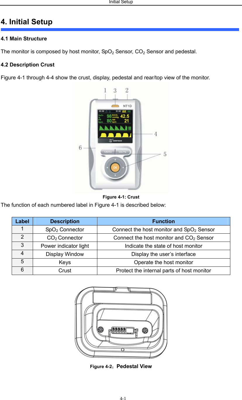
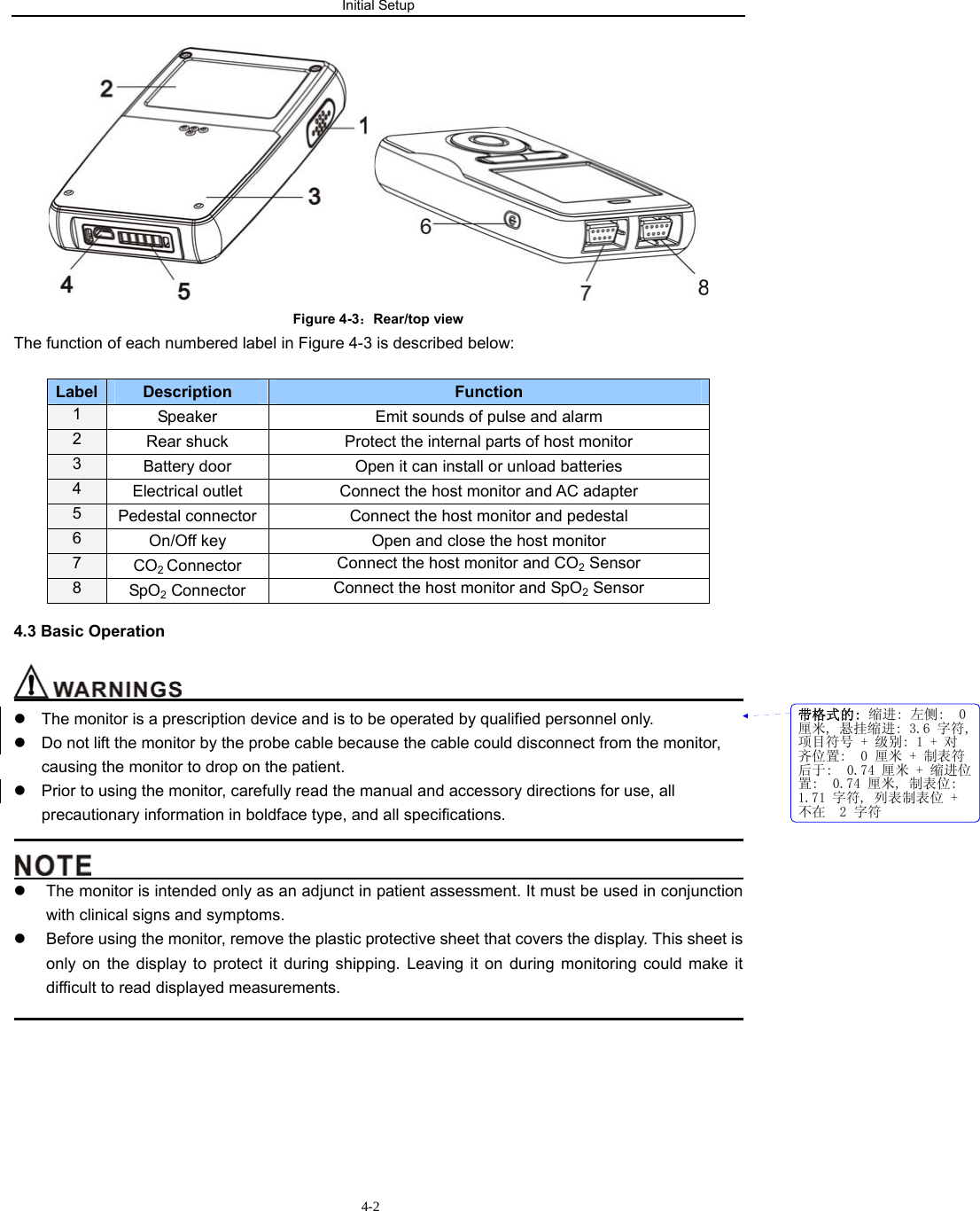
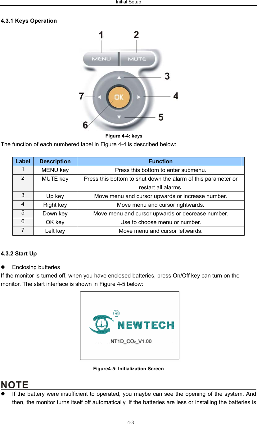
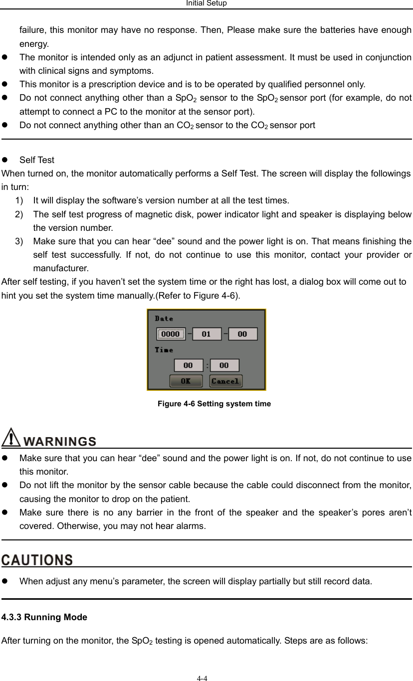
Newtech NT1D Handheld Vital Signs Monitor which transfers data to USB adaptor User Manual
Newtech,INC. Handheld Vital Signs Monitor which transfers data to USB adaptor
UserManual.wiki
>
Newtech
>
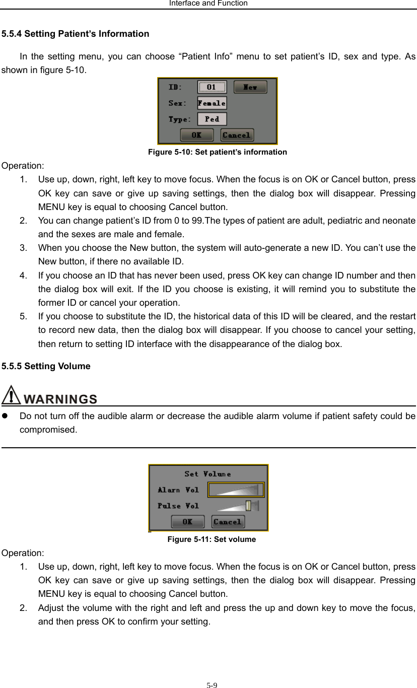
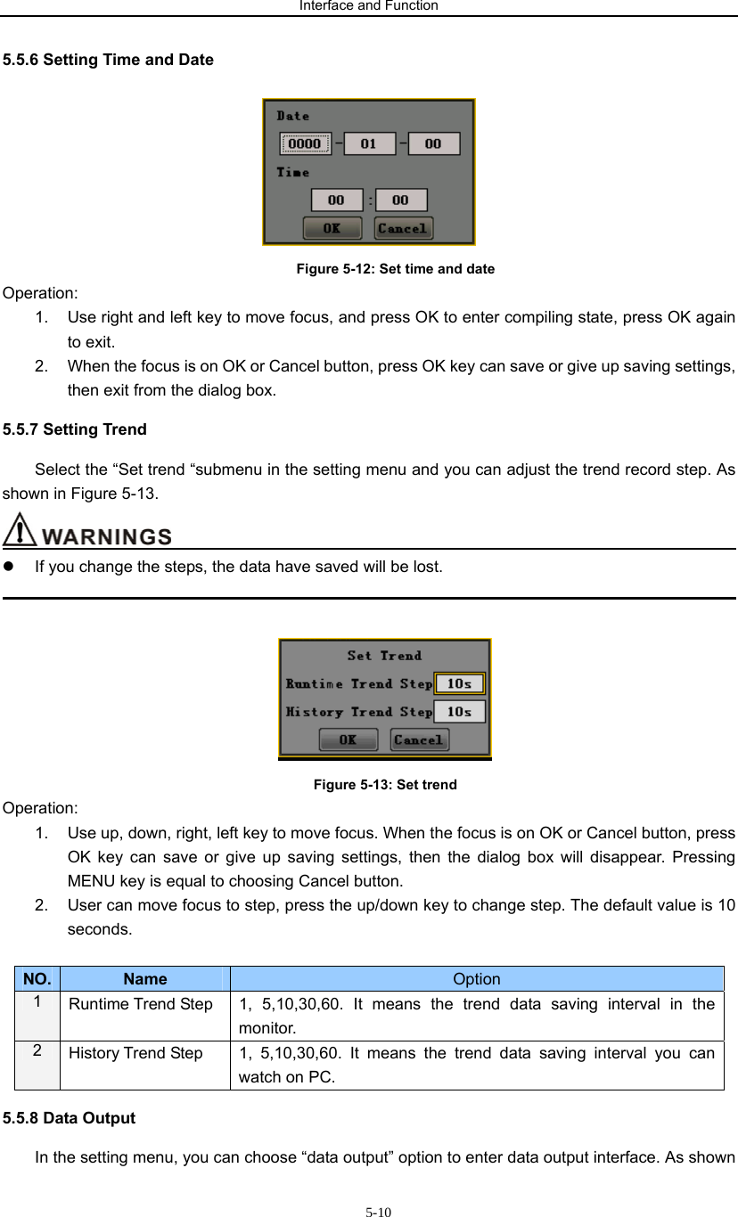
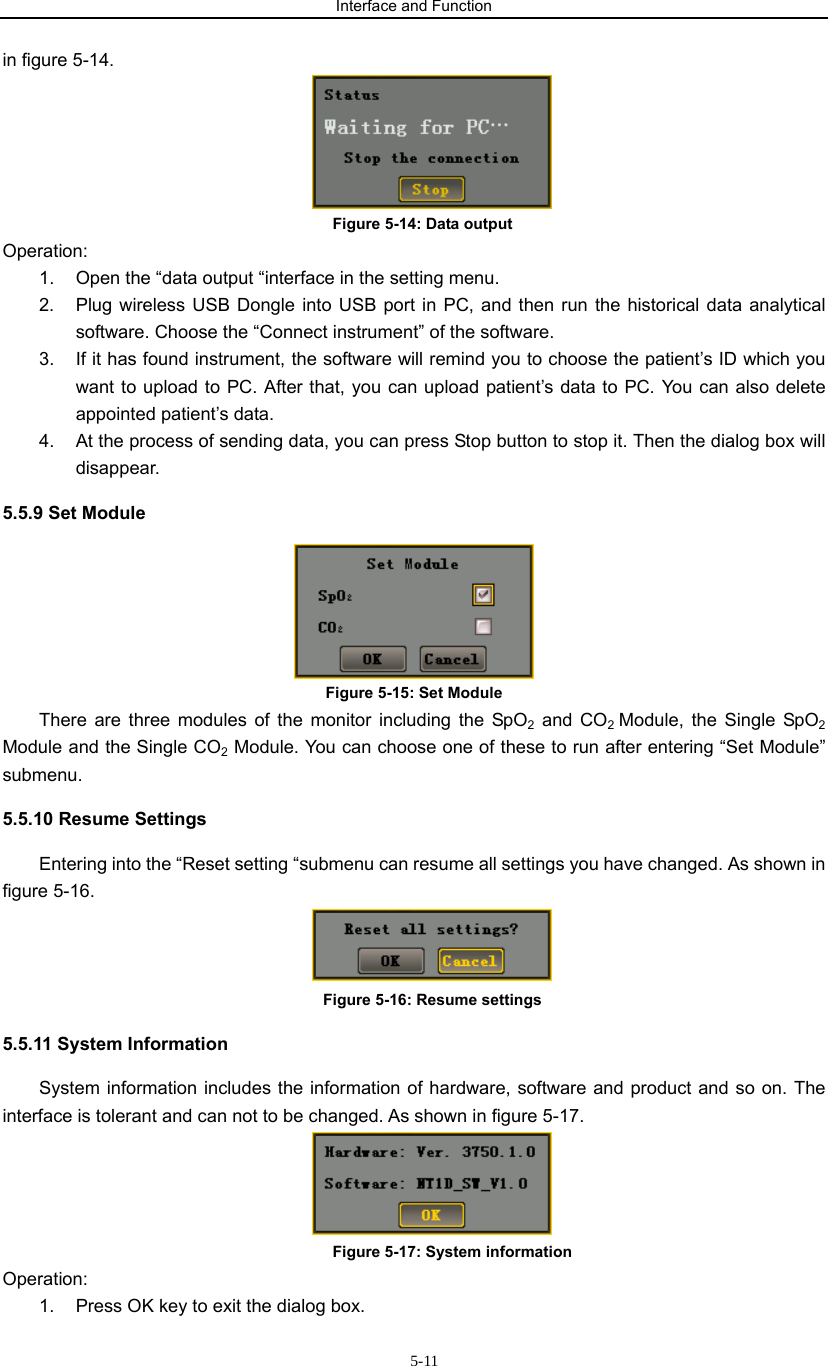
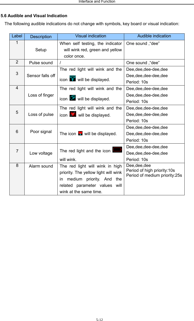
NT1D User Manual
User manual
Navigation menu
Upload a User Manual
Namespaces
Wiki Guide
HTML
PDF
Info
Views
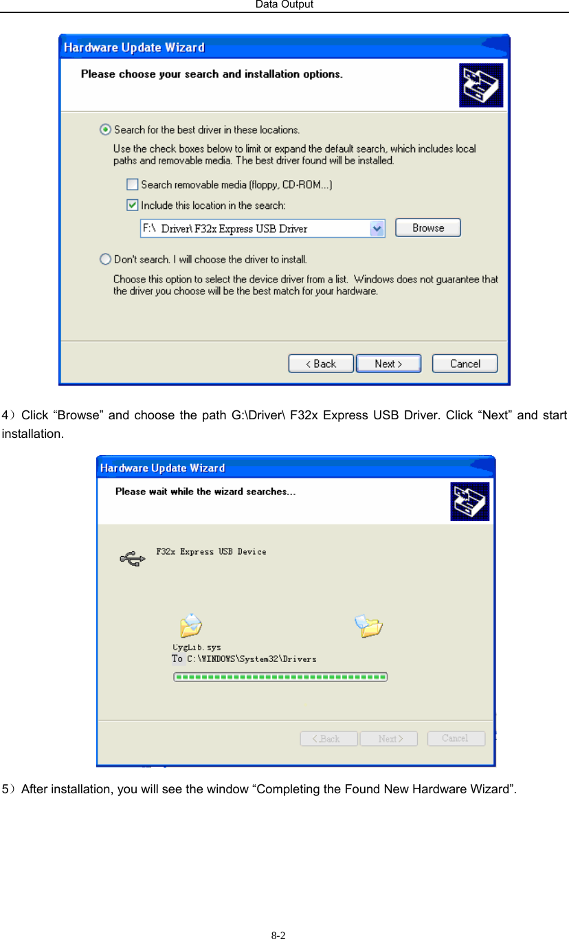
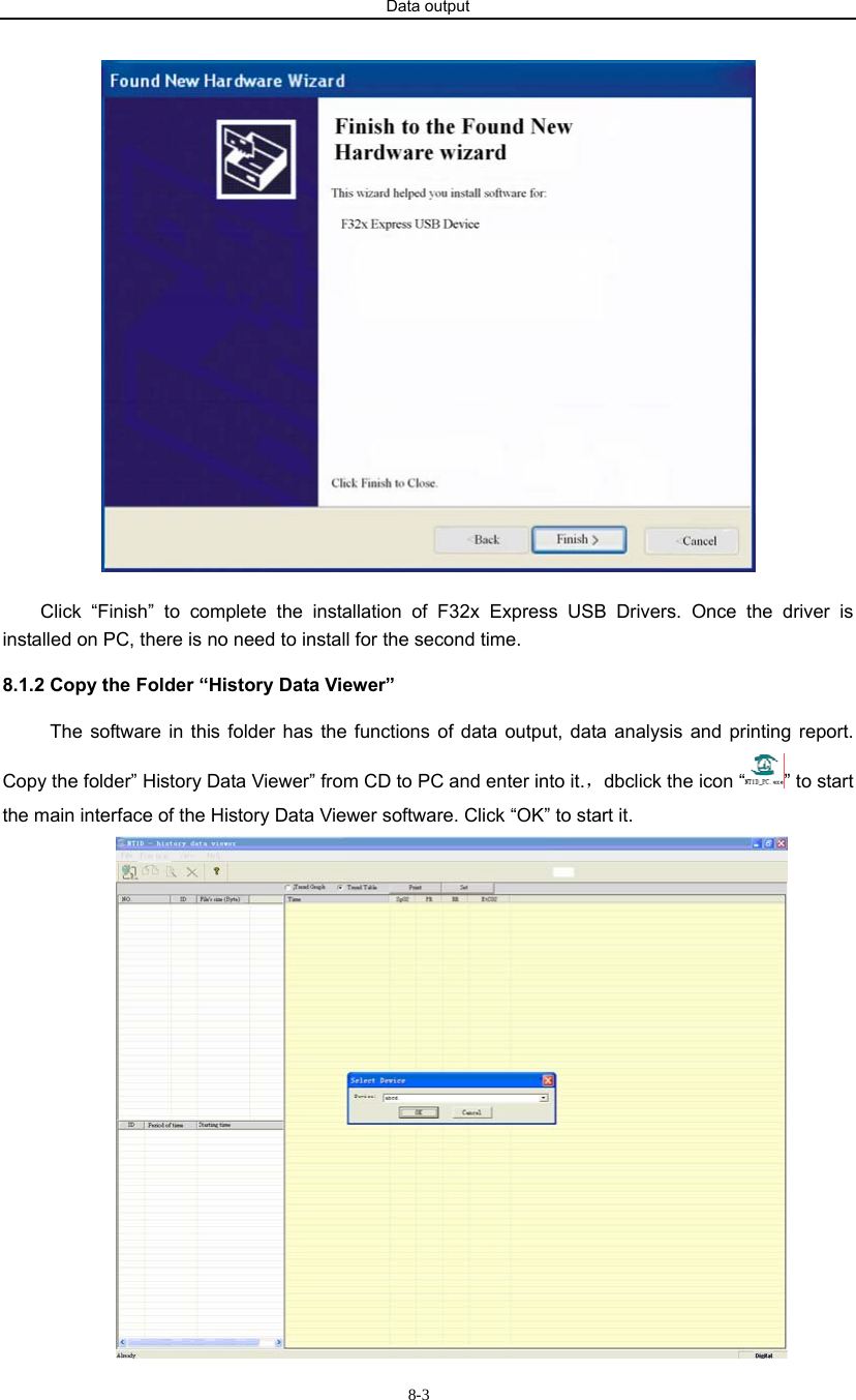
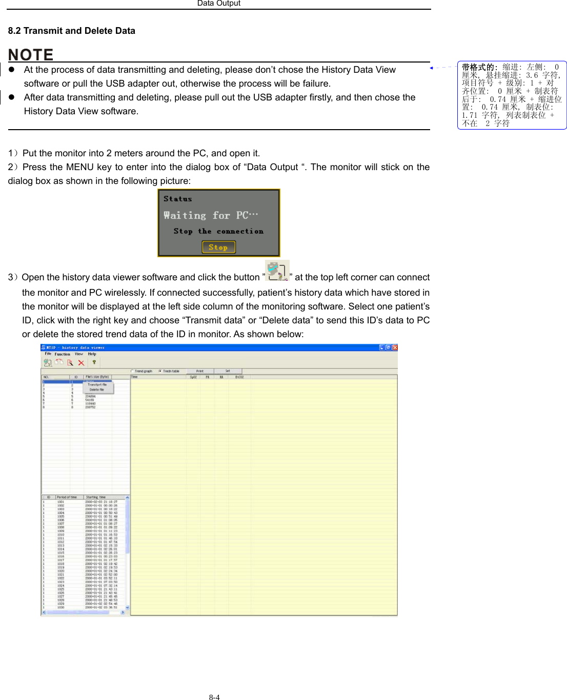
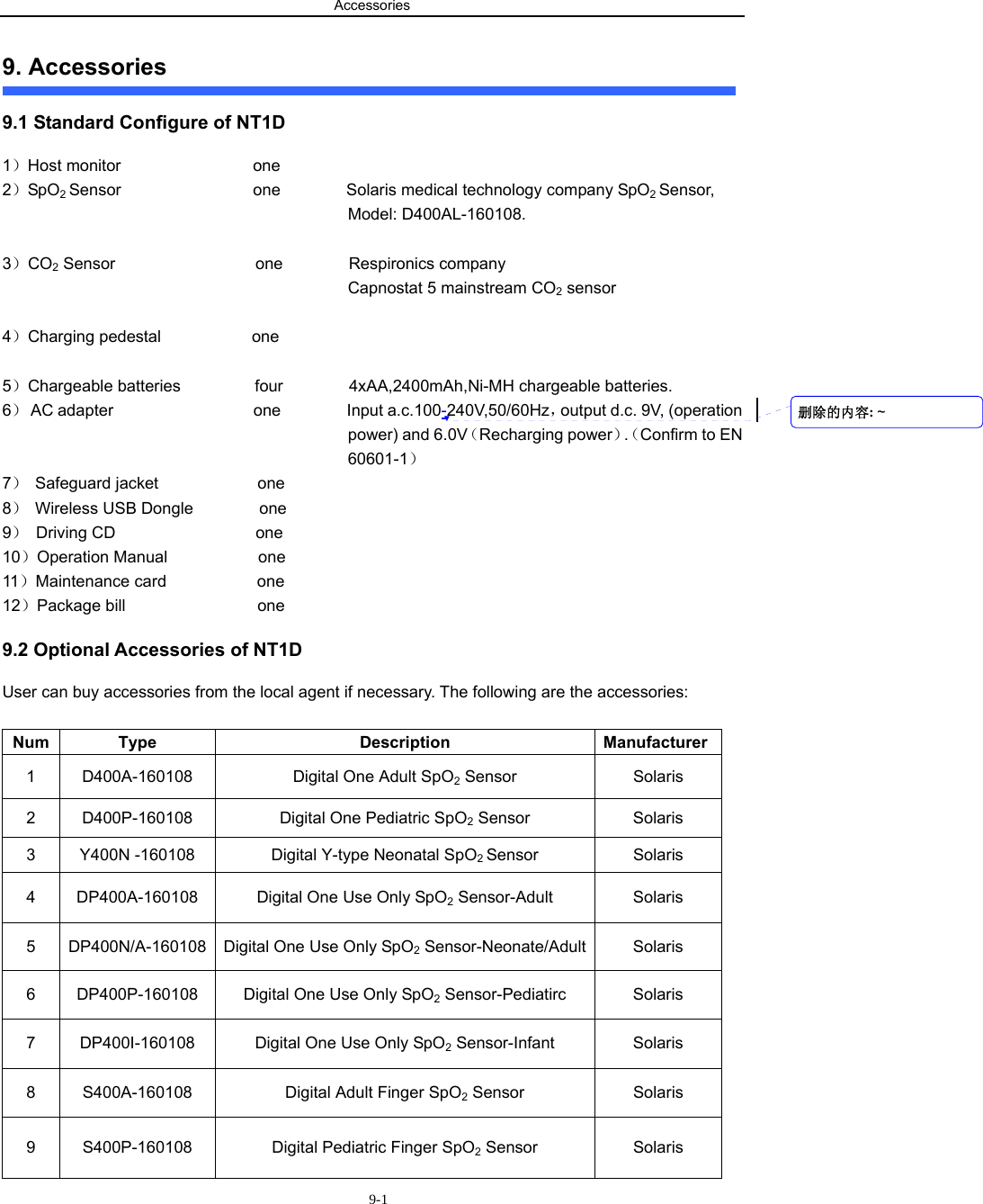
User Manual
Discussion / Help
Navigation