Netgear orporated FWG114PV2 ProSafe 802.11g Wireless Firewall/Print Server User Manual FullManual
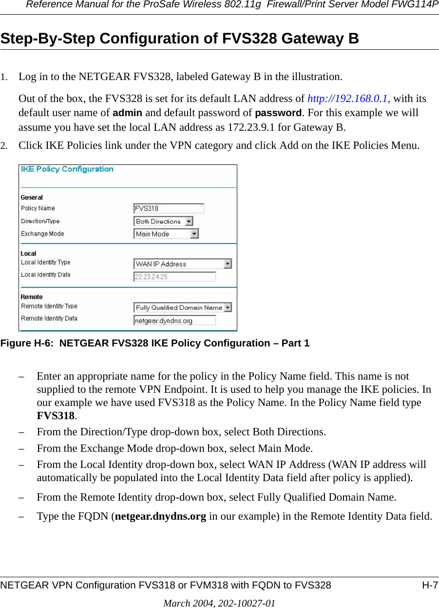
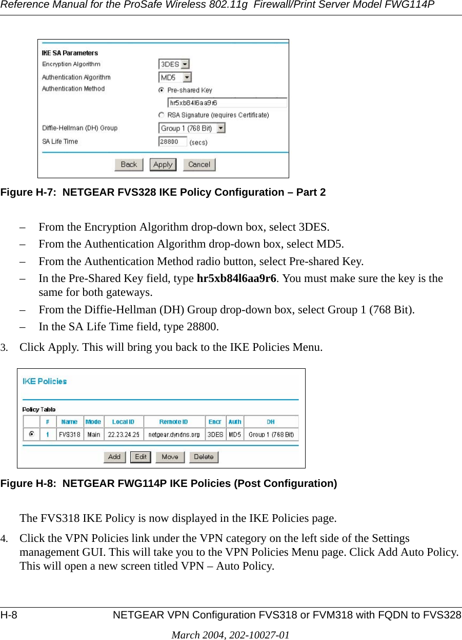
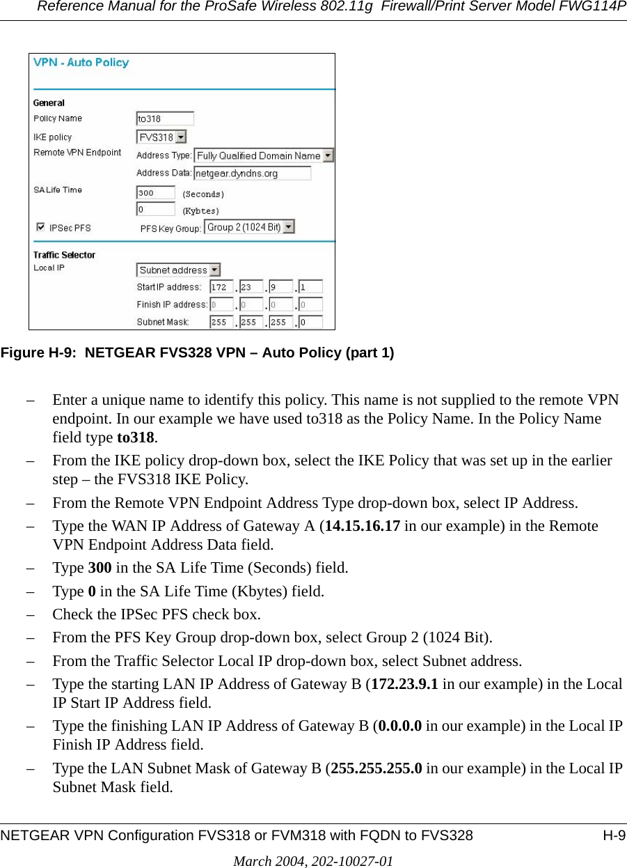
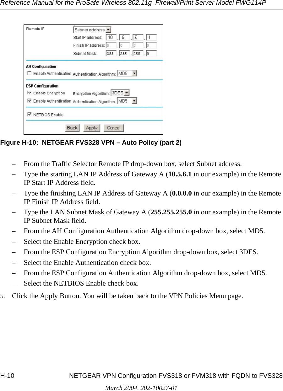
Netgear Incorporated ProSafe 802.11g Wireless Firewall/Print Server FullManual
Contents
- 1. Users Manual Part 1
- 2. Users Manual Part 2
- 3. Users Manual Part 3
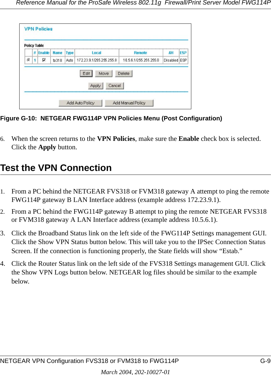
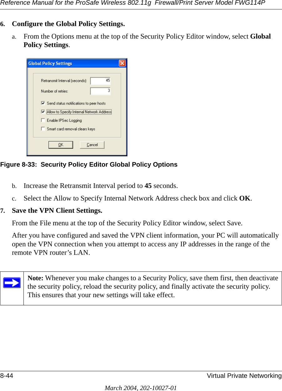
Users Manual Part 3
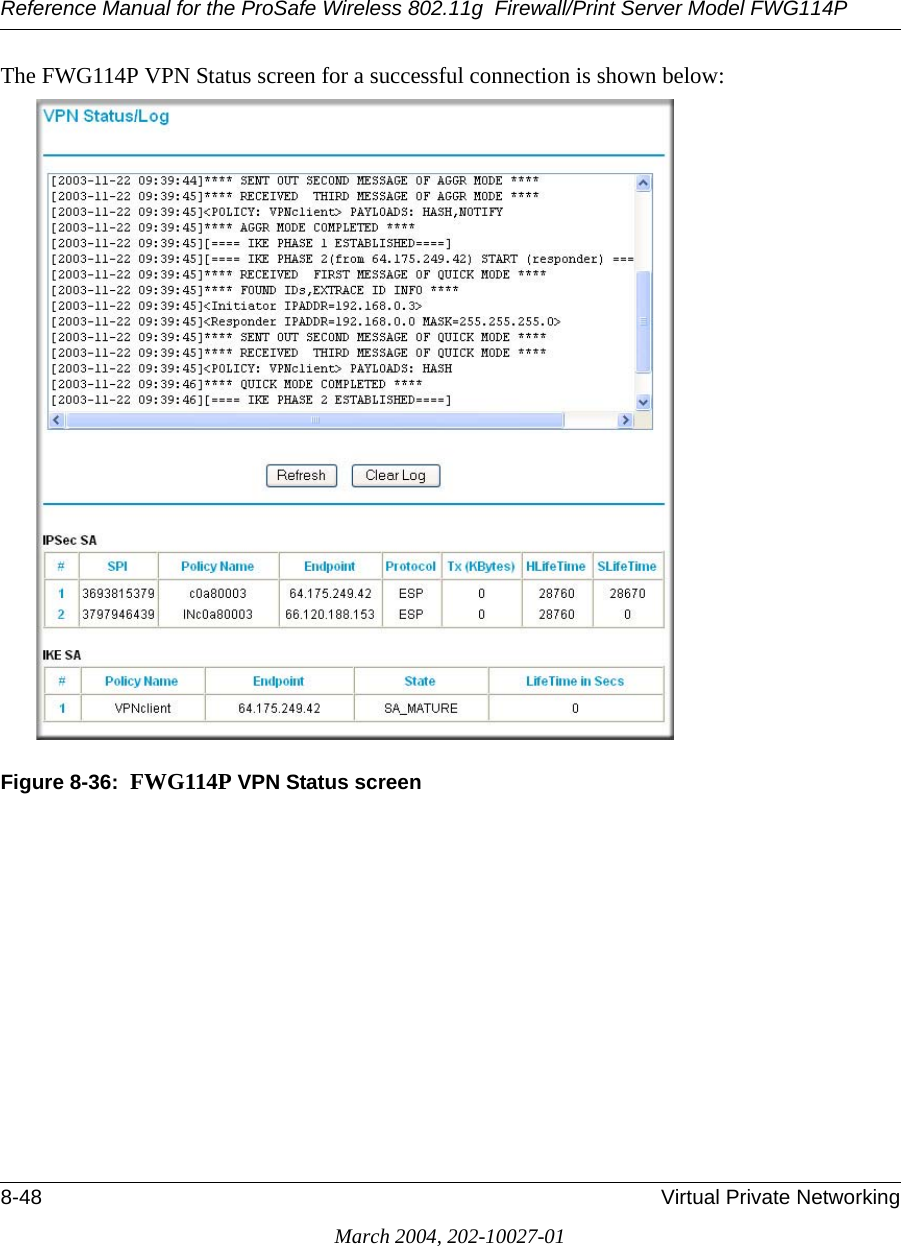
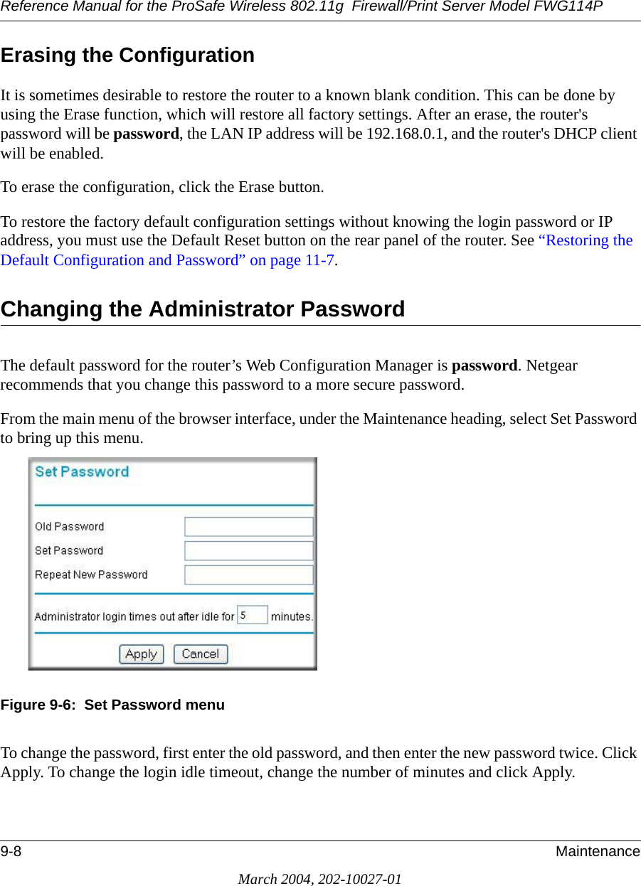
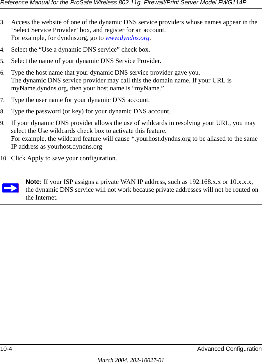
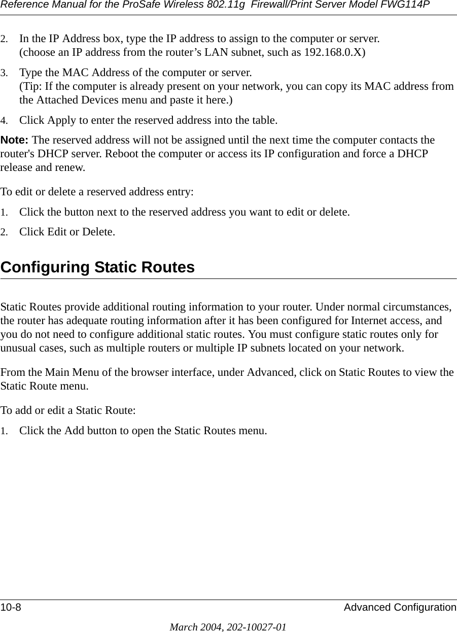
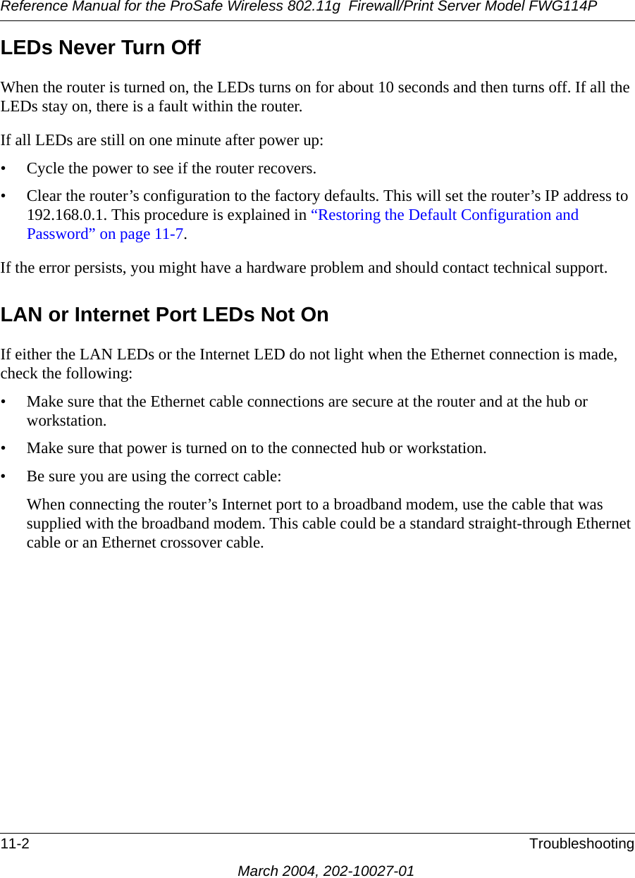
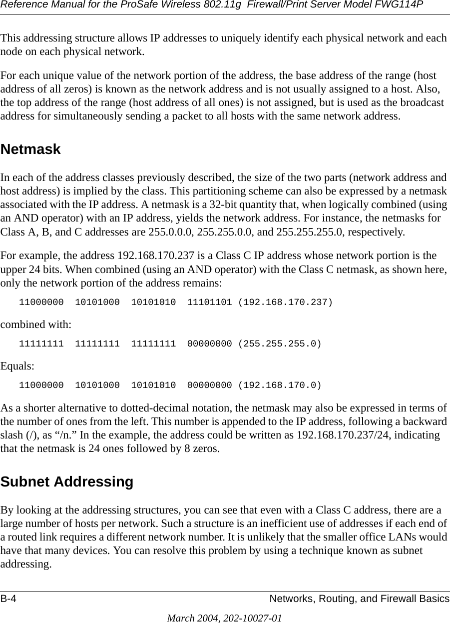
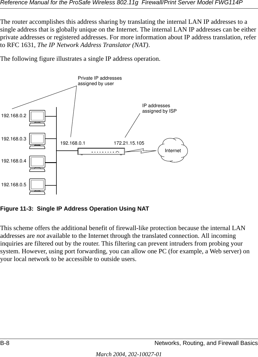
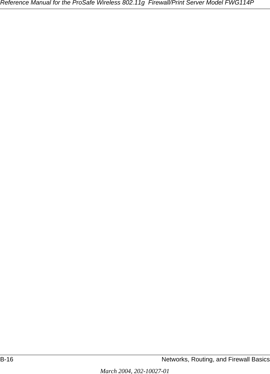
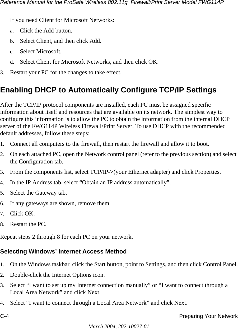
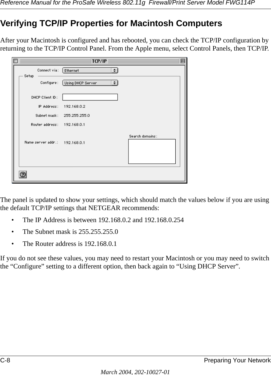
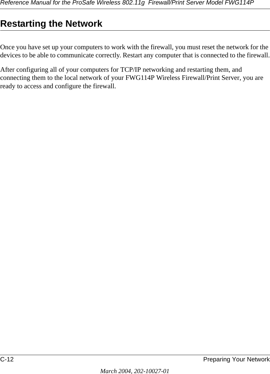
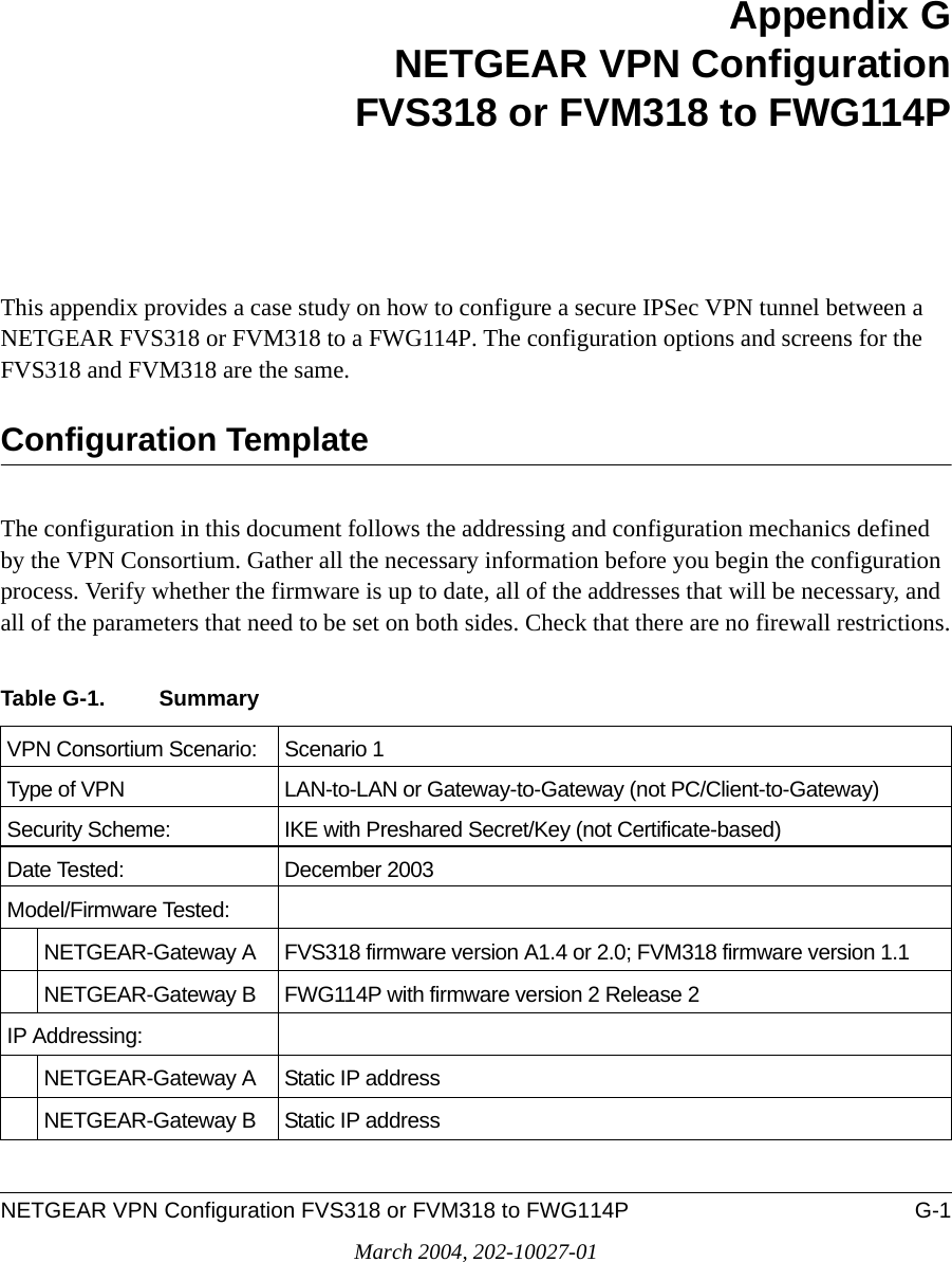
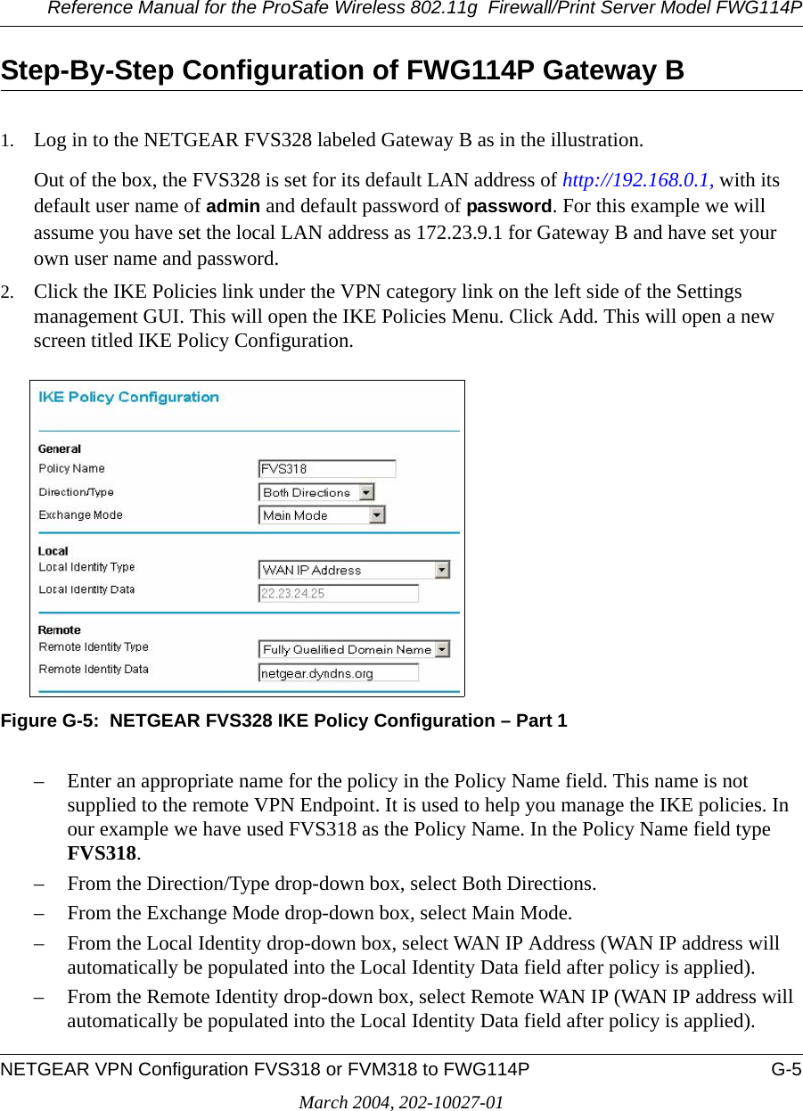
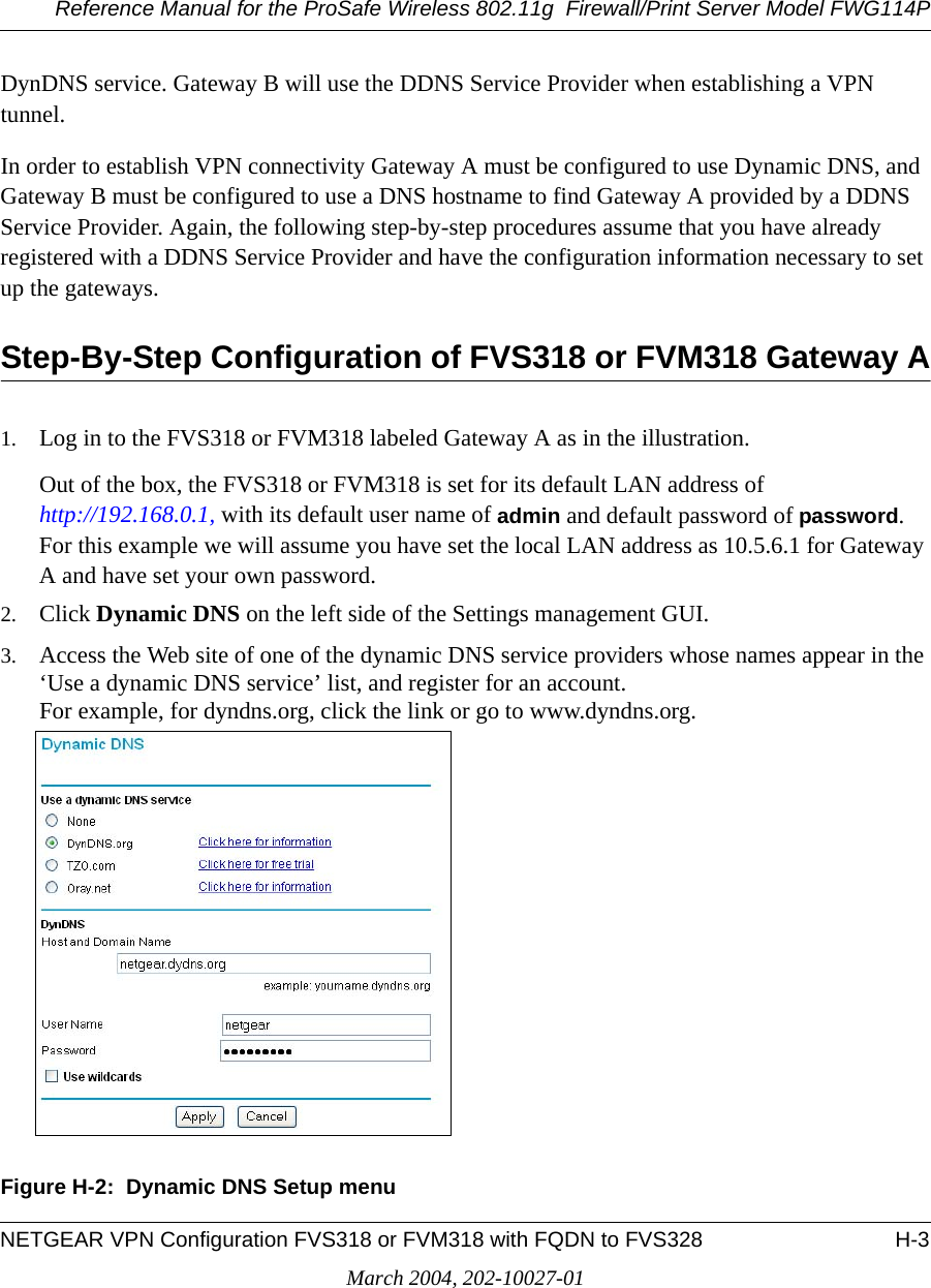
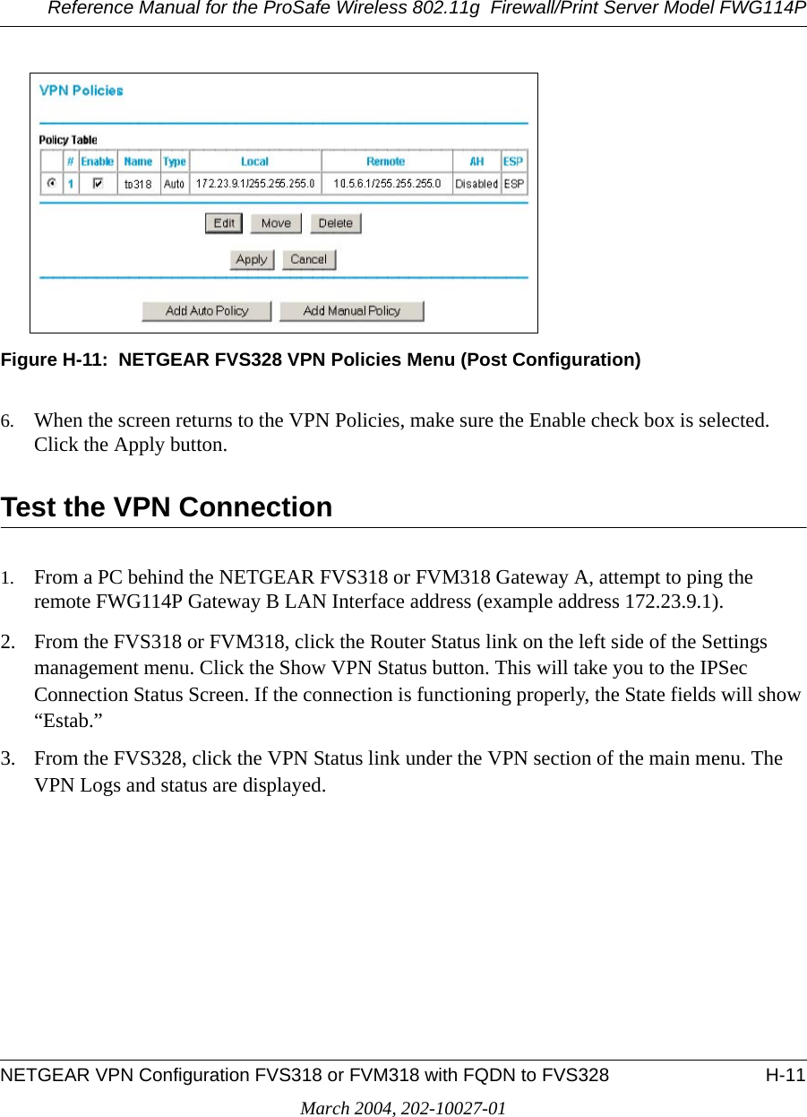
![Reference Manual for the ProSafe Wireless 802.11g Firewall/Print Server Model FWG114PD-2 Firewall Log FormatsMarch 2004, 202-10027-01The format is:<DATE> <TIME> <PKT_TYPE> <SRC_IP> <SRC_INF> <DST_IP > <DST_INF> <ACTION><DESCRIPTION>[Fri, 2003-12-05 22:19:42] - UDP Packet - Source:172.31.12.233,138 ,WAN - Destination:172.31.12.255,138 ,LAN [Drop] - [Inbound Default rule match][Fri, 2003-12-05 22:35:04] - TCP Packet - Source:172.31.12.156,34239 ,WAN - Destination:192.168.0.10,21[FTP Control] ,LAN [Forward] - [Inbound Rule(1) match][Fri, 2003-12-05 22:35:11] - UDP Packet - Source:172.31.12.200,138 ,WAN - Destination:172.31.12.255,138 ,LAN [Forward] - [Inbound Rule(1) not match]Notes:SRC_INF = WANDST_INF = LANDESCRIPTION = "Inbound rule match", "Inbound Default rule match"PKT_TYPE = "UDP packet", "TCP connection", "ICMP packet"Inbound LogIncoming packets that match the Firewall rules are logged.The format is:<DATE> <TIME> <PKT_TYPE> <SRC_IP> <SRC_INF> <DST_IP > <DST_INF> <ACTION><DESCRIPTION>[Fri, 2003-12-05 22:59:56] - ICMP Packet [Echo Request] - Source:192.168.0.10,LAN - Destination:192.168.0.1,WAN [Forward] - [Outbound Default rule match][Fri, 2003-12-05 23:00:58] - ICMP Packet [Echo Request] - Source:192.168.0.10,LAN - Destination:172.31.12.200,WAN [Forward] - [Outbound Default rule match][Fri, 2003-12-05 23:02:30] - TCP Packet - Source:192.168.0.10,3472 ,LAN - Destination:216.239.39.99,80[HTTP] ,WAN [Forward] - [Outbound Default rule match]Notes:SRC_INF = LANDST_INF = WANDESCRIPTION = "Outbound rule match", "Outbound Default rule match"PKT_TYPE = "UDP packet", "TCP connection", "ICMP packet"Other IP TrafficSome special packets matching the Firewall rules, like VPN connection, etc. are logged.](https://usermanual.wiki/Netgear-orporated/FWG114PV2.Users-Manual-Part-3/User-Guide-477792-Page-70.png)
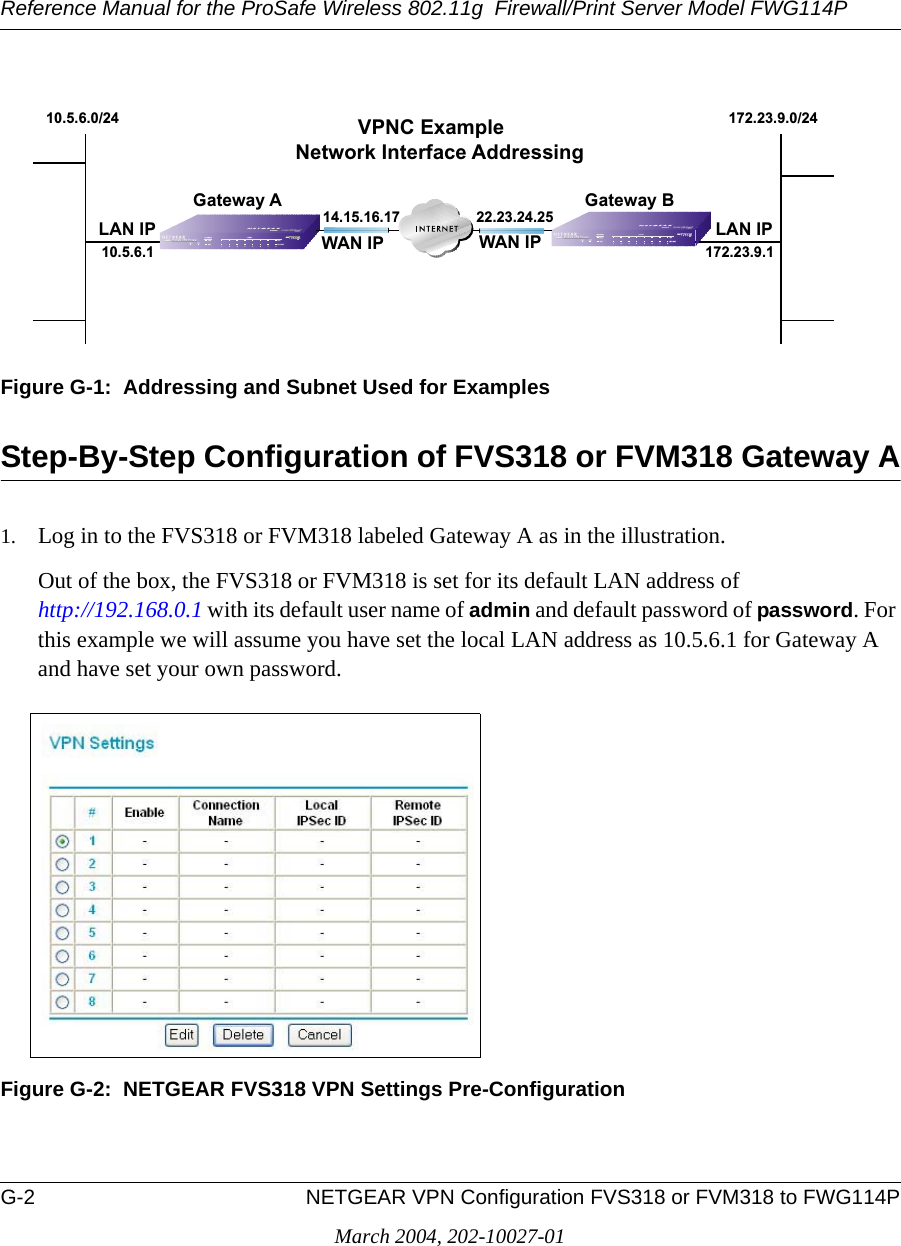
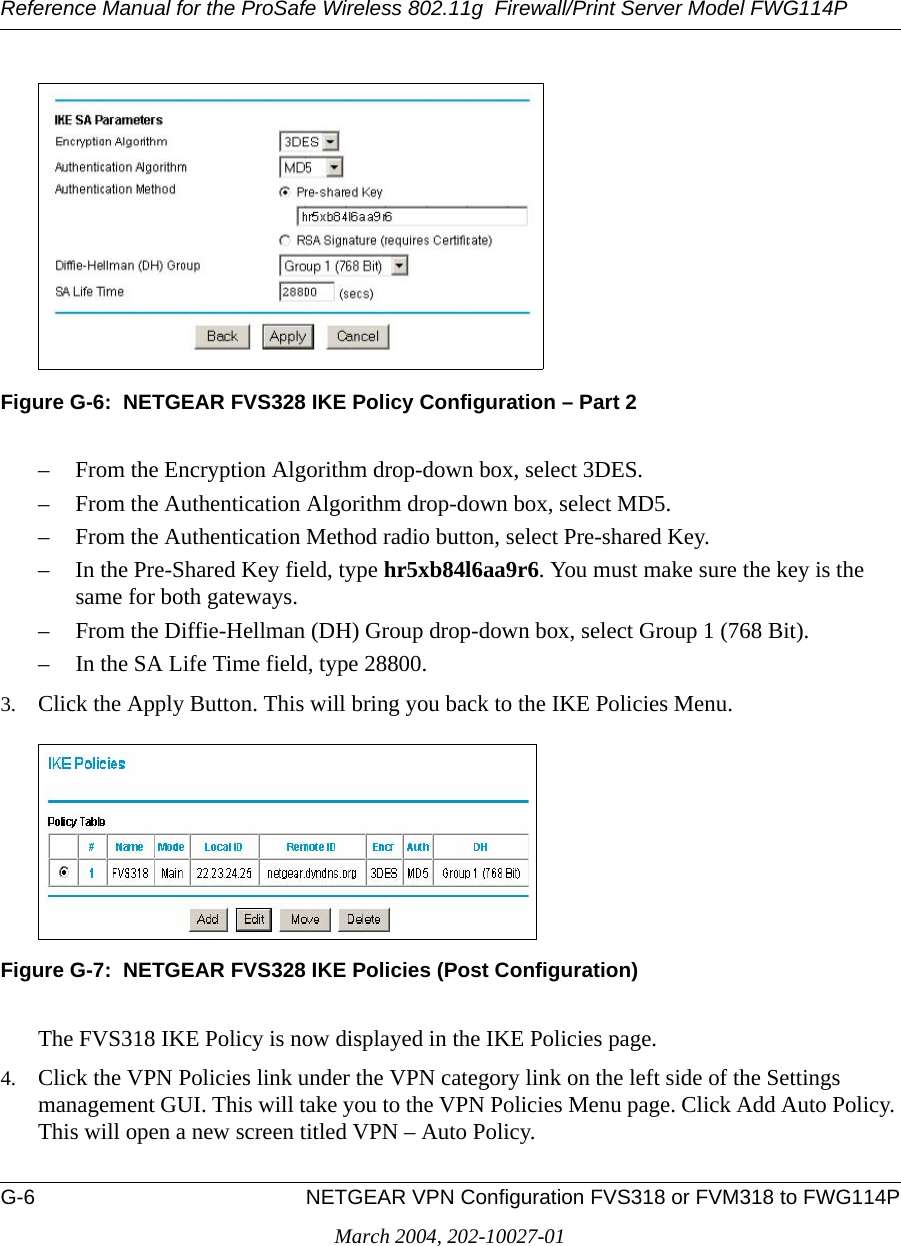
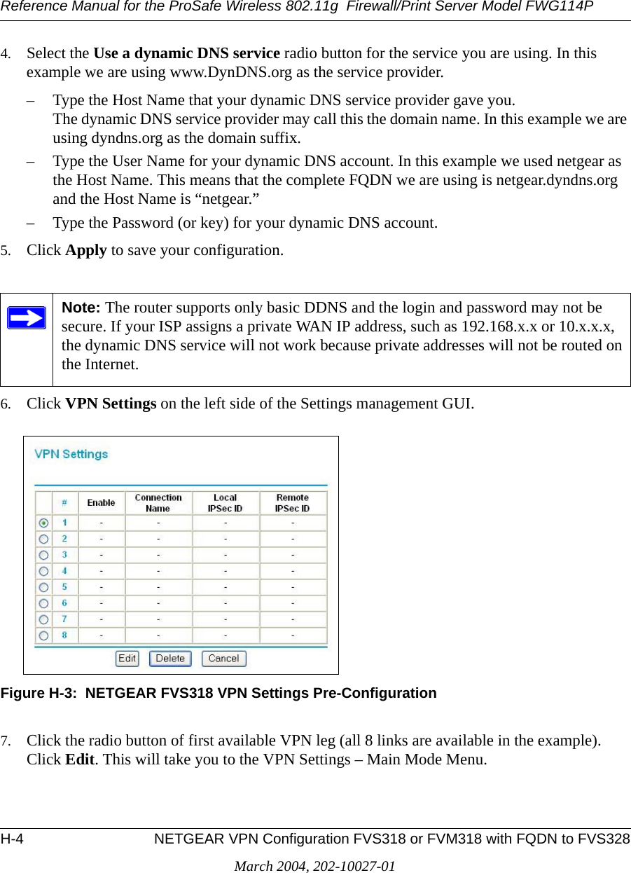
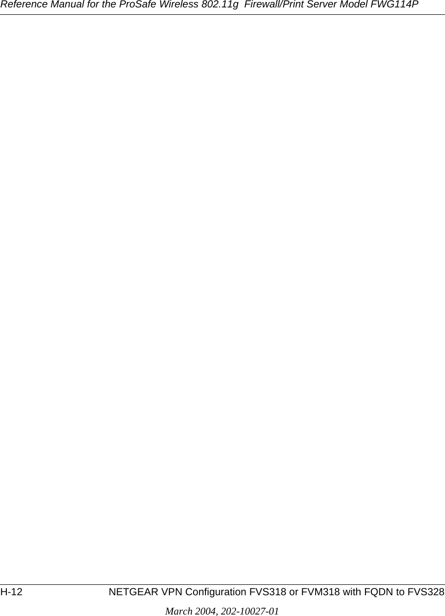
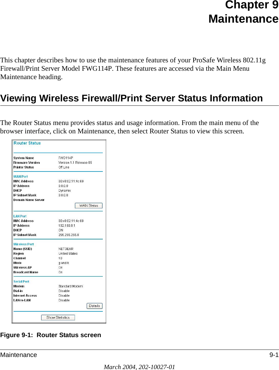
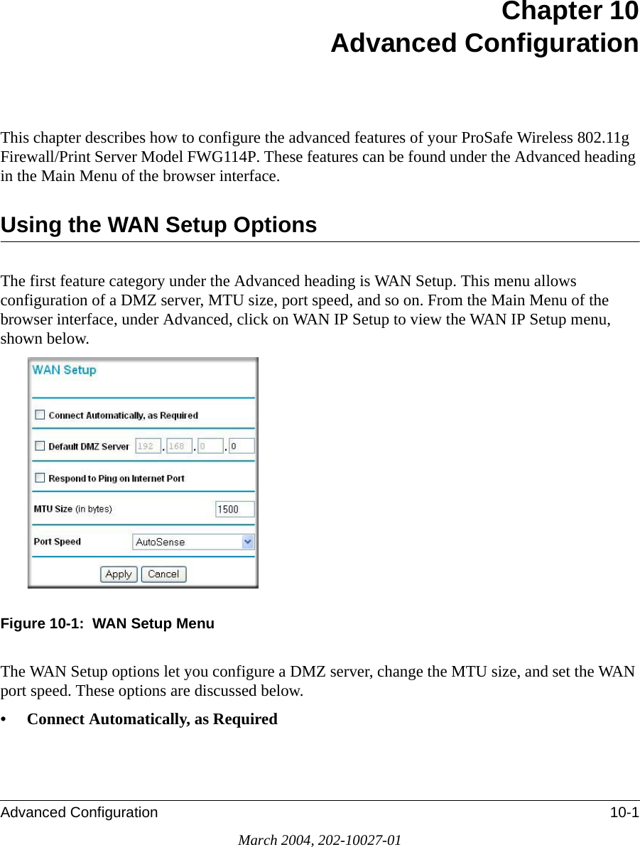
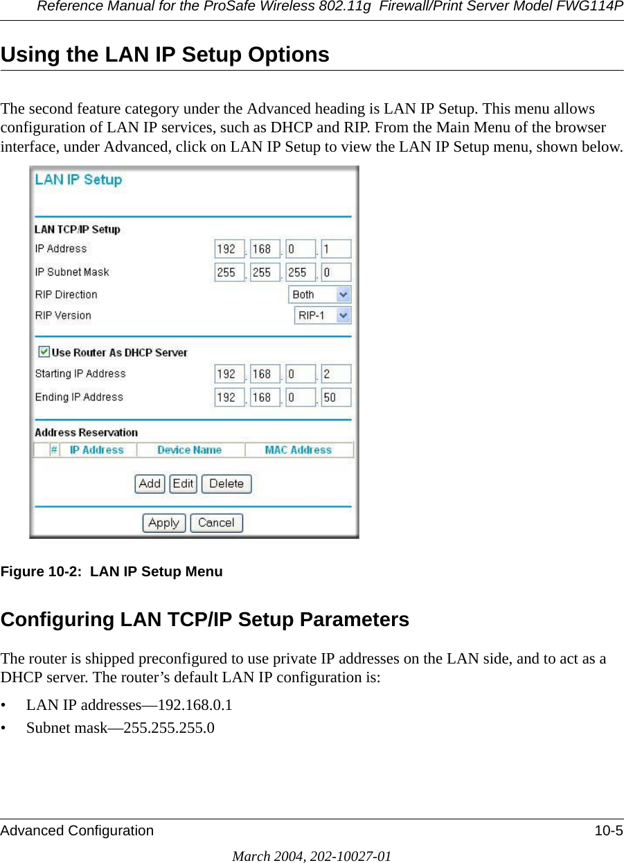
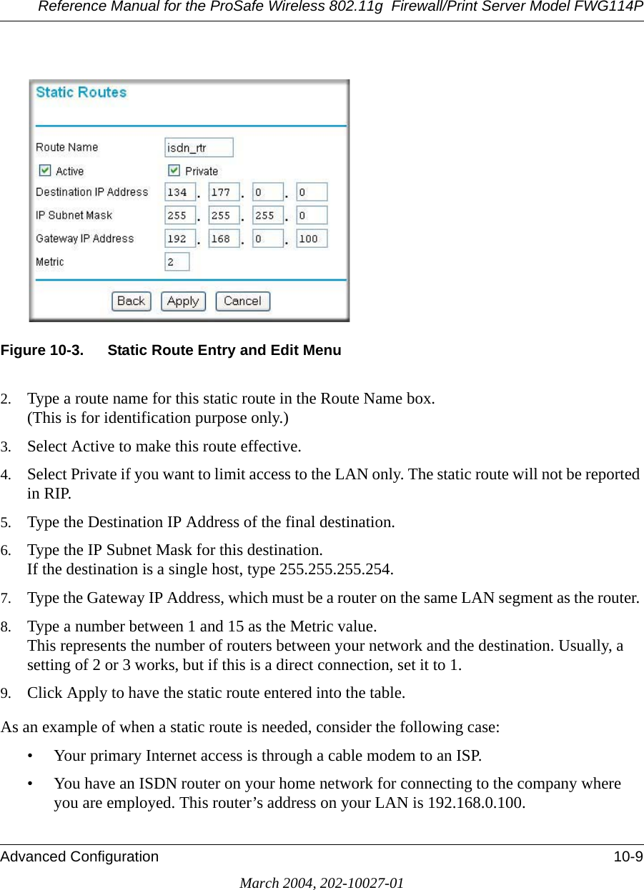
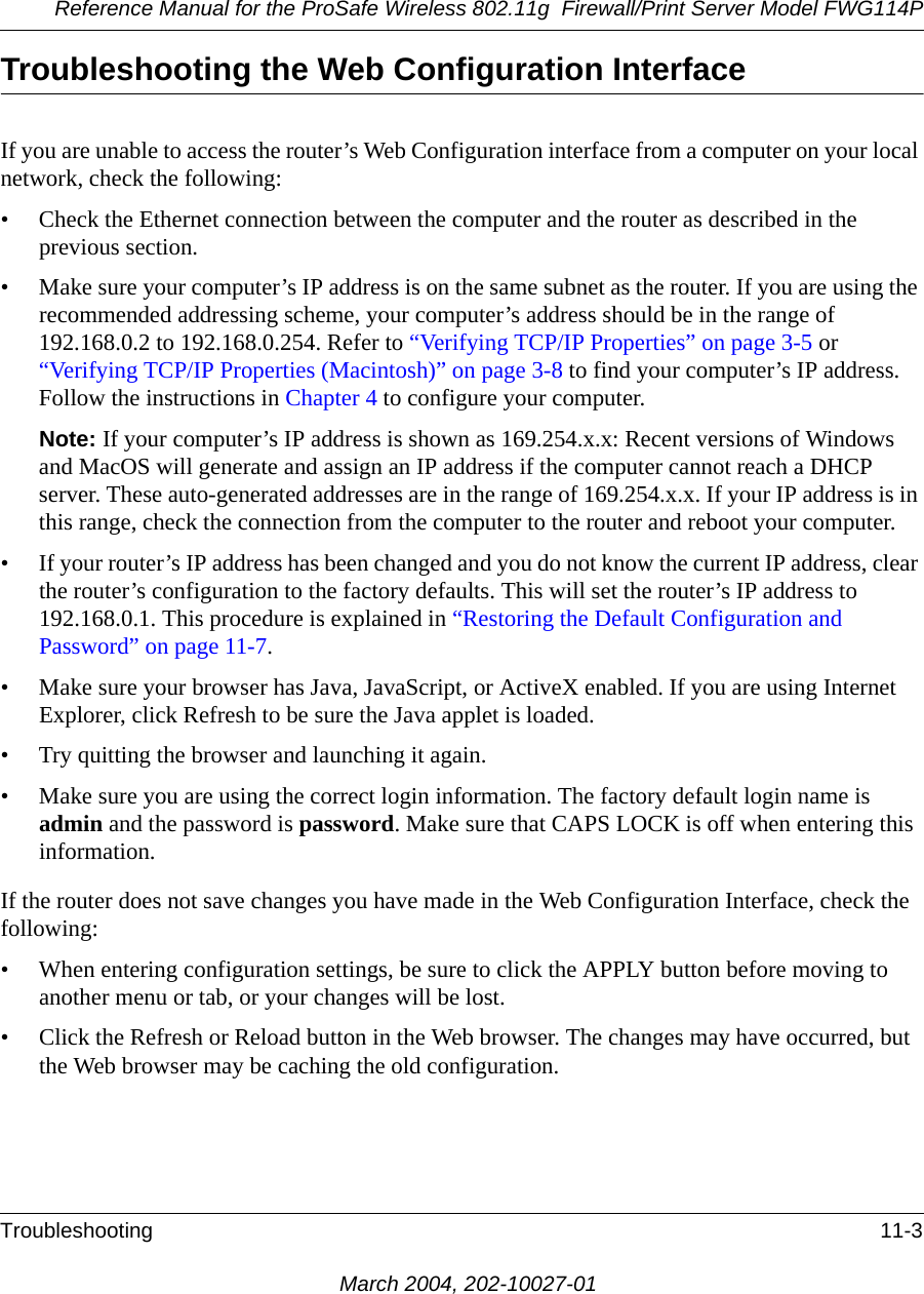
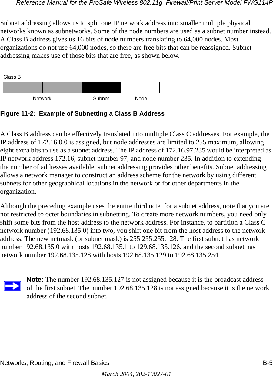
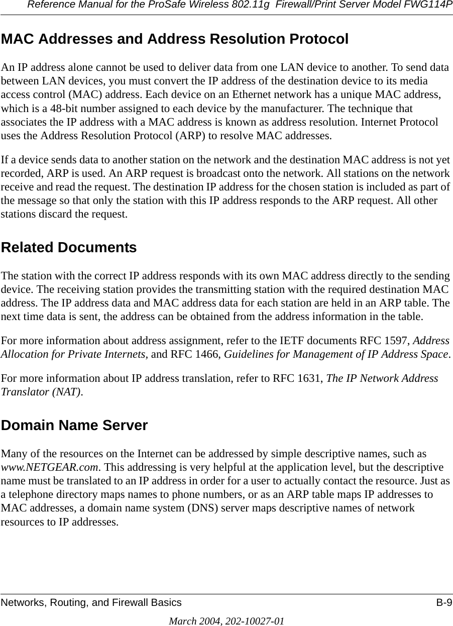
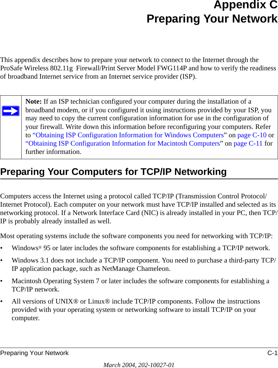
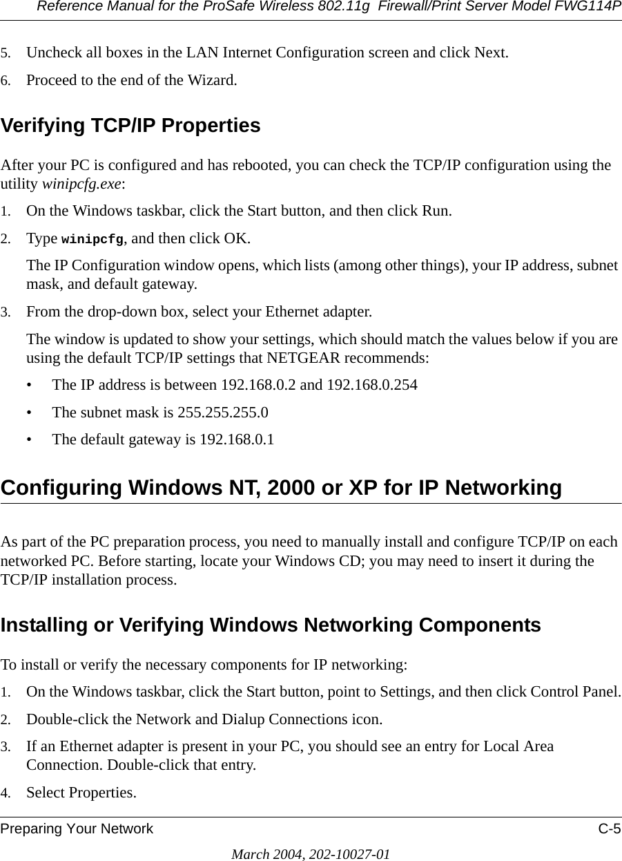
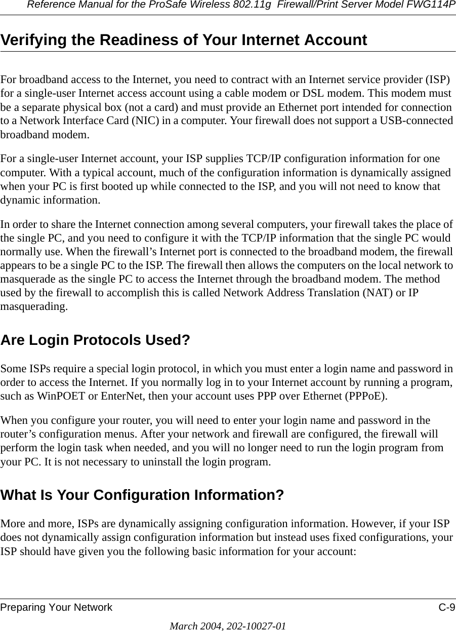
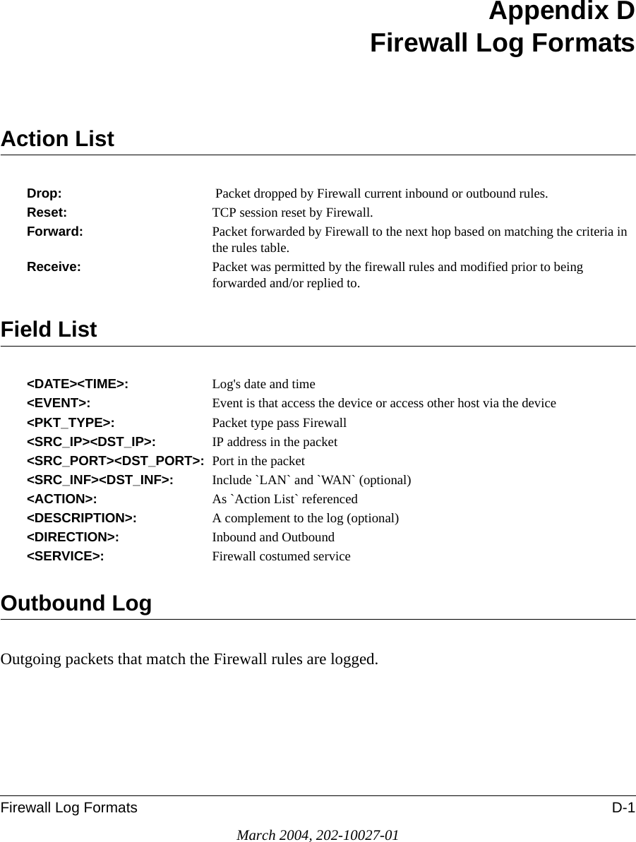
![Reference Manual for the ProSafe Wireless 802.11g Firewall/Print Server Model FWG114PFirewall Log Formats D-3March 2004, 202-10027-01The format is:<DATE><TIME><PKT_TYPE>< SRC_IP><SRC_PORT ><SRC_INF>< DST_IP><DST_PORT ><DST_PORT><ACTION><DESCRIPTION><DATE><TIME> <PKT_TYPE> <SRC_IP> <SRC_INF> <DST_IP> <DST_INF> <ACTION> <DESCRIPTION>[Wed, 2003-07-30 17:43:28] - IPSEC Packet - Source: 64.3.3.201, 37180 WAN - Destination: 10.10.10.4,80[HTTP] LAN - [Drop] [VPN Packet][Wed, 2003-07-30 18:44:50] - IP Packet [Type Field: 321] - Source 18.7.21.69 192.168.0.3 - [Drop]Notes:DESCRIPTION = "VPN Packet"PKT_TYPE = "GRE", "AH", "ESP", "IP packet [Type Field: Num]", "IPSEC"ACTION = "Forward", "Drop"Router OperationOperations that the router initiates are logged.The format is:<DATE><TIME><EVENT>[Wed, 2003-07-30 16:30:59] - Log emailed[Wed, 2003-07-30 13:38:31] - NETGEAR activated[Wed, 2003-07-30 13:42:01] - NTP Reply InvalidThe format is:<DATE><TIME><EVENT><DST_IP><DATE><TIME><EVENT><SRC_IP>[Wed, 2003-07-30 16:32:33] - Send out NTP Request to 207.46.130.100[Wed, 2003-07-30 16:35:27] - Receive NTP Reply from 207.46.130.100](https://usermanual.wiki/Netgear-orporated/FWG114PV2.Users-Manual-Part-3/User-Guide-477792-Page-71.png)
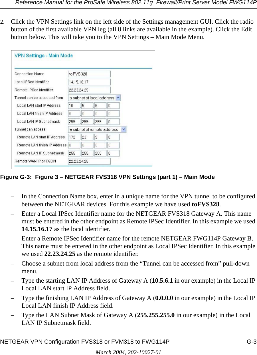
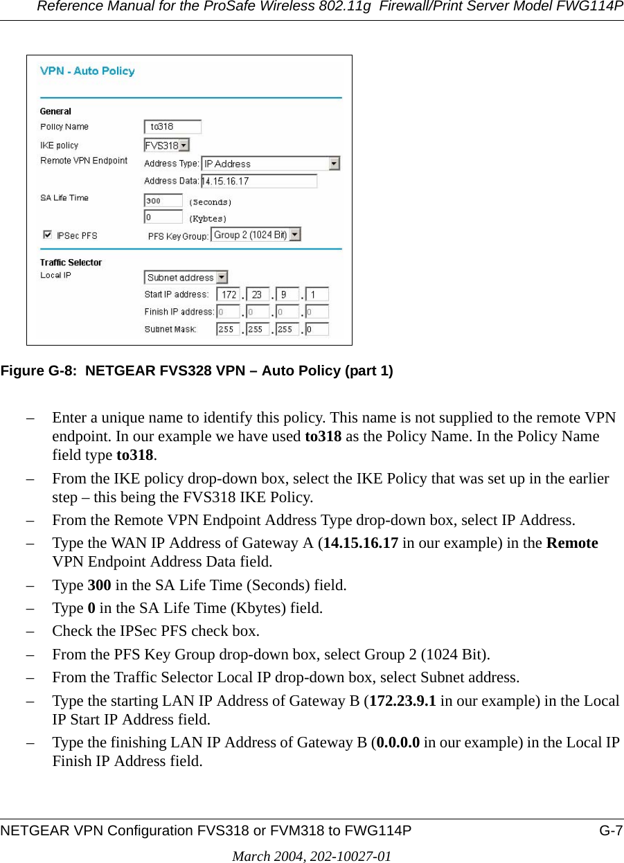
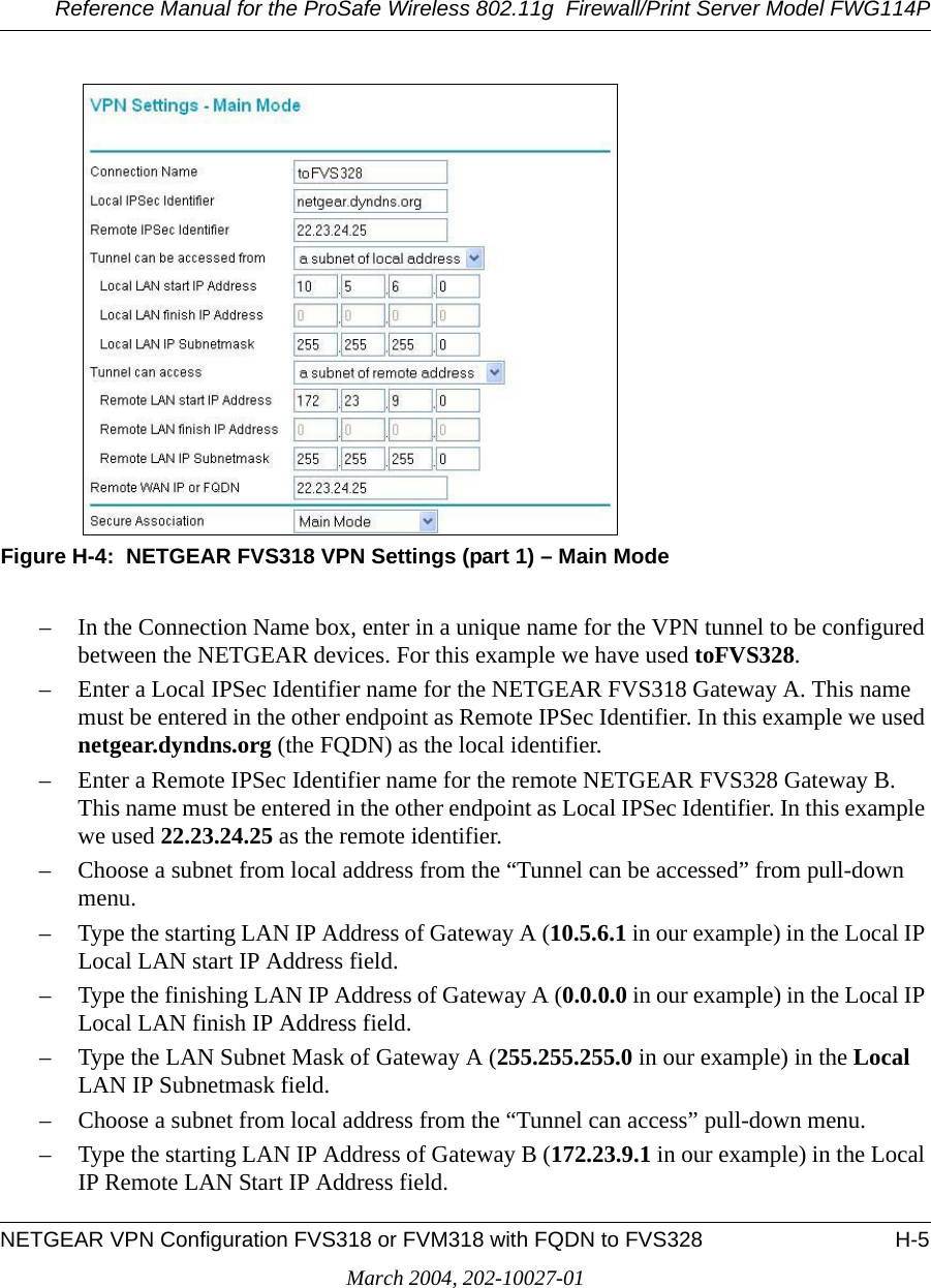
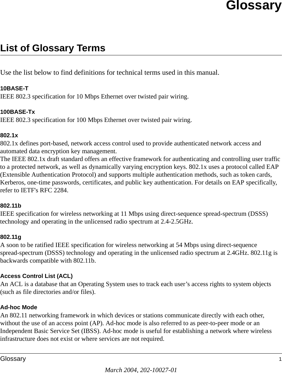
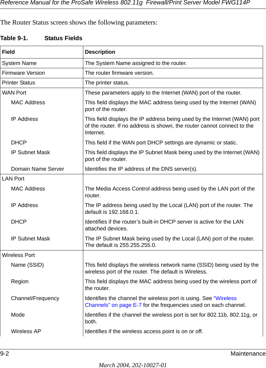
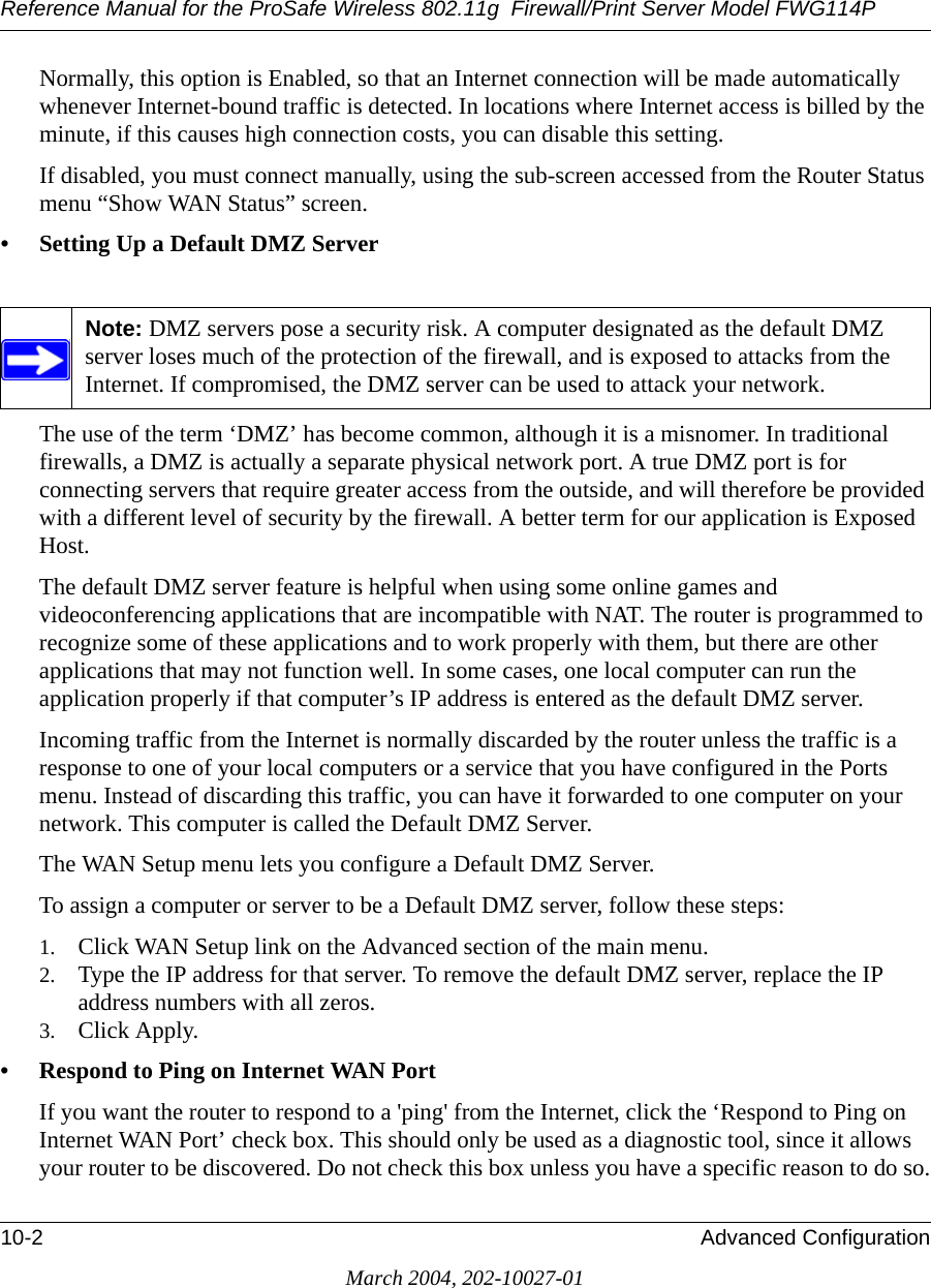
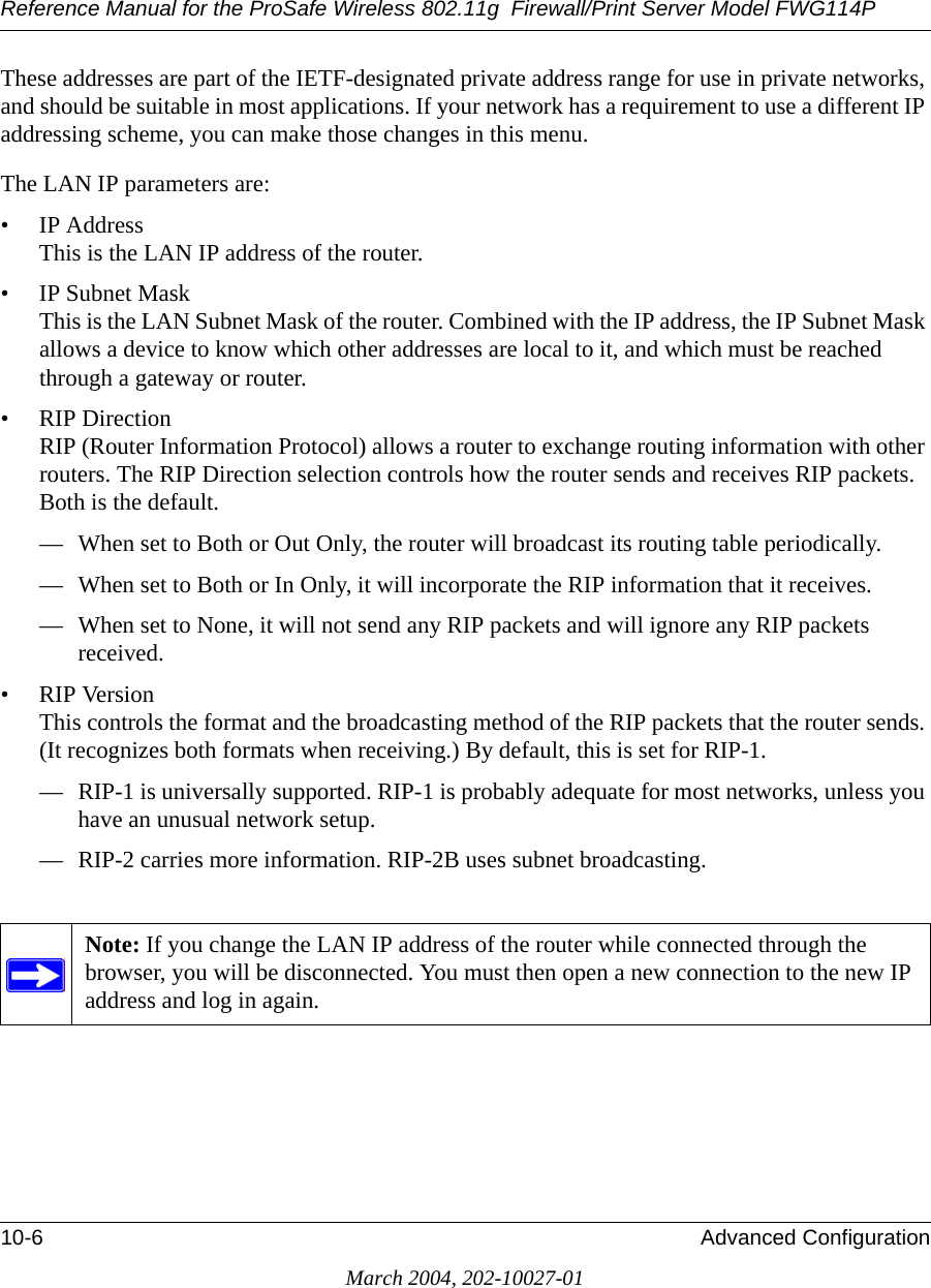
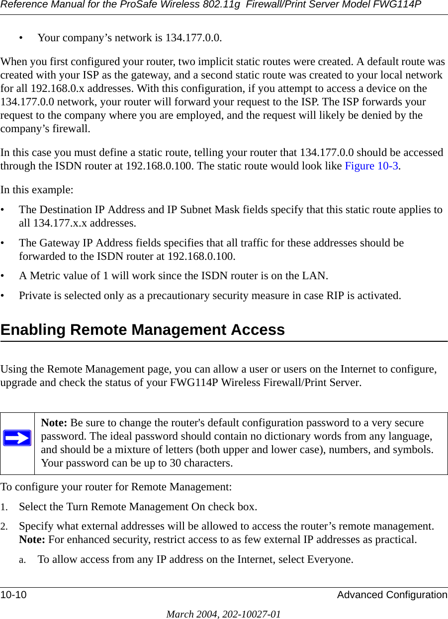
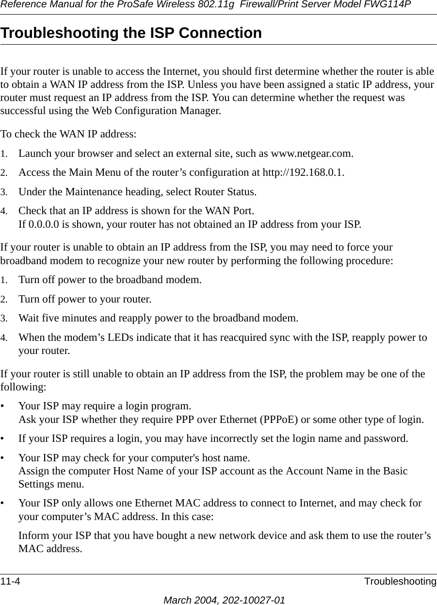
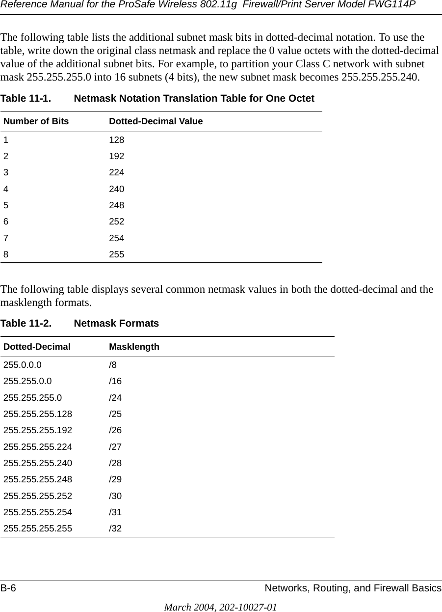
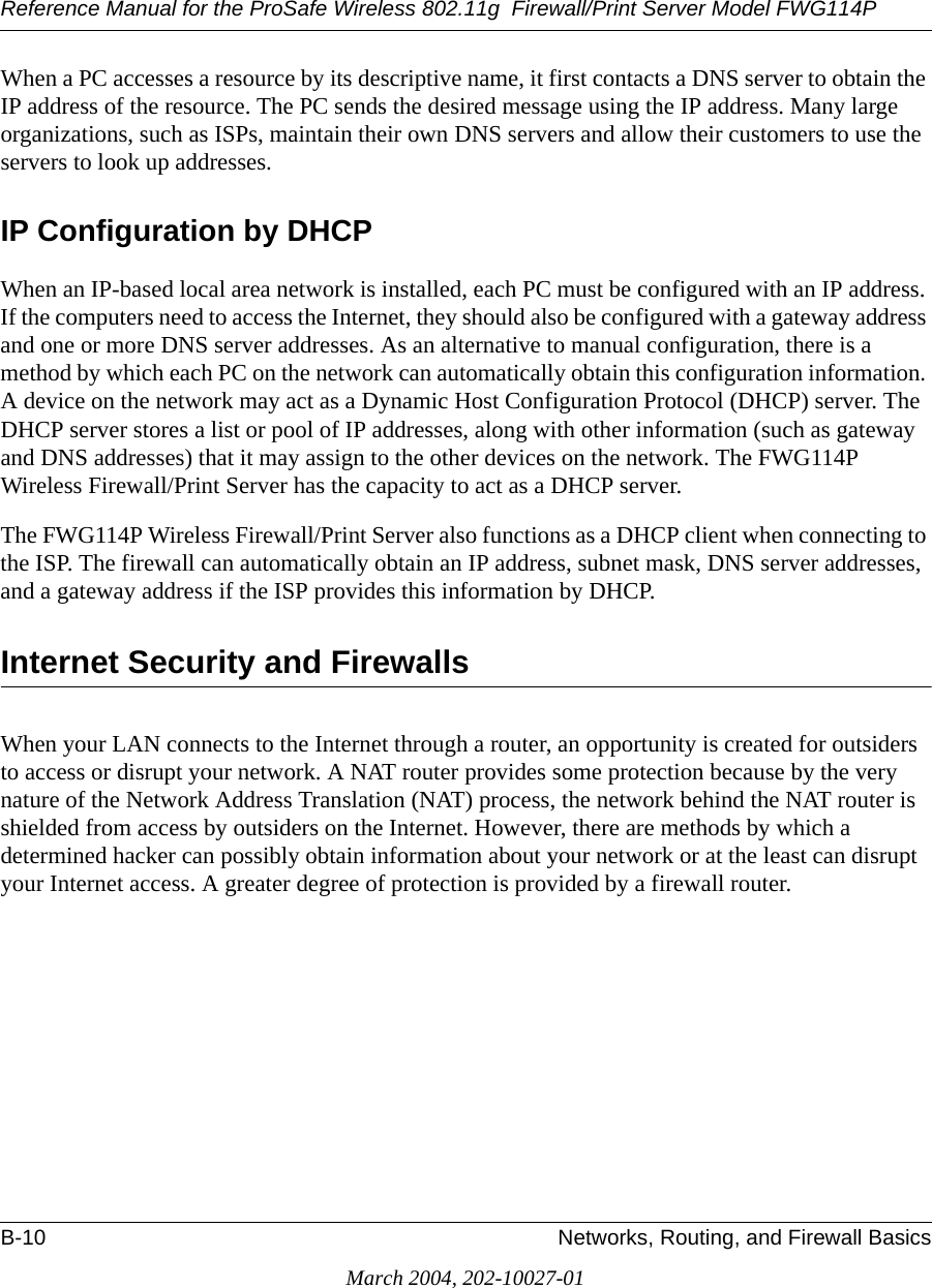
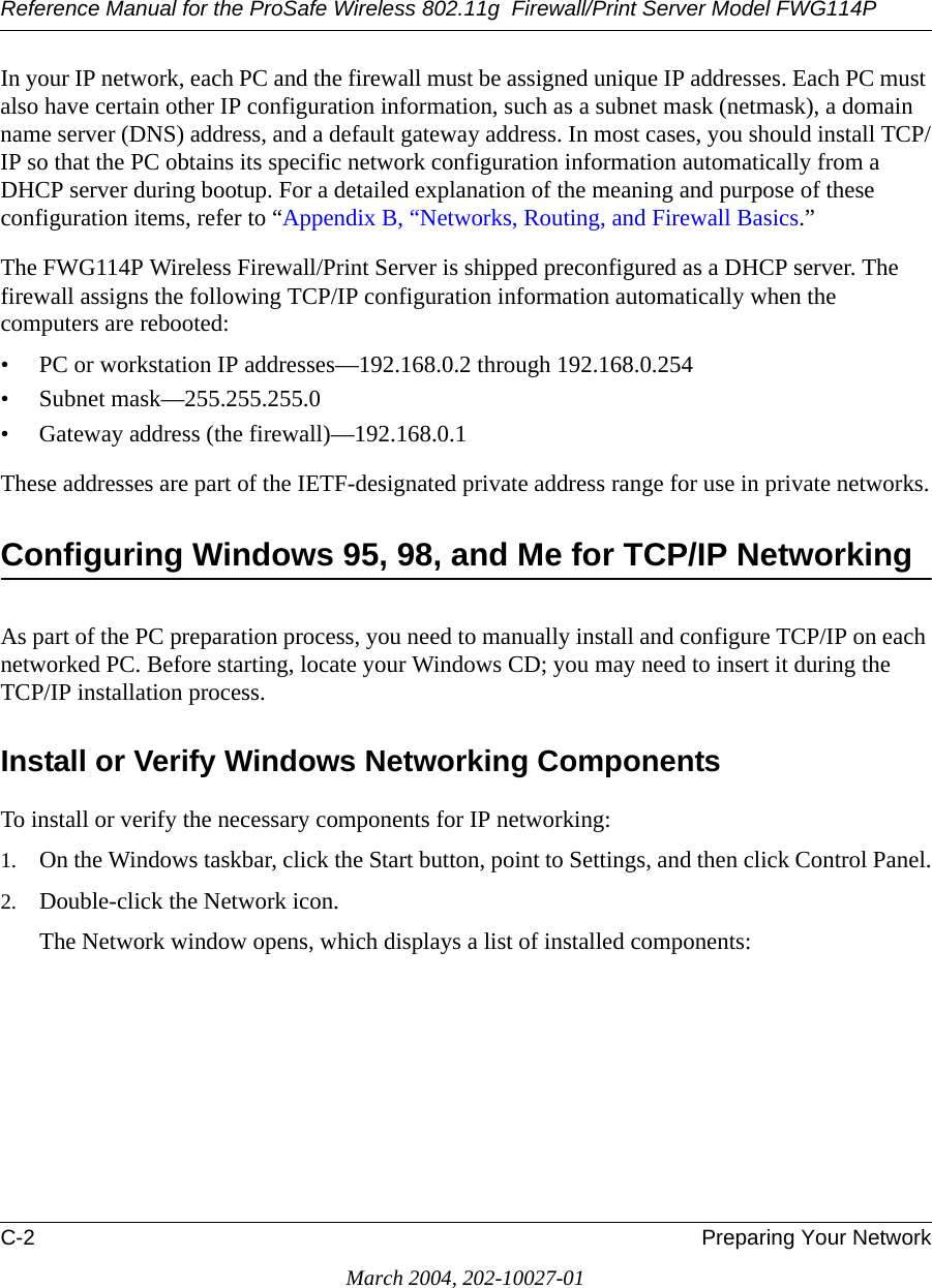
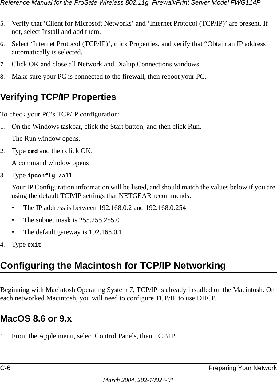
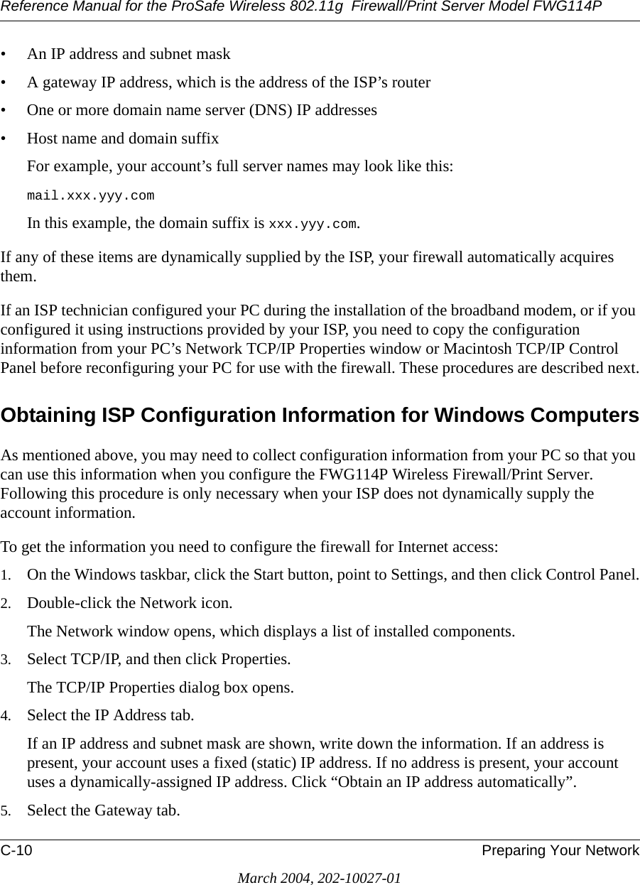
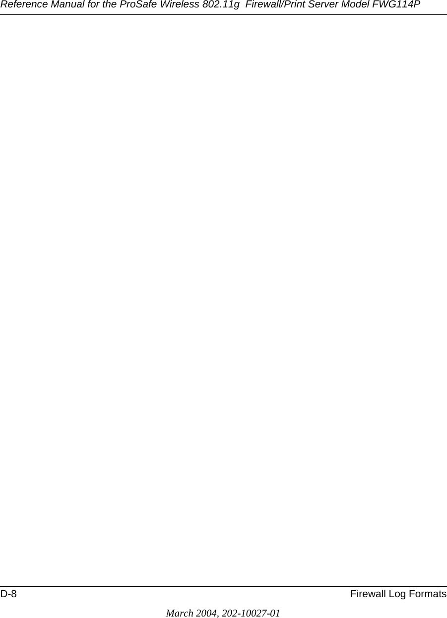
![Reference Manual for the ProSafe Wireless 802.11g Firewall/Print Server Model FWG114PD-4 Firewall Log FormatsMarch 2004, 202-10027-01Other Connections and Traffic to this RouterThe format is:<DATE><TIME>< PKT_TYPE ><SRC_IP><DST_IP><ACTION>[Fri, 2003-12-05 22:31:27] - ICMP Packet[Echo Request] - Source: 192.168.0.10 - Destination: 192.168.0.1 - [Receive][Wed, 2003-07-30 16:34:56] - ICMP Packet[Type: 238] - Source: 64.3.3.201 - Destination: 192.168.0.3 - [Drop][Fri, 2003-12-05 22:59:56] - ICMP Packet[Echo Request] - Source:192.168.0.10 - Destination:192.168.0.1 - [Receive]The format is:<DATE><TIME><EVENT>< SRC_IP><SRC_PORT ><SRC_INF>< DST_IP><DST_PORT><DST_INF><ACTION>[Wed, 2003-07-30 16:24:23] - UDP Packet - Source: 207.46.130.100 WAN - Destination: 10.10.10.4,1234 LAN - [Drop][Wed, 2003-07-30 17:48:09] - TCP Packet[SYN] - Source: 64.3.3.201,65534 WAN - Destination: 10.10.10.4,1765 LAN - [Receive][Fri, 2003-12-05 22:07:11] - IP Packet [Type Field:8], from 20.97.173.18 to 172.31.12.157 - [Drop]Notes:ACTION = "Drop", "Receive"EVENT = "ICMP Packet", "UDP Packet", "TCP Packet", "IP Packet"DoS Attack/ScanCommon attacks and scans are logged.](https://usermanual.wiki/Netgear-orporated/FWG114PV2.Users-Manual-Part-3/User-Guide-477792-Page-72.png)
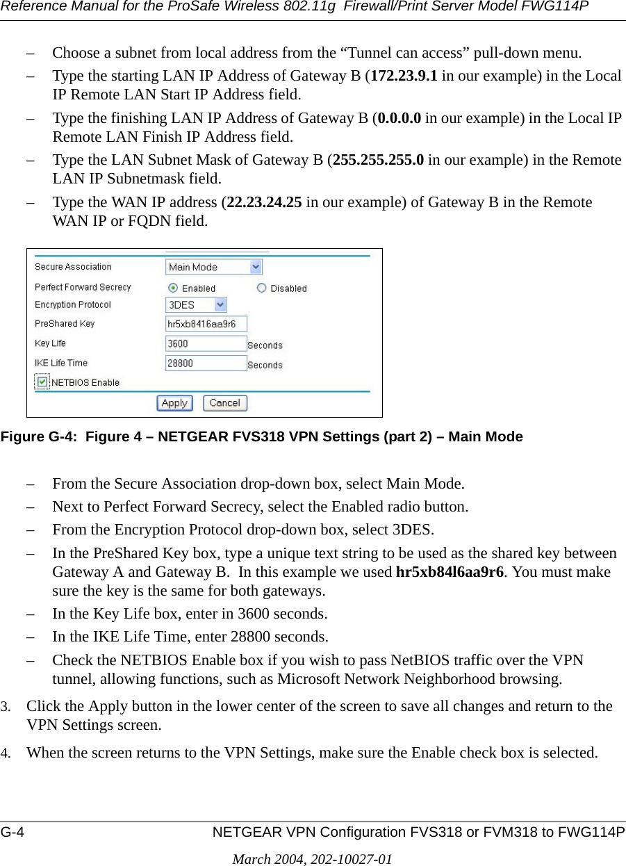
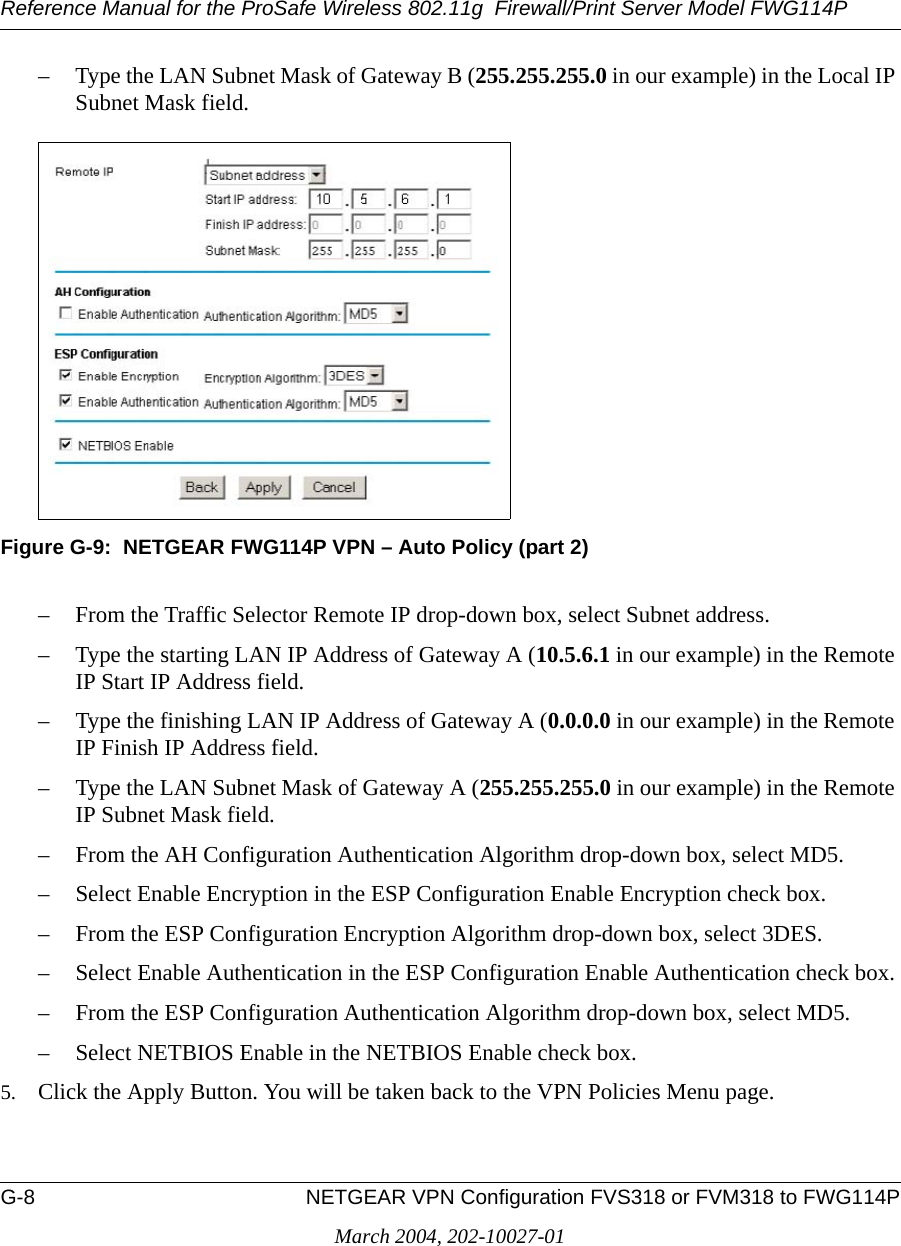
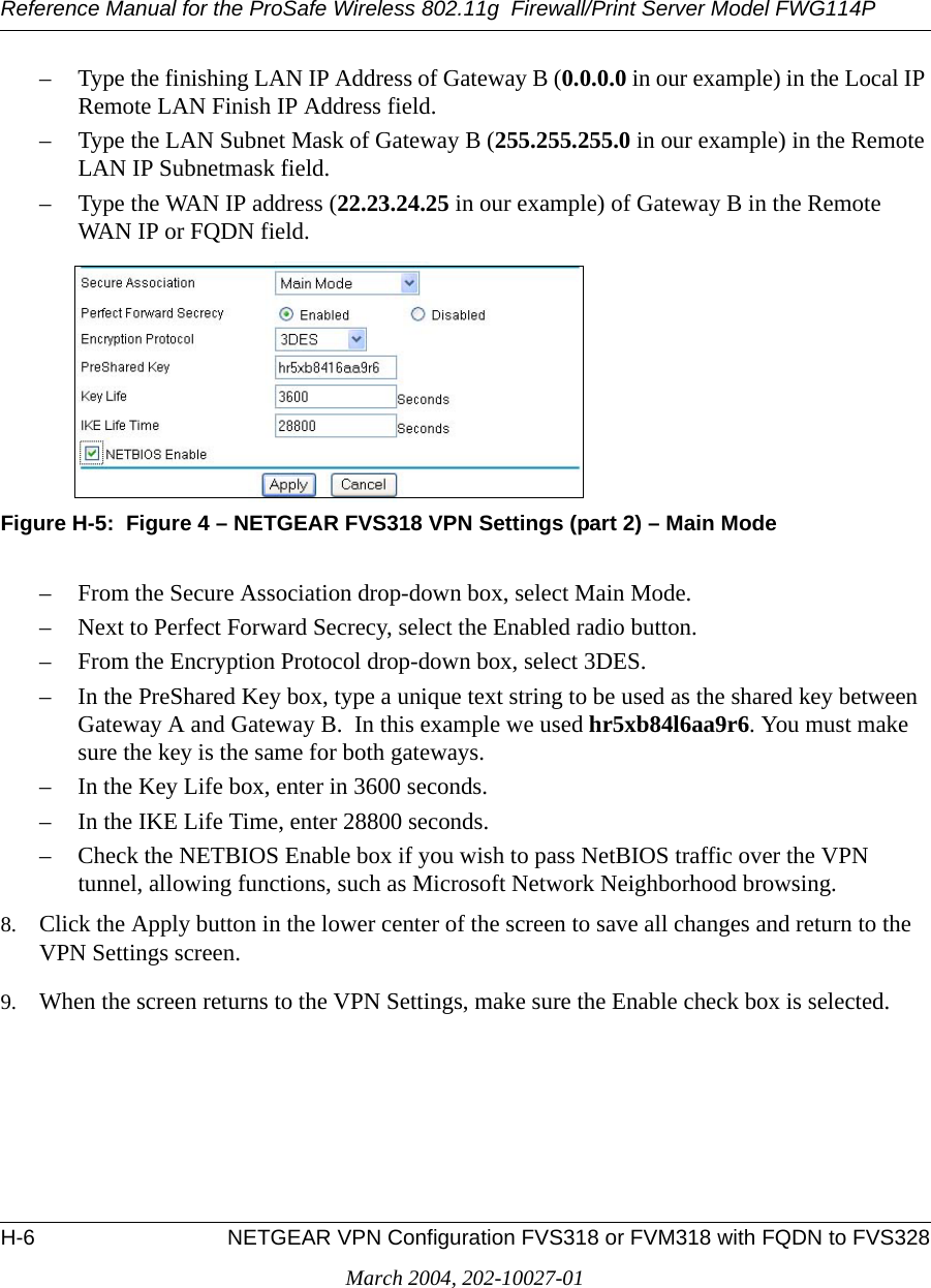
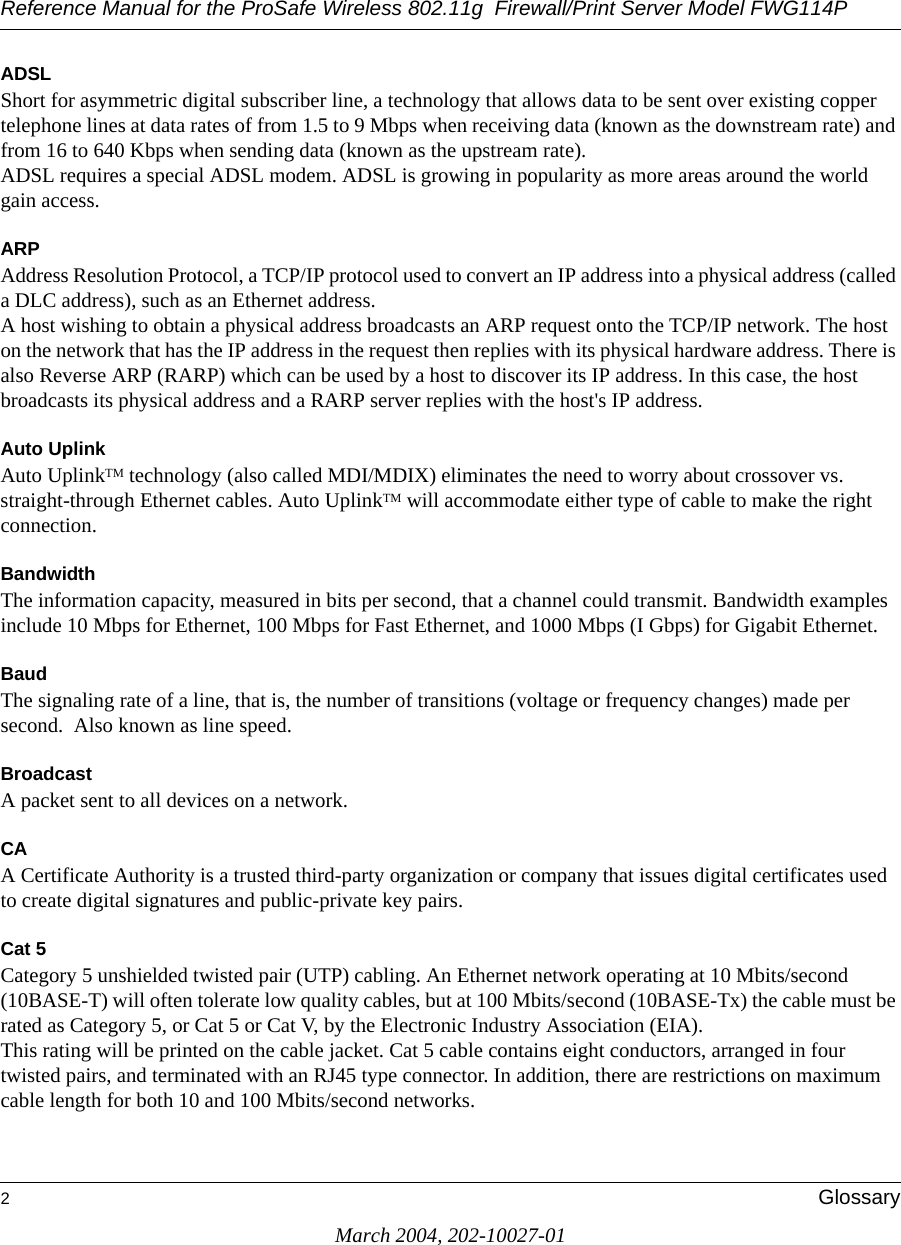
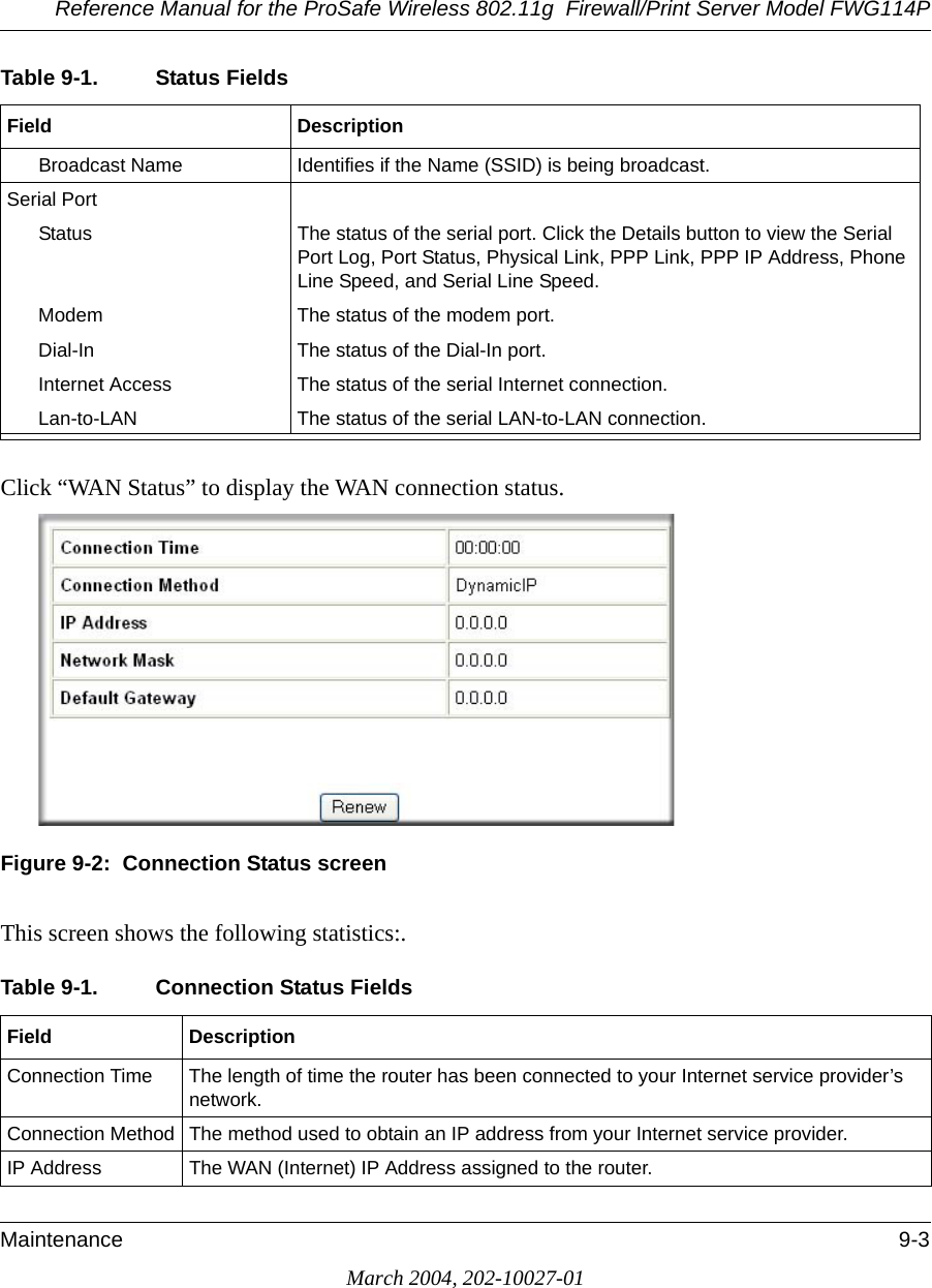
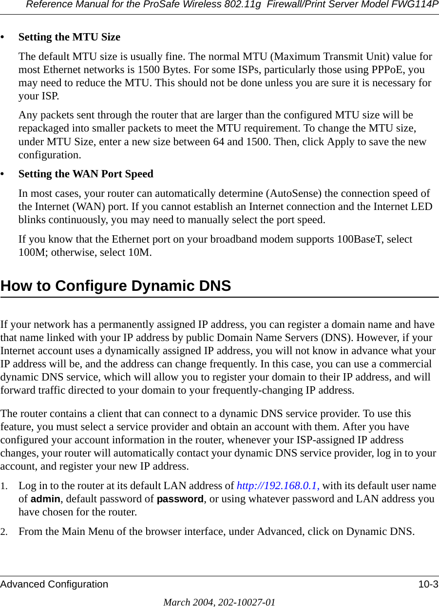
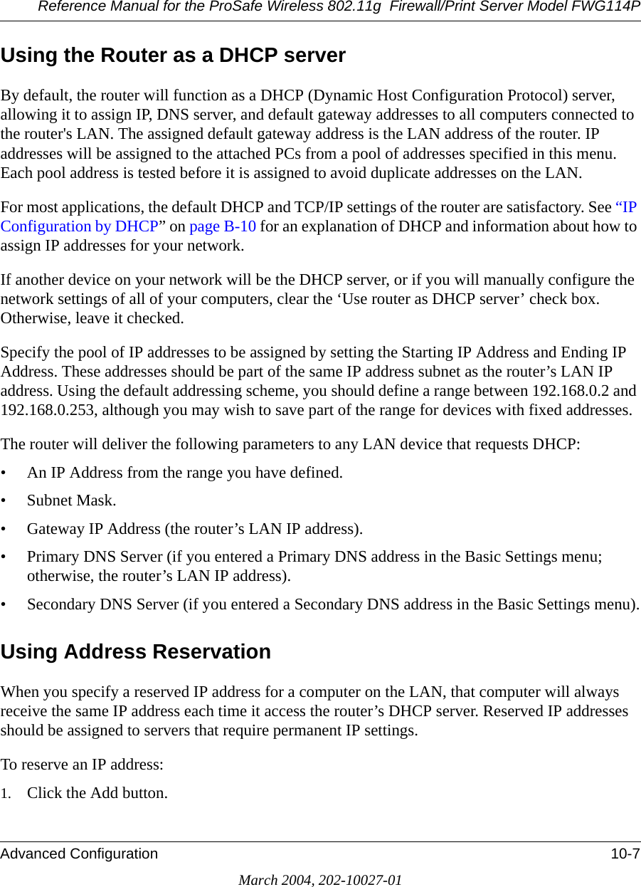
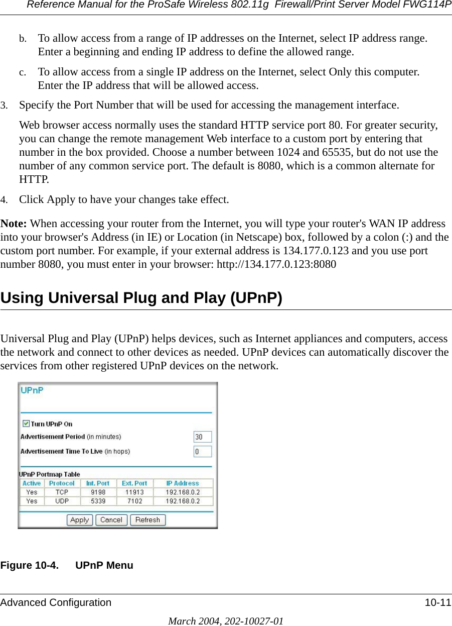
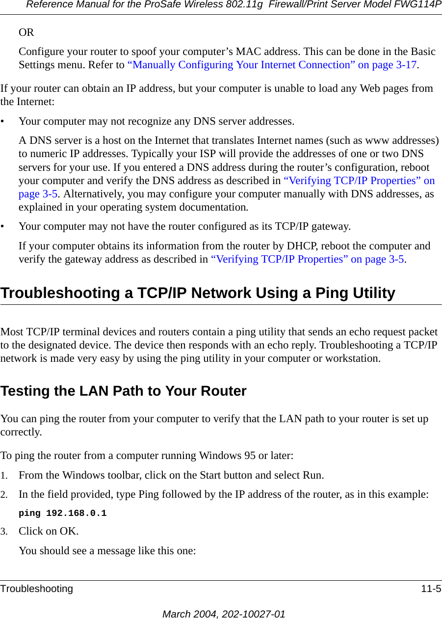
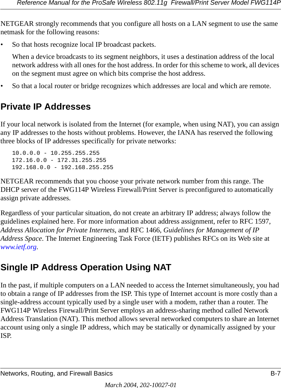
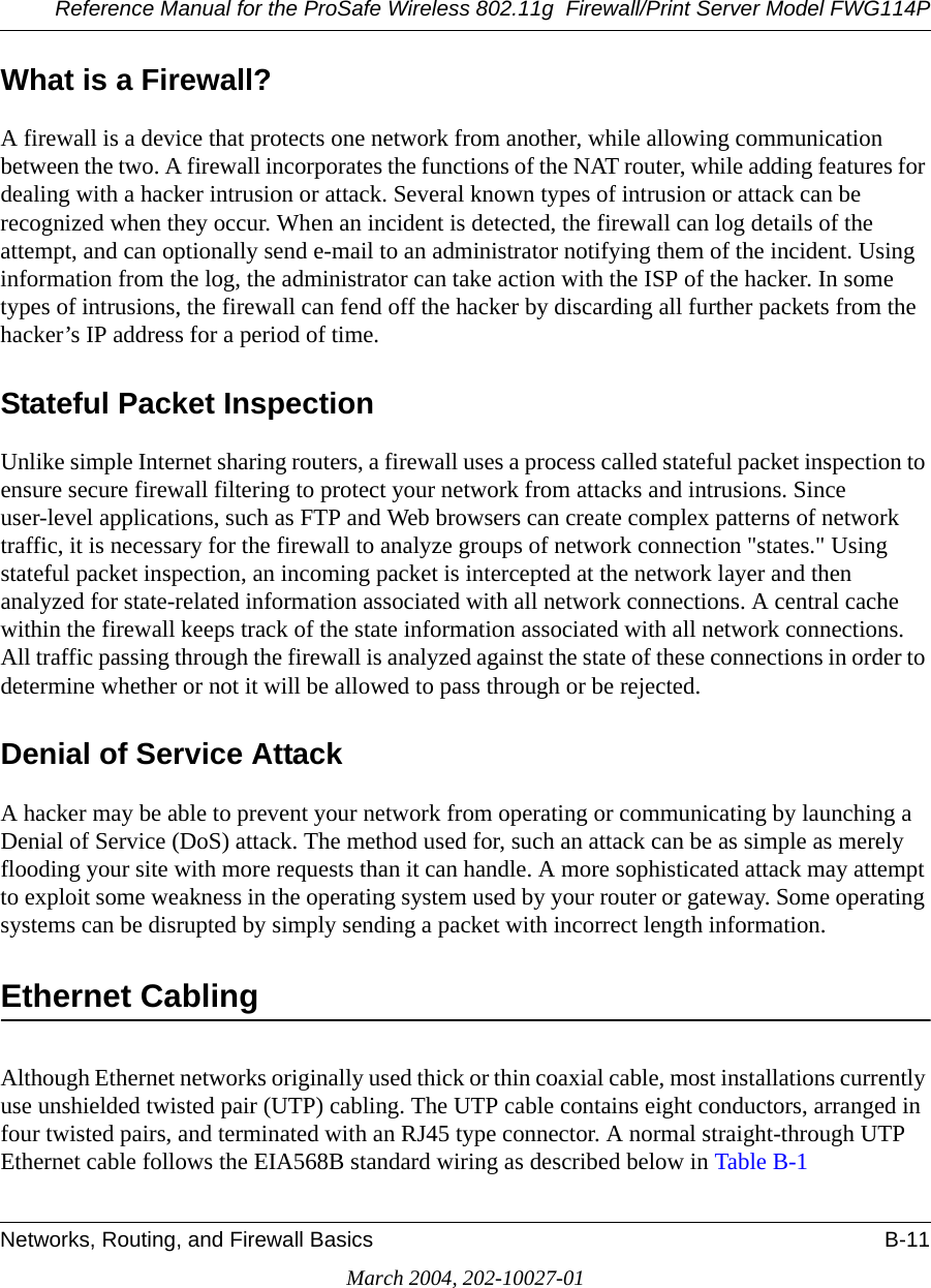
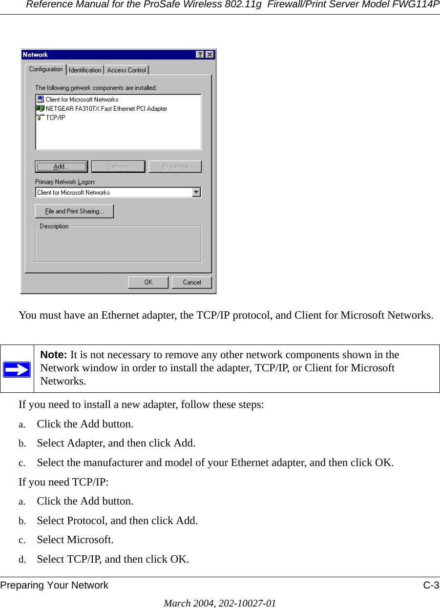
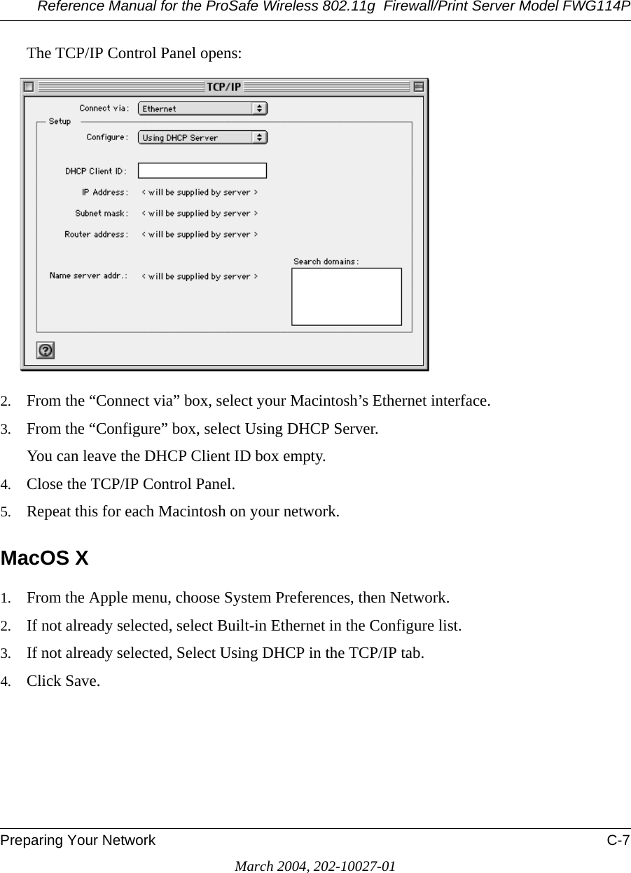
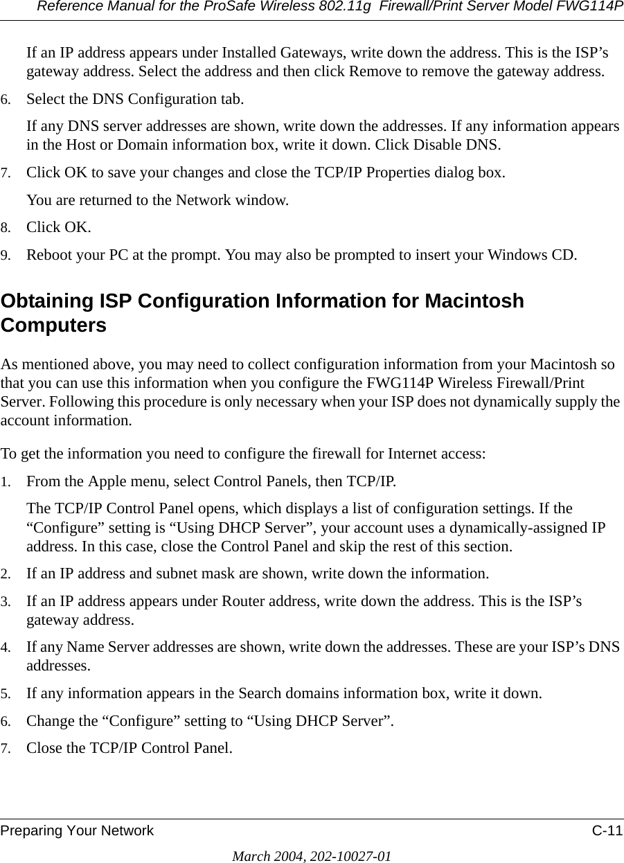
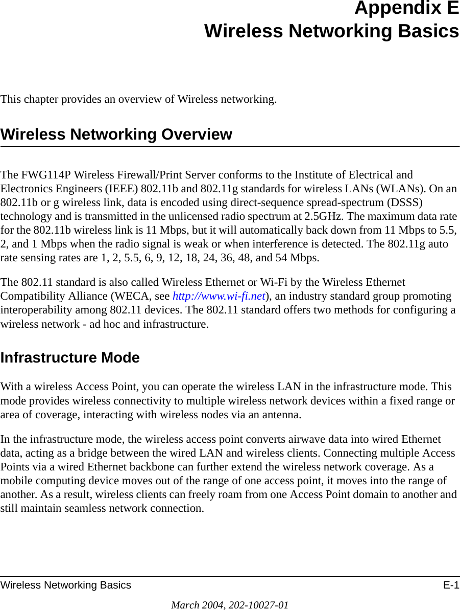
![Reference Manual for the ProSafe Wireless 802.11g Firewall/Print Server Model FWG114PFirewall Log Formats D-5March 2004, 202-10027-01The format is:<DATE><TIME><PKT_TYPE>< SRC_IP><SRC_PORT ><SRC_INF>< DST_IP><DST_PORT ><DST_PORT><ACTION><DESCRIPTION><DATE> <TIME> <PKT_TYPE> <SRC_IP> <SRC_INF> <DST_IP> <DST_INF> <ACTION> <DESCRIPTION>[Fri, 2003-12-05 21:22:07] - TCP Packet - Source:172.31.12.156,54611 ,WAN - Destination:172.31.12.157,134 ,LAN [Drop] - [FIN Scan][Fri, 2003-12-05 21:22:38] - TCP Packet - Source:172.31.12.156,59937 ,WAN - Destination:172.31.12.157,670 ,LAN [Drop] - [Nmap Xmas Scan][Fri, 2003-12-05 21:23:06] - TCP Packet - Source:172.31.12.156,39860 ,WAN - Destination:172.31.12.157,18000 ,LAN [Drop] - [Null Scan][Fri, 2003-12-05 21:27:55] - TCP Packet - Source:172.31.12.156,38009 ,WAN - Destination:172.31.12.157,15220 ,LAN [Drop] - [Full Sapu Scan][Fri, 2003-12-05 21:28:56] - TCP Packet - Source:172.31.12.156,35128 ,WAN - Destination:172.31.12.157,38728 ,LAN [Drop] - [Full Xmas Scan][Fri, 2003-12-05 21:30:30] - IP Packet - Source:227.113.223.77,WAN - Destination:172.31.12.157,LAN [Drop] - [Fragment Attack][Fri, 2003-12-05 21:30:30] - IP Packet - Source:20.97.173.18,WAN - Destination:172.31.12.157,LAN [Drop] - [Targa3 Attack][Fri, 2003-12-05 21:30:30] - TCP Packet - Source:3.130.176.84,37860 ,WAN - Destination:172.31.12.157,63881 ,LAN [Drop] - [Vecna Scan][Fri, 2003-12-05 21:30:31] - ICMP Packet [Type 238] - Source:100.110.182.63,WAN - Destination:172.31.12.157,LAN [Drop] - [ICMP Flood][Fri, 2003-12-05 21:33:52] - UDP Packet - Source:127.0.0.1,0 ,WAN - Destination:172.31.12.157,0 ,LAN [Drop] - [Fragment Attack][Fri, 2003-12-05 19:20:00] - TCP Session - Source:54.148.179.175,58595 ,LAN - Destination:192.168.0.1,20[FTP Data] ,WAN [Reset] - [SYN Flood][Fri, 2003-12-05 19:21:22] - UDP Packet - Source:172.31.12.156,7 ,LAN - Destination:172.31.12.157,7 ,WAN [Drop] - [UDP Flood][Fri, 2003-12-05 20:59:08] - ICMP Echo Request packet - Source:192.168.0.5,LAN - Destination:172.31.12.99,WAN [Drop] - [ICMP Flood][Fri, 2003-12-05 18:07:29] - TCP Packet - Source:192.168.0.10,1725 ,LAN - Destination:61.177.58.50,1352 ,WAN [Drop] - [TCP incomplete sessions overflow][Fri, 2003-12-05 21:11:24] - TCP Packet - Source:192.168.0.10,2342 ,LAN - Destination:61.177.58.50,1352 ,WAN [Drop] - [First TCP Packet not SYN]Notes:DESCRIPTION = "SYN Flood", "UDP Flood", "ICMP Flood", "IP Spoofing", "TearDrop", "Brute Force", "Ping of Death", "Fragment Attack", "Targa3 Attack", "Big Bomb""SYN with Data", "Full Xmas Scan", "Full Head Scan", "Full Sapu Scan", "FIN Scan", "SYN FIN Scan", "Null Scan", "Nmap Xmas Scan", "Vecna Scan", "Tcp SYN RES Set", "Other Scan""TCP incomplete sessions overflow", "TCP preconnect traffic", "TCP invalid traffic", "First TCP Packet not SYN", "First TCP Packet with no SYN"<DATE><TIME><PKT_TYPE>< SRC_IP >< DST_IP><ACTION>[Wed, 2003-07-30 17:45:17] - TCP Packet [Malformed, Length=896] - Source: 64.3.3.201 - Destination: 10.10.10.4 - [Drop][Wed, 2003-07-30 17:45:17] - TCP Packet [Malformed, Length=1000] - Source: 64.3.3.201- Destination: 10.10.10.4 - [Forward]Notes:PKT_TYPE = "TCP", "UDP", "ICMP", "Proto: Number"](https://usermanual.wiki/Netgear-orporated/FWG114PV2.Users-Manual-Part-3/User-Guide-477792-Page-73.png)
![Reference Manual for the ProSafe Wireless 802.11g Firewall/Print Server Model FWG114PD-6 Firewall Log FormatsMarch 2004, 202-10027-01Access Block SiteIf keyword blocking is enabled and a keyword is specified, attempts to access a site whose URL contains a specified keyword are logged. The format is <DATE> <TIME> <EVENT> <SRC_IP> <SRC_INF> <DST_IP> <DST_INF> <ACTION>[Fri, 2003-12-05 23:01:47] - Attempt to access blocked sites - Source:192.168.0.10,LAN - Destination:www.google.com/,WAN - [Drop]Notes:EVENT = Attempt to access blocked sitesSRC_INF = LANDST_INF = WANAll Web Sites and News Groups Visited All Web sites and News groups that you visit are logged.The format is<DATE> <TIME> <EVENT> <SRC_IP> <SRC_INF> <DST_IP> <DST_INF> <ACTION>[Fri, 2003-12-05 23:03:49] - Access site - Source:192.168.0.10,LAN - Destination:euro.allyes.com,WAN - [Forward]Notes:EVENT = Attempt to access blocked sitesSRC_INF = LAN or WANDST_INF = WAN or LANSystem Admin SessionsAdministrator session logins and failed attempts are logged, as well as manual or idle-time logouts.](https://usermanual.wiki/Netgear-orporated/FWG114PV2.Users-Manual-Part-3/User-Guide-477792-Page-74.png)
![Reference Manual for the ProSafe Wireless 802.11g Firewall/Print Server Model FWG114PFirewall Log Formats D-7March 2004, 202-10027-01The format is: <DATE><TIME><EVENT ><SRC_IP><DATE><TIME><EVENT ><SRC_IP><SRC_PORT><DST_IP><DST_PORT><ACTION>[Fri, 2003-12-05 21:07:43] - Administrator login successful - IP:192.168.0.10[Fri, 2003-12-05 21:09:16] - Administrator logout - IP:192.168.0.10[Fri, 2003-12-05 21:09:31] - Administrator login fail, Username error - IP:192.168.0.10[Fri, 2003-12-05 21:09:25] - Administrator login fail, Password error - IP:192.168.0.10[Fri, 2003-12-05 21:16:15] - Login screen timed out - IP:192.168.0.10[Fri, 2003-12-05 21:07:43] - Administrator Interface Connecting[TCP] - Source 192.168.0.10,2440 - Destination 192.168.0.1,80 - [Receive]Notes:ACTION: Receive or DropPolicy Administration LOG<DATE> <TIME> <EVENT> <DIRECTION> <SERVICE>< DESCRIPTION >[Fri, 2003-12-05 21:48:41] - Administrator Action - Inbound Policy to Service [BGP] is Added[Fri, 2003-12-05 21:49:41] - Administrator Action - Outbound Policy to Service [BGP] is Added[Fri, 2003-12-05 21:50:14] - Administrator Action - Inbound Policy to Service [BGP] is Modified[Fri, 2003-12-05 21:50:57] - Administrator Action - Outbound Policy to Service [BGP] is Modified[Fri, 2003-12-05 21:51:14] - Administrator Action - Inbound Policy to Service [BGP] is Deleted[Fri, 2003-12-05 21:52:12] - Administrator Action - Inbound Policy to Service [BGP] is Moved to Index [0][Fri, 2003-12-05 21:54:41] - Administrator Action - Outbound Policy to Service [FTP] is Moved to Index [1][Fri, 2003-12-05 22:01:47] - Administrator Action - Inbound Policy to Service [BGP] is changed to Disable[Fri, 2003-12-05 22:02:14] - Administrator Action - Inbound Policy to Service [BGP] is changed to Enable[Fri, 2003-12-05 22:02:35] - Administrator Action - Outbound Policy to Service [NFS] is changed to Disable[Fri, 2003-12-05 22:02:52] - Administrator Action - Outbound Policy to Service [NFS] is changed to EnableNotes:DIRECTION: Inbound or OutboundSERVICE: Supported service name](https://usermanual.wiki/Netgear-orporated/FWG114PV2.Users-Manual-Part-3/User-Guide-477792-Page-75.png)
![Reference Manual for the ProSafe Wireless 802.11g Firewall/Print Server Model FWG114PVirtual Private Networking F-11March 2004, 202-10027-01VPNC IKE Phase II ParametersThe IKE Phase 2 parameters used in Scenario 1 are: •TripleDES• SHA-1• ESP tunnel mode • MODP group 1 • Perfect forward secrecy for rekeying • SA lifetime of 28800 seconds (one hour)Testing and TroubleshootingOnce you have completed the VPN configuration steps you can use PCs, located behind each of the gateways, to ping various addresses on the LAN side of the other gateway.You can troubleshoot connections using the VPN status and log details on the NETGEAR gateway to determine if IKE negotiation is working. Common problems encountered in setting up VPNs include:• Parameters may be configured differently on Gateway A vs. Gateway B.• Two LANs set up with similar or overlapping addressing schemes.• So many required configuration parameters mean errors such as mistyped information or mismatched parameter selections on either side are more likely to happen. Additional Reading•Building and Managing Virtual Private Networks, Dave Kosiur, Wiley & Sons; ISBN: 0471295264•Firewalls and Internet Security: Repelling the Wily Hacker, William R. Cheswick and Steven M. Bellovin, Addison-Wesley; ISBN: 0201633574•VPNs A Beginners Guide, John Mains, McGraw Hill; ISBN: 0072191813• [FF98] Floyd, S., and Fall, K., Promoting the Use of End-to-End Congestion Control in the Internet. IEEE/ACM Transactions on Networking, August 1999.Relevant RFCs listed numerically:](https://usermanual.wiki/Netgear-orporated/FWG114PV2.Users-Manual-Part-3/User-Guide-477792-Page-105.png)
![Reference Manual for the ProSafe Wireless 802.11g Firewall/Print Server Model FWG114PF-12 Virtual Private NetworkingMarch 2004, 202-10027-01• [RFC 791] Internet Protocol DARPA Internet Program Protocol Specification, Information Sciences Institute, USC, September 1981.• [RFC 1058] Routing Information Protocol, C Hedrick, Rutgers University, June 1988.• [RFC 1483] Multiprotocol Encapsulation over ATM Adaptation Layer 5, Juha Heinanen, Telecom Finland, July 1993.• [RFC 2401] S. Kent, R. Atkinson, Security Architecture for the Internet Protocol, RFC 2401, November 1998.• [RFC 2407] D. Piper, The Internet IP Security Domain of Interpretation for ISAKMP, November 1998.• [RFC 2474] K. Nichols, S. Blake, F. Baker, D. Black, Definition of the Differentiated Services Field (DS Field) in the IPv4 and IPv6 Headers, December 1998.• [RFC 2475] S. Blake, D. Black, M. Carlson, E. Davies, Z. Wang, and W. Weiss, An Architecture for Differentiated Services, December 1998.• [RFC 2481] K. Ramakrishnan, S. Floyd, A Proposal to Add Explicit Congestion Notification (ECN) to IP, January 1999.• [RFC 2408] D. Maughan, M. Schertler, M. Schneider, J. Turner, Internet Security Association and Key Management Protocol (ISAKMP).• [RFC 2409] D. Harkins, D.Carrel, Internet Key Exchange (IKE) protocol.• [RFC 2401] S. Kent, R. Atkinson, Security Architecture for the Internet Protocol.](https://usermanual.wiki/Netgear-orporated/FWG114PV2.Users-Manual-Part-3/User-Guide-477792-Page-106.png)