Navtech Radar TS350X-001 TS350-X Position Sensing Radar User Manual User Guide 2
Navtech Radar Ltd TS350-X Position Sensing Radar User Guide 2
UserManual.wiki
>
Navtech Radar
>
TS350X-001 User Manual
>
User Guide 2
Contents
1.
User Guide 1
2.
User Guide 2
User Guide 2
Navigation menu
Upload a User Manual
Namespaces
Wiki Guide
HTML
PDF
Info
Views
User Manual
Discussion / Help
Navigation

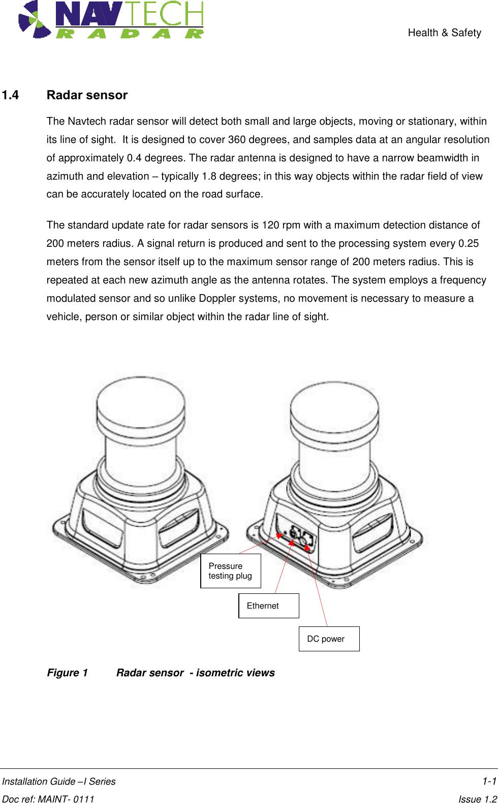
![Introduction Installation Guide –I Series 1-1 Doc ref: MAINT- 0111 Issue 1.2 1. Introduction 1.1 Scope The Navtech SafeGuard Detection system provides an automatic monitoring solution for open areas such as airports, outdoor industrial machines and vehicles that commonly operate in ports, mines or other industrial areas. The SafeGuard system comprises a high frequency radar sensor, linked to a software system, witness. This guide provides instruction for the radar sensor installation ONLY. The installation of the witness application is covered separately in [2]. Service and Maintenance procedures are also covered separately in [3]. The instructions in this guide are applicable to the following Navtech radar sensors: I 200 I 500 Details are provided for all the hardware components required for the installation. 1.2 Essential Items The following are essential additional items that you need to install a radar sensor: (i) Electrical Power Electrical power (110 to 230vAC) sourced from, for example, local mains. 110 to 230vAC power is required for the Radar’s 24vDC PSU. - 110 to 230vAC power is also required for the Laptop Computer used during the commissioning process. Note: Radars are network intensive. Some laptops reduce the performance of their network connection when only running on their internal battery. (ii) A way of working safely at height Most Container Cranes and Bulks Loader have walkways with hand rails - keeping to within the confines of these hand rails, will keep you relatively safe. However this does depend on the specific machine or site you are working on. If required to do wear a harness and fall arrestor – Make sure you clip on to a secure structure or on to a dedicated cable/SWR rope. Make sure any equipment used conforms to: Shock Absorbing Lanyards – EN354/355 Harnesses – EN361/prEN1496/1497/1498/020895 Retractable Type Fall Arrester - EN360](https://usermanual.wiki/Navtech-Radar/TS350X-001.User-Guide-2/User-Guide-1970752-Page-6.png)
![Introduction Installation Guide –I Series 1-2 Doc ref: MAINT- 0111 Issue 1.2 (iii) Laptop computer The laptop should have: - RJ45 Ethernet connection. - 9 pin Com port or USB to RS232 adapter [Optional] - Software – SPxRadarViewLite-V1.47.1 or higher - Serial communication software – e.g. HyperTerminal, TeraTerm, Putty. (iv) Cat5E shielded patch lead (or Cross over cable, if laptop doesn’t have Auto-MDIX) (v) M10 nuts and bolts for mounting radar The minimum for one radar, in A4 Stainless Steel. - x4 off M10x80 HEX Set Screw - x4 off M10 spring washers - x4 off M10 plain washers - x4 off Nyloc Nuts - x12 off M10 Full plain nuts - x2 off 17mm Spanner for the M10 nuts and bolts above. (vi) 5m tape measure (vii) Digital Level1 (viii) 25m² Trihedral Radar Target (ix) Pair of 2 way radios (x) An assistant (xi) Power Supply cable (Minimum Requirement) - see 0Table 2 for specification, or Inline Radar Power, Serial and Current Cable (Optional) - see [3]. 1.3 Pre requisites to working on a Container Crane & Bulk Loaders Follow local Health and Safety guidelines, as determined by local safety management procedures. Navtech training courses are available, offering practical advice and recommendations on how to successfully install and commission the SafeGuard products 1 Recommended Fisco Solatronic EN17](https://usermanual.wiki/Navtech-Radar/TS350X-001.User-Guide-2/User-Guide-1970752-Page-7.png)
![Health & Safety Installation Guide –I Series 1-2 Doc ref: MAINT- 0111 Issue 1.2 Figure 2 Radar sensor - dimensions See [D1] for further details on the radar housing. Each radar is supplied with a Power cable assembly[10] and an Ethernet environmental shell (which fits over a standard RJ45 to provide an IP67 seal). Further connector detail in Annex C](https://usermanual.wiki/Navtech-Radar/TS350X-001.User-Guide-2/User-Guide-1970752-Page-9.png)
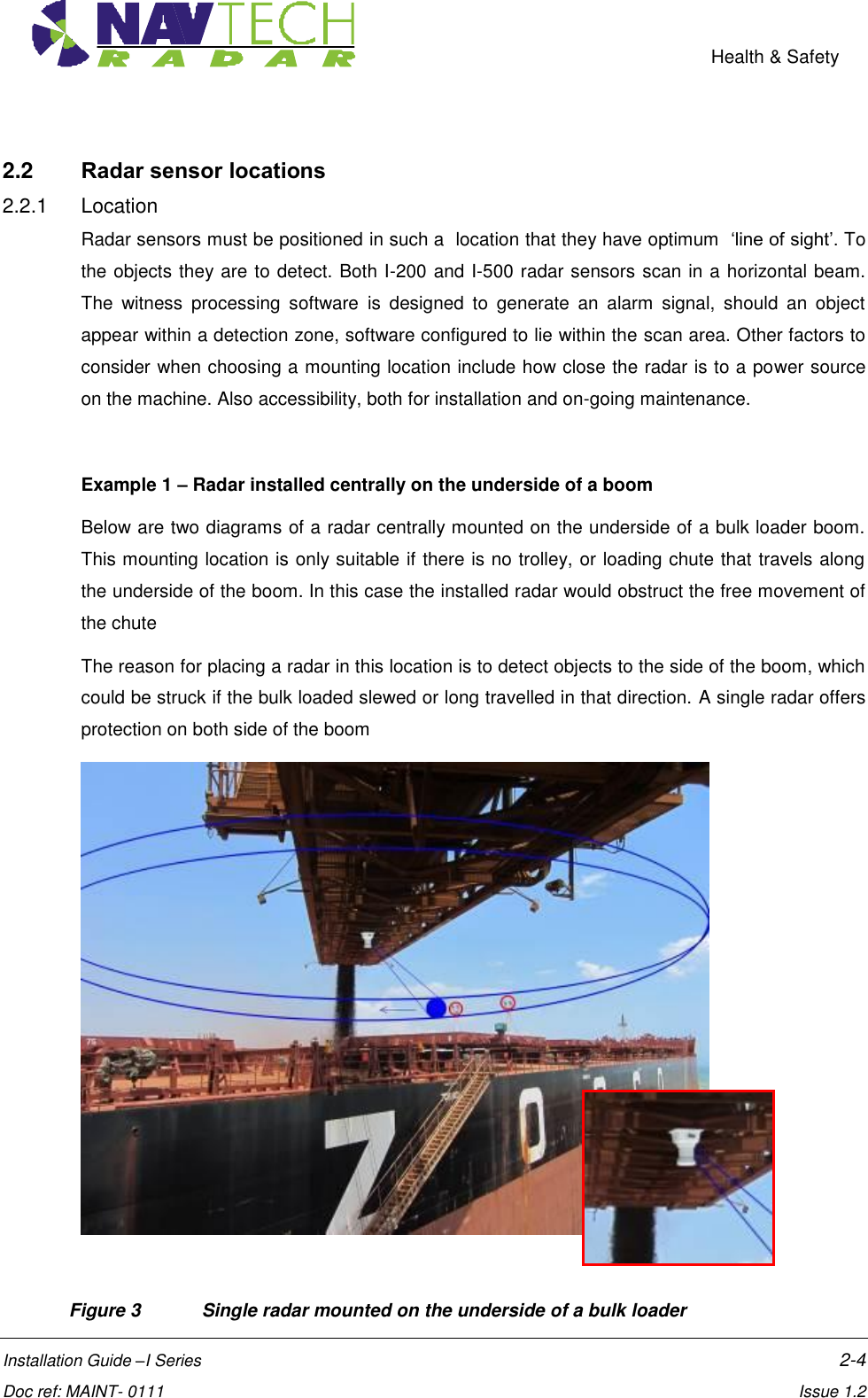
![Health & Safety Installation Guide –I Series 2-3 Doc ref: MAINT- 0111 Issue 1.2 2. Installing the Radar hardware 2.1 Overview This section details the installation process, which comprises the following steps: 1. Determine radar sensor locations 2. Mount radar 3. Connect radar sensor 4. Prepare laptop 5. Connect laptop 6. Level radar sensor 7. Install Navtech witness software 8. Confirm sensor coverage Note: The installation and configuration of the witness software is covered separately in [2]. CAUTION Before performing any installation task ensure you are aware of Health & Safety procedures. (See Section 0)](https://usermanual.wiki/Navtech-Radar/TS350X-001.User-Guide-2/User-Guide-1970752-Page-10.png)
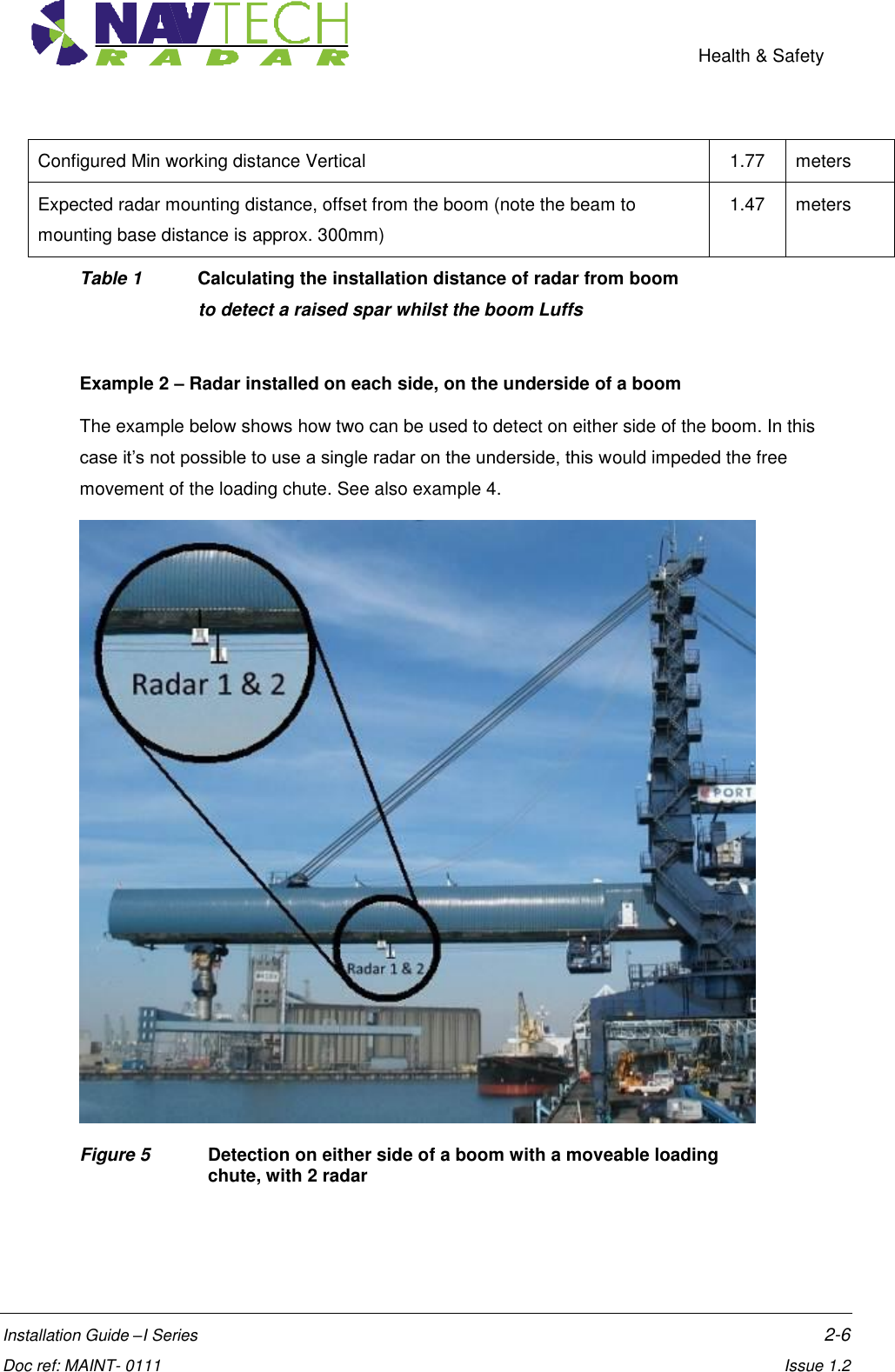
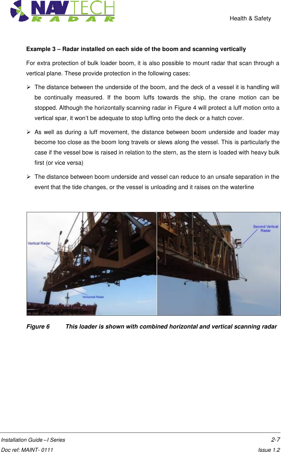
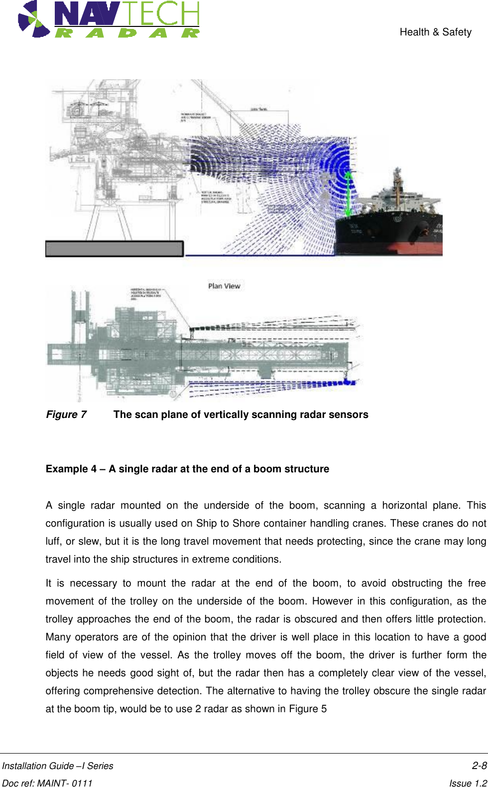
![Health & Safety Installation Guide –I Series 2-5 Doc ref: MAINT- 0111 Issue 1.2 The primary use of the single radar scanning a horizontal plane is to protect slew and long travel. A secondary benefit though, is to stop the boom being lowered/luffed down on to an object that is raised above the deck level of a vessel. Although, this radar will not detect objects that are beneath the pane of the horizontal scan, as the boom luffs down these objects should be detected. Care should be taken to ensure the radar is mounted at a sufficient distance from the underside of the boom, so the luff motion can be stopped in time to prevent a collision. By considering the rate of luff of the boom; the scan rate of the radar (typically 2 rps); and the number of required detections configured in the witness processing software to generate a stop alarm; the ideal separation between radar and boom can be calculated. Figure 4 A single radar detects objects as the boom luffs Luff Operation - Vertical Radar Boom length 52 meters rate of turn on boom Luff 0.15 deg/sec velocity at the tip of the boom 0.14 meters/sec Radar detections configured in software processing, to raise a stop alarm 4 Time to detect, for a 2 Hz radar [4Hz option available] 2.0 Sec Luff meters moved at the boom tip, before full detection 0.27 meters Safety Margin, to accommodates the boom stopping distance 1.5 meters](https://usermanual.wiki/Navtech-Radar/TS350X-001.User-Guide-2/User-Guide-1970752-Page-12.png)
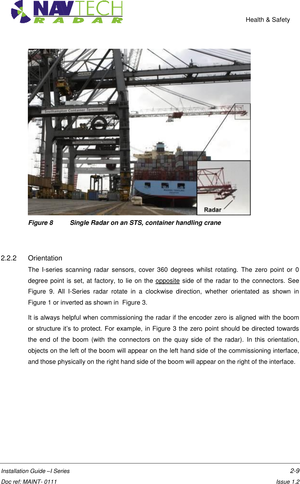
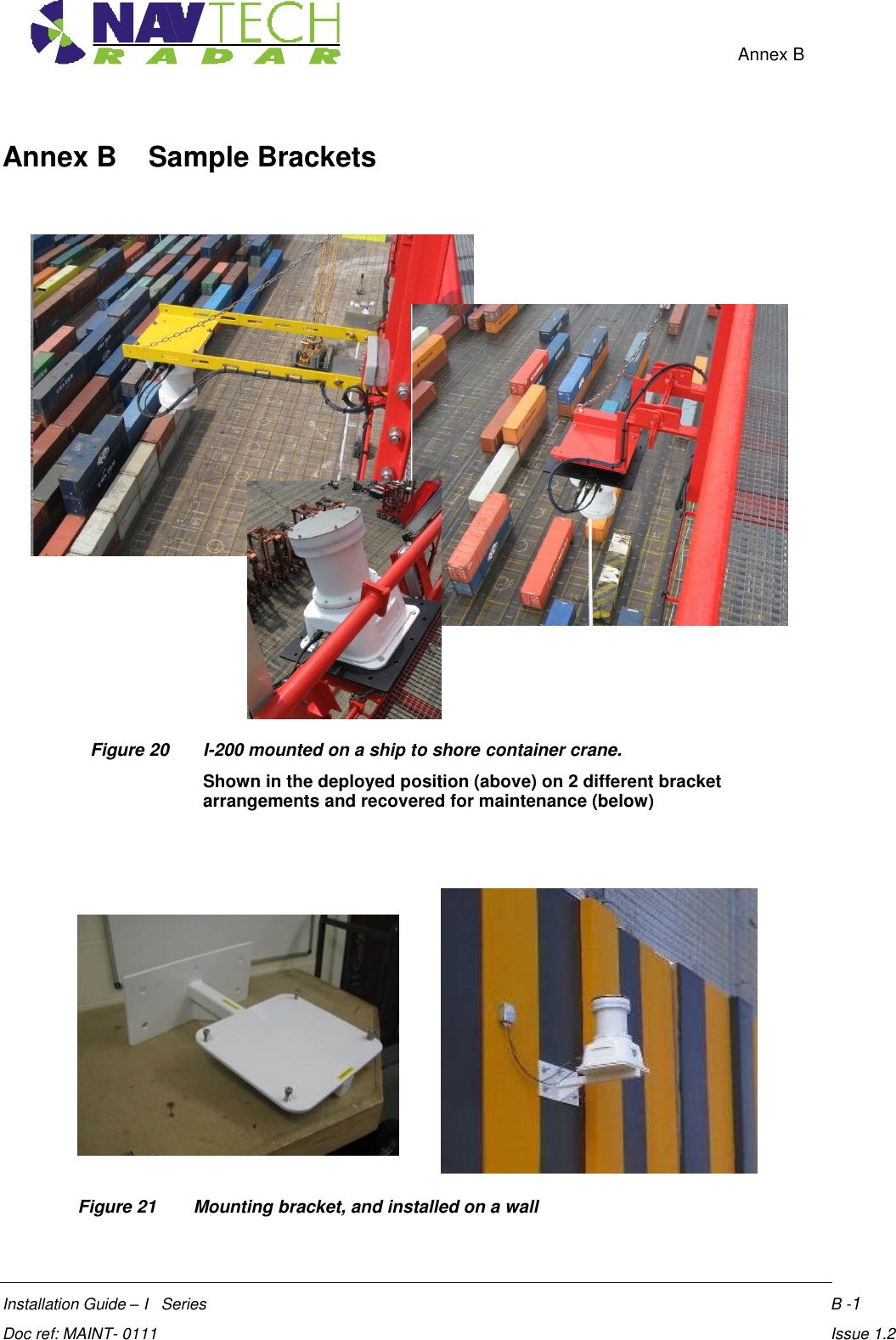
![Health & Safety Installation Guide –I Series 2-10 Doc ref: MAINT- 0111 Issue 1.2 Figure 9 Plan view of a radar, showing the encoder zero angle 2.3 Mounting radar sensor Radar sensors may be mounted on various structures (e.g walls, roofs, gantries) using brackets. Sample posts and brackets are shown in Annex B. Radar sensors are fitted to a plate on top of the post, or on the bracket, using nuts and bolts, which allows you to adjust the tilt [See Figure 11]. Adjusting the tilt (levelling the sensor) ensures optimum detection performance and is detailed in Section 2.7. Figure 10 Mounting radar on posts/brackets, for both vertical and horizontally scanning radar](https://usermanual.wiki/Navtech-Radar/TS350X-001.User-Guide-2/User-Guide-1970752-Page-17.png)
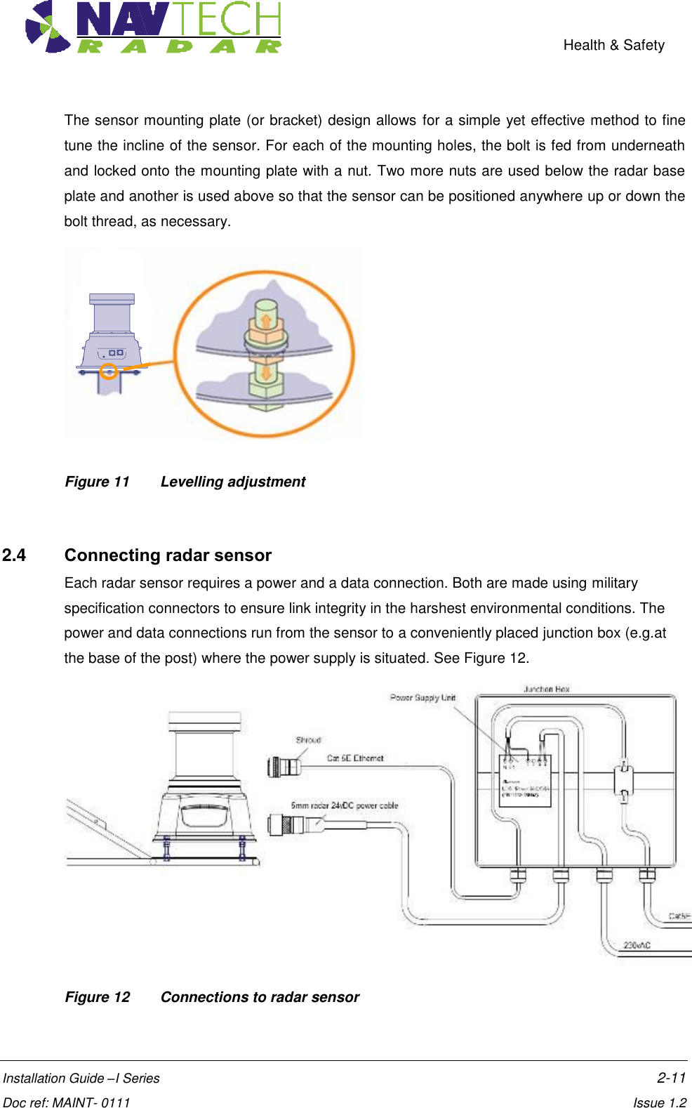
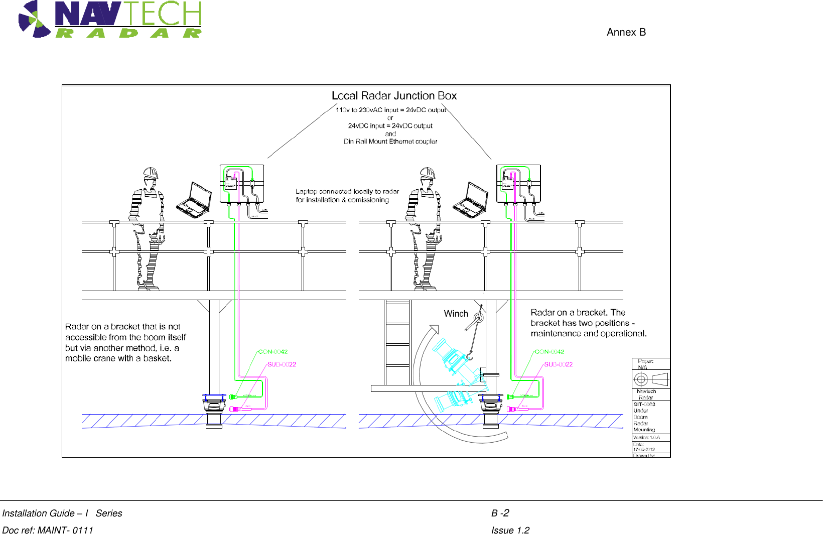
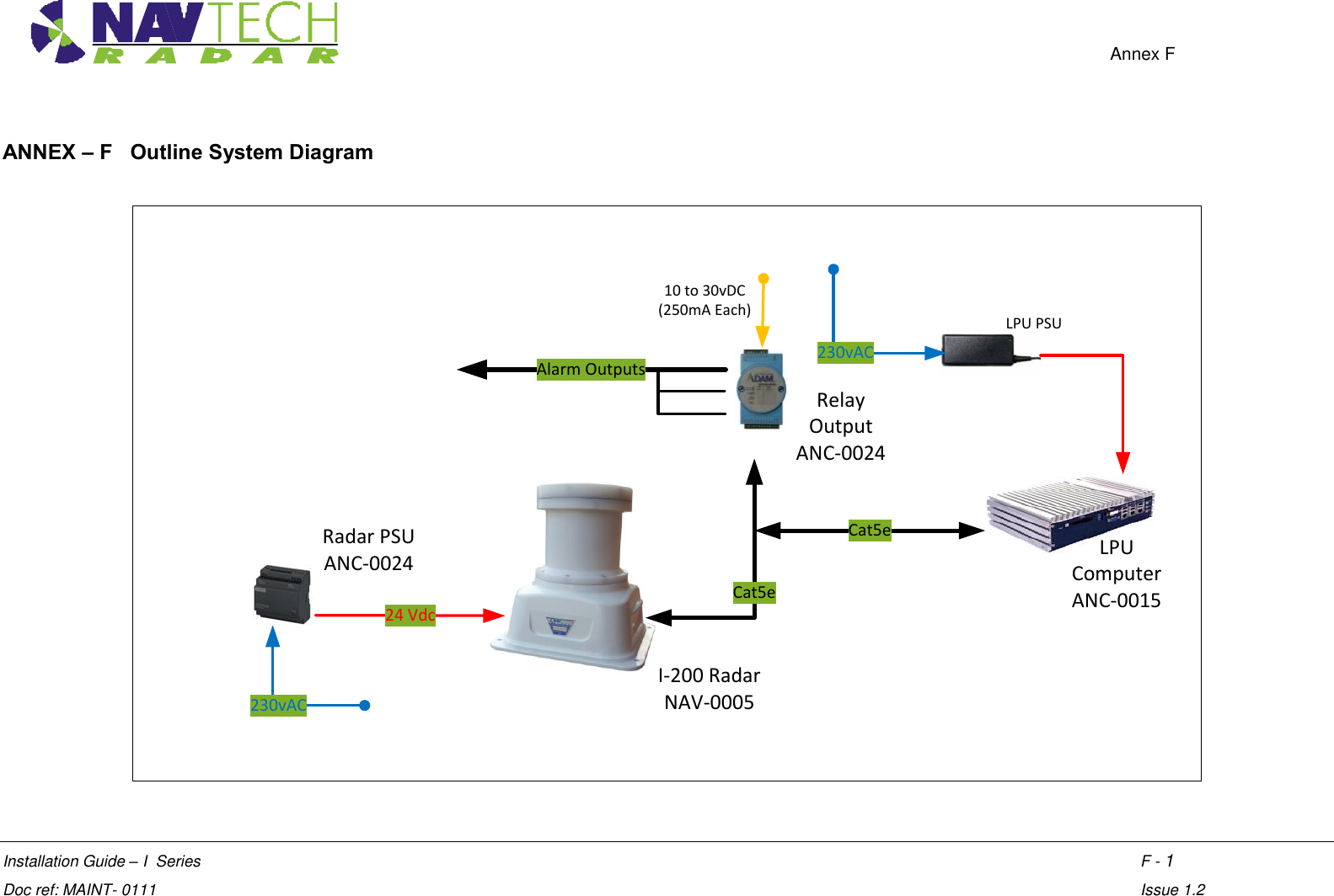
![Health & Safety Installation Guide –I Series 2-12 Doc ref: MAINT- 0111 Issue 1.2 Supplied with each radar sensor are a power cable with a mil-spec connector for the sensor connection and a bare end at the junction box connection. A mil spec shroud is also supplied for use with a suitable environmentally protected Ethernet network connection. It is essential that the supplied shroud is correctly used to ensure that the data connection is water tight. IMPORTANT: Failure to correctly fit the shroud can invalidate the warranty on sensors that have been caused to fail through water ingress. 1. Attach 24vDC connection to the radar. Figure 13 Connecting radar sensor 2. Ensure the Power and Ethernet cables are securely connected into junction box. 3. Ensure the junction box has the Navtech supplied 24vDC power supply installed. (The power supply unit has a peak current capacity of 4 Amps, though typically the radar draws a continuous 1 Amp). See.[8]. 4. Ensure that the Power supply cabling is correctly terminated at the radar end with a secure Amphenol MIL spec connector. Pin D (Red or Brown) is 24vDC, Pin J (Blue or Black) is 0V. IMPORTANT: To prevent floating voltage levels on the low output of the radar sensor power supply unit, link the 0v output to earth. 5. Ensure the junction box has an Ethernet cable running to the infrastructure network switch.](https://usermanual.wiki/Navtech-Radar/TS350X-001.User-Guide-2/User-Guide-1970752-Page-19.png)
![Health & Safety Installation Guide –I Series 2-13 Doc ref: MAINT- 0111 Issue 1.2 2.5 Preparing the laptop IMPORTANT: Ensure that your laptop has its IP address set to operate within the same subnet as the radar sensor 2.5.1 Factory settings The IP address (e.g. 192.168.0.1) of the radar sensor is preset before leaving Navtech Radar Limited according to client specifications and will be declared on a label attached to the outer casing. The subnet mask of the radar sensor is often preset to 255.255.255.0 but could also be set wider (such as 255.255.0.0) if requested. Therefore, if the sensor IP address is 192.168.0.1 and the mask is 255.255.255.0, then your computer must use an IP address in the range: 192.168.0.2 to 192.168.0.254. 2.5.2 Changing factory settings The IP address and subnet mask can be changed using firmware commands sent to the radar either via Telnet (see [5]), or using a serial connection (see [D3]). 2.6 Connecting your laptop 1. At the radar, connect the laptop via CAT5 cable to the radar. 2. Ensure that the radar sensor is powered on and is rotating - you can faintly hear the rotor when it is running. 3. Use SPx Radar View application [1] to display the radar data. (See Annex A ) 2.7 Levelling radar sensor For optimum detection performance it is important that each sensor is level in relation to the area that it surveys. Level in this sense may not mean absolutely horizontal, generally the radar will be levelled so as to scan parallel to the boom they are to protect. The exaggerated examples below show how a sensor with an incorrect incline could miss targets which are lower down the slope:](https://usermanual.wiki/Navtech-Radar/TS350X-001.User-Guide-2/User-Guide-1970752-Page-20.png)
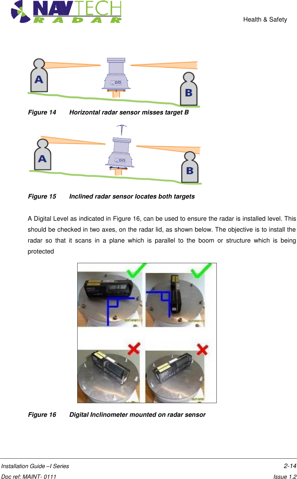
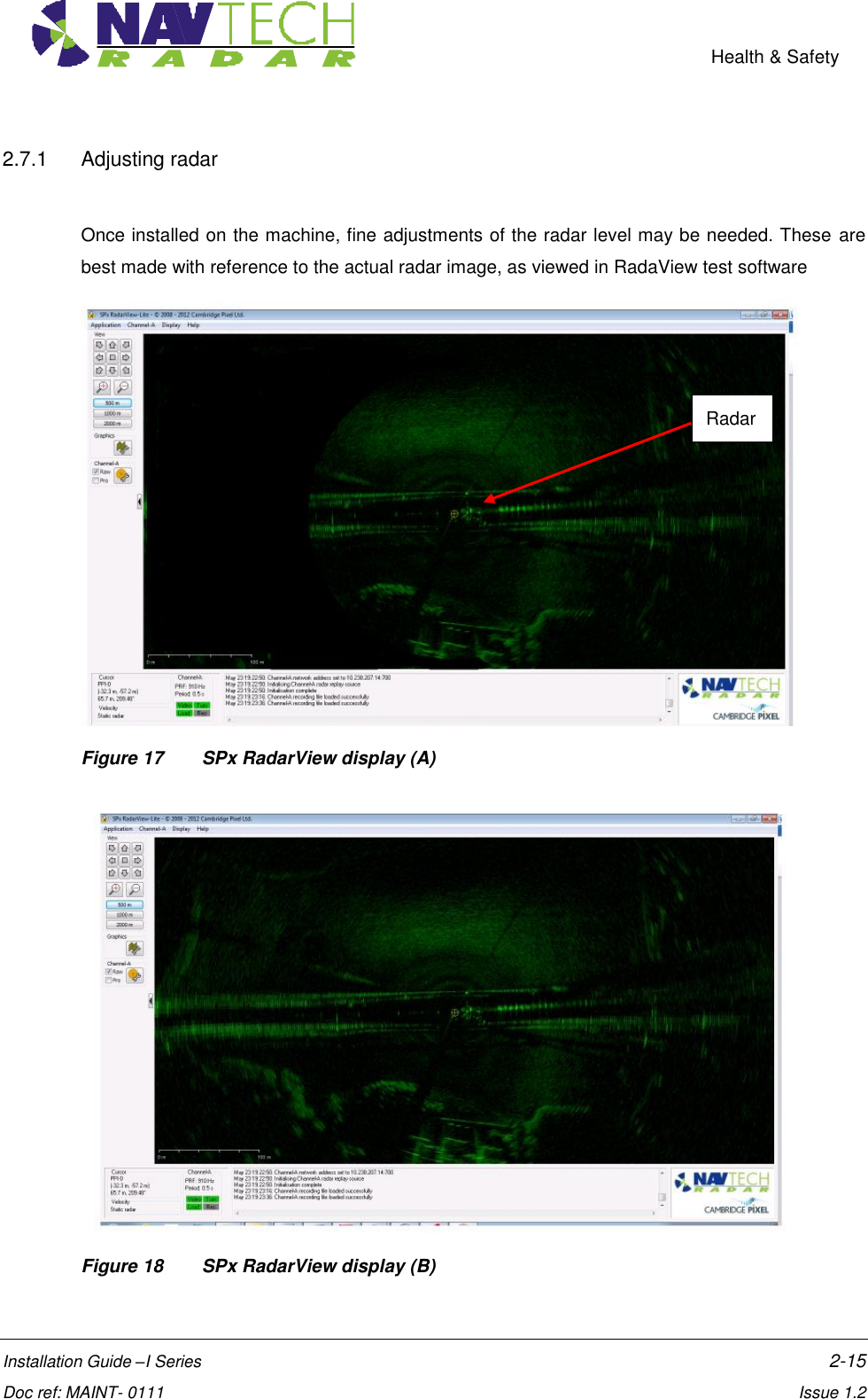
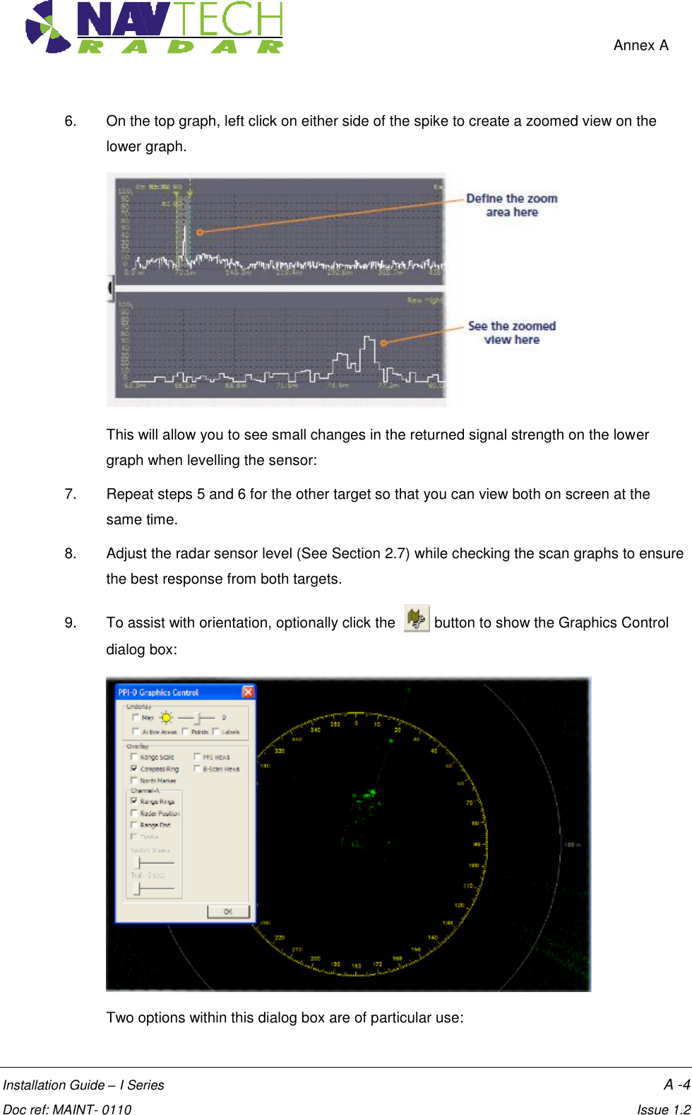
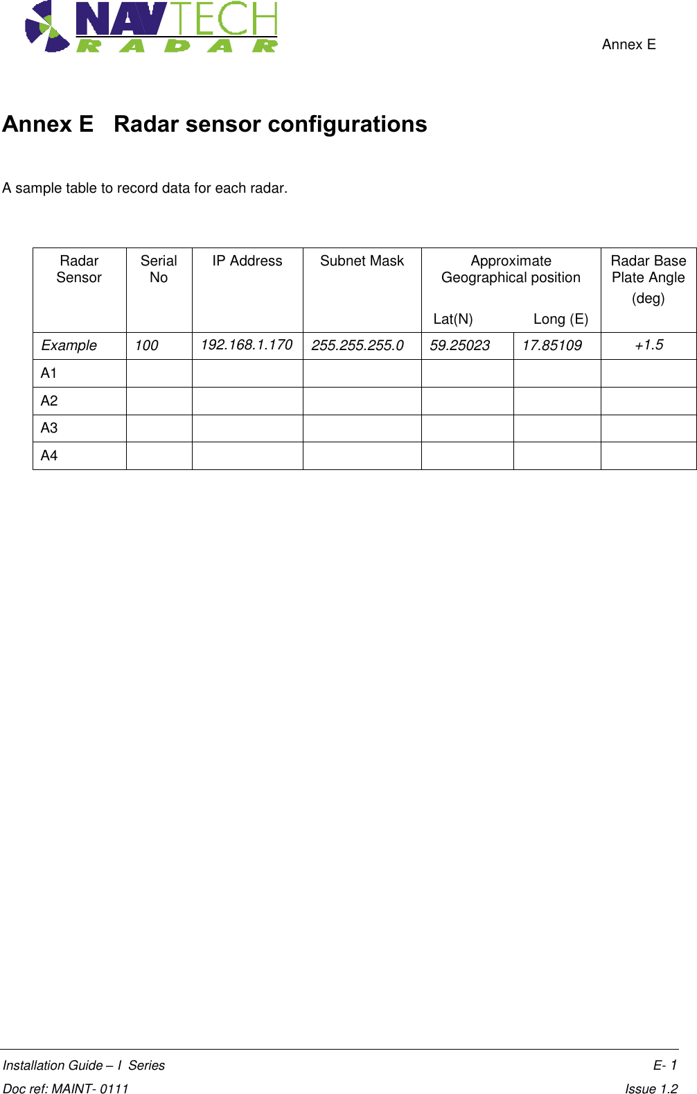
![Health & Safety Installation Guide –I Series 2-16 Doc ref: MAINT- 0111 Issue 1.2 Using the RadarView application to view the radar data (see Annex A), you are aiming to have an equal amount of data either side of the radar. 1. If there is more radar data one side than the other, as shown in Figure 17, change the angle of the radar until you have an equal amount of data either side of the radar, as shown in Figure 18. Radar targets can be used as the test object. 2. If there is not enough radar image to view from objects/structures already within the radar line of sight, test targets can be used instead. Adjust the radar tilt of the radar on the threaded studs, to maximise the signal level on the 2 targets are determined from the RadarVew software (See Annex A for detailed instruction). Figure 19 Radar view to locate target 2.8 Securing the radar 1. Secure the radar on the mounting bracket, or post plate. To do this: lock off the two lower nuts on each stud by tightening one against the other. (This is to ensure that, if the radar is removed, the tilt angle is not changed) 2. Record the tilt angle from the digital inclinometer. See Annex E for a sample table. 2.9 Confirming sensor coverage 1. Install and configure the witness software as described in [2]. 2. Enter basic detection areas into the witness interface. (See [2]). 3. Where possible, place test objects into the radar detection zone. Monitor these on the interface and confirm that detection alarms are raised](https://usermanual.wiki/Navtech-Radar/TS350X-001.User-Guide-2/User-Guide-1970752-Page-23.png)