NEC FC-N21S Computer FC-NOTE Series User Manual FC N21S
NEC Corporation Computer FC-NOTE Series FC N21S
UserManual.wiki
>
NEC
>
FC-N21S User Manual
>
User Manual 2
Contents
1.
User Manual 1
2.
User Manual 2
3.
User Manual 3
User Manual 2
Navigation menu
Upload a User Manual
Namespaces
Wiki Guide
HTML
PDF
Info
Views
User Manual
Discussion / Help
Navigation
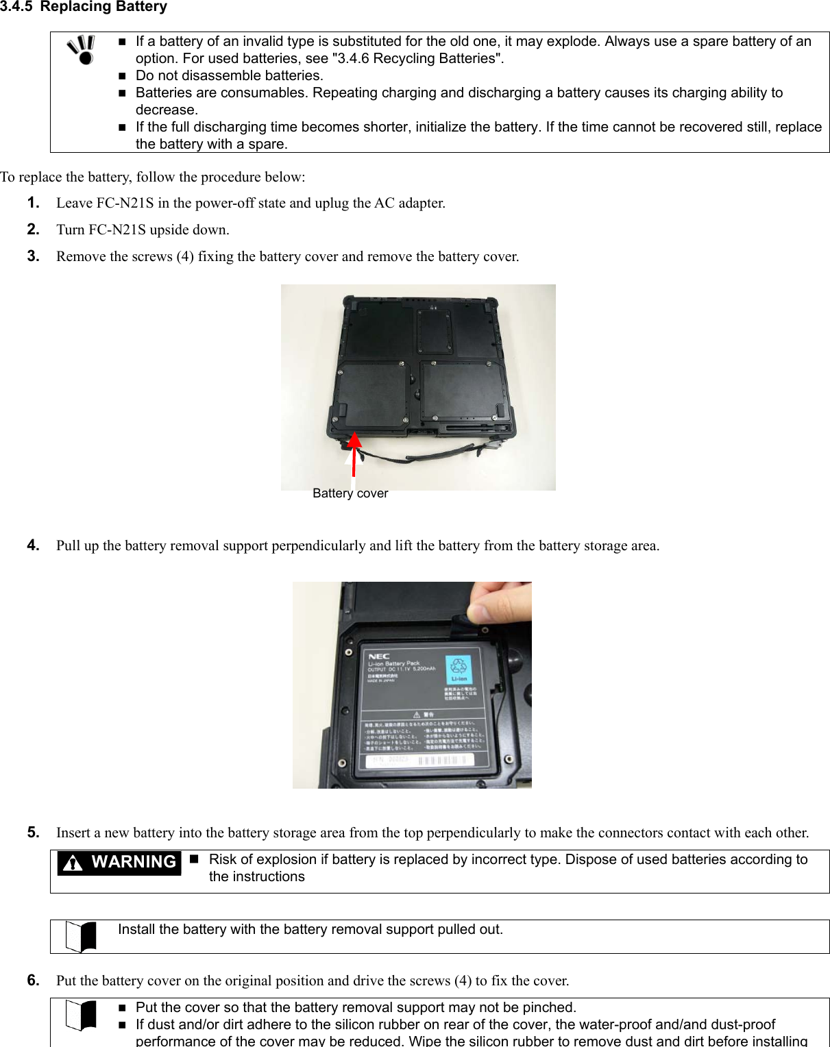
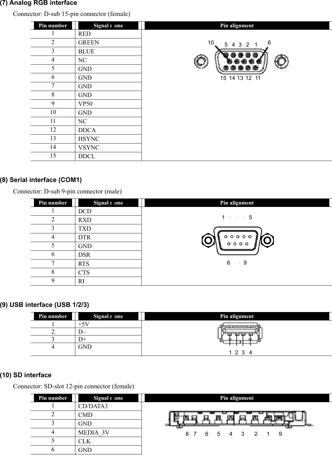
![3.4.2 Charging Battery WARNING Risk of explosion if battery is replaced by incorrect type. Dispose of used batteries according to the instructions The battery is not charged any more if its temperature exceeds 60ºC. In battery charging status, remove the AC adapter only after the battery is fully charged. It the AC adapter is removed on the way, the battery cannot be charged fully. To charge the battery, first connect the AC adapter to FC-N21S and a power outlet. The battery charge LED on FC-N21S illuminates in orange to indicate that the battery is now being charged. It is recommended to turn off the power of FC-N21S while the battery is charged. After the battery is fully charged, the battery charge LED goes off. It takes about three hours to charge the battery fully. Just after the battery is fully charged, do not take the procedure of removing the AC adapter from FC-N21S and reconnecting it to start charging again. Failure to follow this instruction may cause the battery to be damaged. If an error occurs in the battery, the battery charge LED blinks. The temperature may rise extraordinary or the battery may be defected. Move FC-N21S to a place of good ventilation or stop using FC-N21S to lower its temperature. If the battery charge LED blinks still, remove the AC adapter from FC-N21S and stop using it. Contact your service representative. 3.4.3 Initializing Battery Initializing the battery is intended to recover its performance decreased temporarily. The initialization process consists of full charge, full discharge and full recharge of the battery in the order. It takes about 4.5 hours for the initialization. Initialize the battery in the following cases: FC-N21S can be operated by the battery for a shorter period than before. Repeating battery charging in other than the full discharge state may cause the full-chargeable level of the battery to be reduced, which then may shorten the driving period. This is called battery’s memory effect. Because the battery is just purchased or has not been used for a long period, its performance is reduced temporarily. The indicator of the remaining battery level shows some error. 1. Turn off the power of FC-N21S if operated. 2. If the batter pack is not installed, install the battery pack in FC-N21S. 3. If the AC adapter is not connected to FC-N21S yet, connect the AC adapter to FC-N21S and the power cord to an AC outlet. 4. If the battery charge lamp blinks, remove the battery pack from FC-N21S once and install it again. 5. Charge the battery fully (until the battery charge lamp disappears). 6. Turn on the power of FC-N21S. If the NEC logo screen appears, press F2 to display the BIOS Setup Menu. 7. Unplug the power cord from the AC outlet and remove the AC adapter from FC-N21S. 8. Select [Battery refresh] in the Power Management menu and press Enter. 9. If message "Refresh your battery now?" select [Yes] and press Enter. The following dialog box appears. Refresh battery program Press Y to start refresh, N to exit <ESC> to shutdown system 10. Press Y to start battery initialization. Whil th b tt i i iti li d l th LCD di l l d](https://usermanual.wiki/NEC/FC-N21S.User-Manual-2/User-Guide-865916-Page-1.png)
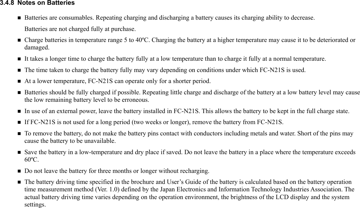
![3.4.4 Checking Remaining Battery Level To activate the screen, wait for several minutes before the AC adapter is disconnected from FC-N21S. "Total time remaining" may be different from the actual operation time depending on the operation status of FC-N21S. For Windows XP 1. Click [Start] → [Control Panel] → [Performance and Maintenance] → [Power Options]. Then the [Power Options Properties] dialog box appears. 2. Select the [Power Meter] tab and check [Show details for each battery.]. For Windows XP, the dialog box shown below appears to allow you to check the remaining battery level.](https://usermanual.wiki/NEC/FC-N21S.User-Manual-2/User-Guide-865916-Page-2.png)
![3.4.6 Recycling Batteries A lithium ion battery is used for FC-N21S. Lithium ion batteries are valuable resources being recyclable. To protect valuable resources, do not dispose batteries becoming unnecessary but bring them to any of the following carry-on centers: * For details of the carry-on centers, see the NEC environmental web page below: URL:http://www.nec.co.jp/eco/ja/products/3r/indes_denchi.html Notes on handling batteries in recycling Insulate connectors with tape. Do not peel off coating. Do not disassemble batteries. To keep batteries, enter them in a rugged case and put the lid on the case. Keep batteries so that they may not get wet with rain. Do not leave batteries in the sun. 3.4.7 Actions Taken for Low Battery Charge Level (1) Decreasing in remaining battery level during battery driving If the battery power remains only a little, the power LED on FC-N21S illuminates in yellow or orange to inform that the battery should be charged If so, perform either of the following operations depending on situations: Possible supply of AC power through AC outlet Connect the AC adapter to FC-N21S to supply AC power through an AC outlet. Then the battery charge LED illuminates in orange and battery charge is started. Impossible supply of AC power through AC outlet Abort applications being operated and turn off the power. In the lower battery charge level, do not access to a card such as an SD card if used. Accessing to the card may fail because the time taken for the accessing can be longer than the full discharging time. If the battery is discharged fully before data storage, the data is lost. (2) Setting operation of FC-N21S at low battery level The operation and state of FC-N21S in a low or no battery charge level can be defined. For Windows XP 1. Click [Start] → [Control Panel] → [Performance and Maintenance] → [Power Options]. Then the [Power Options Properties] dialog box appears. 2. Click the [Alarms] tab and change the alarm options. To define operation of FC-N21S in a low battery charge level, logon to it with a user account having the administrator authority.](https://usermanual.wiki/NEC/FC-N21S.User-Manual-2/User-Guide-865916-Page-4.png)
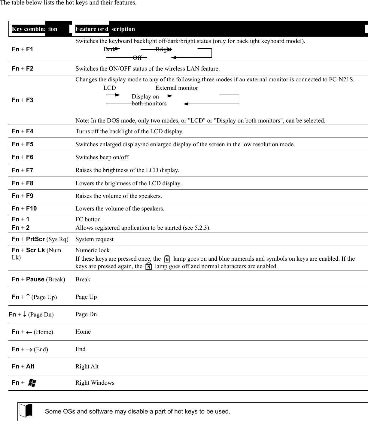
![3.5 TABLET BUTTONS The following describes the names and features of the tablet buttons. (1) [Tb] button (2) Tablet button 1 (3) Tablet button 2 (4) Tablet button 3 (5) Tablet button 4 (6) Tablet button 5 (7) Label pasting area (7(1) (2) (3) (4) (5) (6) ) (1) Operations at depression of buttons Button Operation (defined at shipment) Tablet button 1 Ctrl + Alt + Del Tablet button 2 Rotates the Windows screen. Tablet button 3 Enter Tablet button 4 Increases brightness of the LCD screen. Tablet button 5 Decreases brightness of the LCD screen. [Tb] + Tablet button 1 Esc [Tb] + Tablet button 2 Tab [Tb] + Tablet button 3 Starts the screen keyboard. [Tb] + Tablet button 4 Moves the cursor upward. [Tb] + Tablet button 5 Moves the cursor downward. (2) Label pasting area When key assignment is changed, you can paste a label showing the new key assignment on the area. The possible label size is as follows. Prepare the label if required. Size: 60 mm3 mm (3) Changing key assignment See "Chapter 4 Setting BIOS" for how to change the key assignment.](https://usermanual.wiki/NEC/FC-N21S.User-Manual-2/User-Guide-865916-Page-6.png)
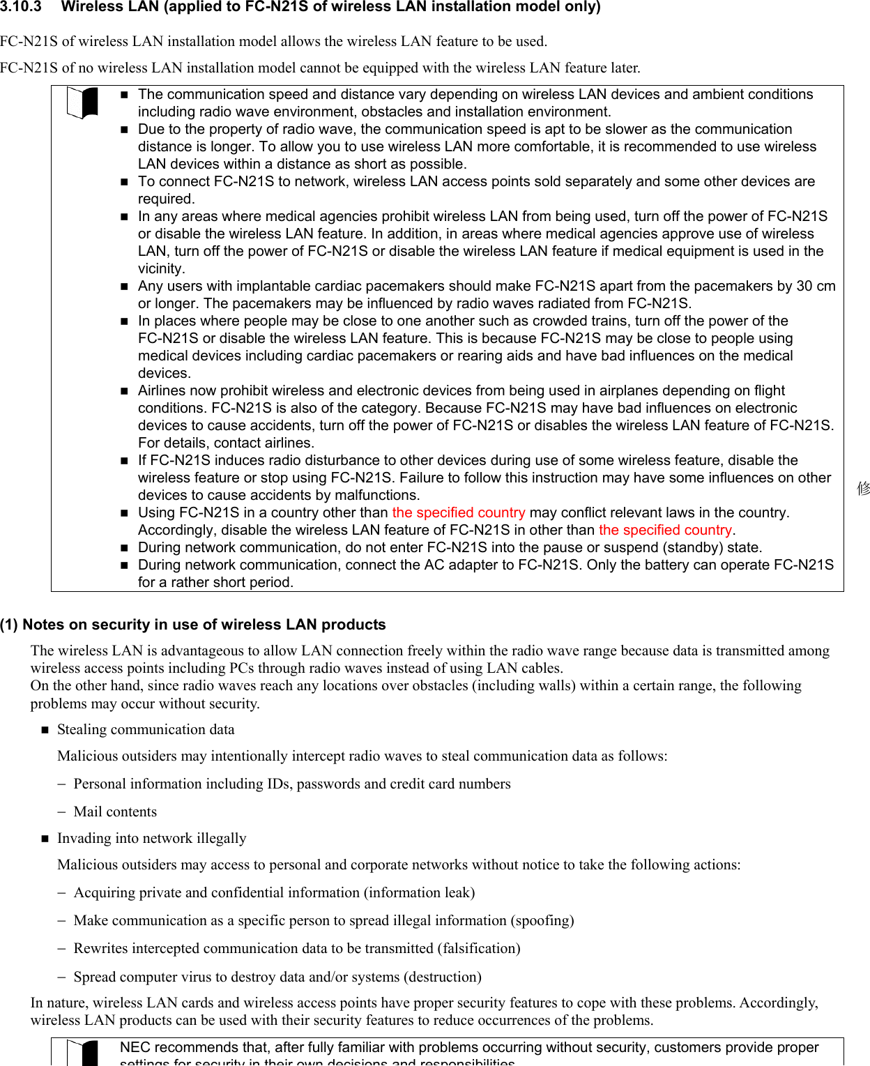
![3.6 KEYBOARD 3.6.1 English Keyboard If English OS is selected on the selection menu, the English keyboard is installed. 3.6.1.1 Uses of Hot Key [FN] Combining Fn with another key allows various operations on FC-N21S to be done easily. These are called hot key features. Some icons indicating the features resulting from combinations of respective keys with Fn are printed on the keys with the same color as Fn.](https://usermanual.wiki/NEC/FC-N21S.User-Manual-2/User-Guide-865916-Page-7.png)
![3.6.1.2 Typing the Euro Symbol To type the Euro symbol "€", follow these steps to change the key layout of the keyboard. 3. Click [Start] → [Control Panel]. 4. Click [Date, Time, Language, and Regional Options] and [Regional and Language Options]. 5. Click [Details…] in [Text services and input languages] of the [Language] tab. Note: If you find the desired keyboard layout in the list of installed services, go to step 8. Click [Add] in [Installed services]. 6. Select [English (United States)] from [Input language:]. 7. Select [United States-International] from If [Keyboard layout/IME:]. 8. Click [OK]. 9. Select [English (United States) – United States-International] from [Default input language]. 10. Click [OK]. 11. Click [OK]. After restarting Windows, the Euro symbol "€" can be obtained by pressing Ctrl + Alt + 5.](https://usermanual.wiki/NEC/FC-N21S.User-Manual-2/User-Guide-865916-Page-9.png)
![3.7 TOUCH PAD Do not make a sharp object such as a ballpoint pen contact with the touch pad. Failure to follow this instruction may cause the surface of the touch panel to be damaged. To maintain the optimum performance of the touch pad, keep your fingers and the pad clean and dry. Make a finger contact with the pad lightly without excess force. The touch pad is a pointing device on which you can control the position of the pointer and select a proper button to communicate with FC-N21S. The touch pad is composed of a rectangle pad and two buttons. Moving a finger on the pad allows the pointer on the screen (also called the cursor) to be moved. If the finger reaches to an end of the pad, let the finger away from the pad and put it at the opposite end. Then you can continue to move the pointer. The table below describes general terms with which you should be familiar on the touch pad. Term Operation Point Move a finger on the pad to make the cursor reach to the intended target on the screen. Click Press and release the left button, or hit the pad lightly. Double-click Press and release the left button twice fast, or hit the pad twice fast. Drag & drop With the left button remaining pressed, move the finger until the cursor reaches to the intended point (drag). After dragging to the intended point in the selected range, release the button (drop). The object is dropped at the new point. –Or– Tap the pad twice with a finger lightly and leave the finger contact with the pad at the second tapping. Then move the finger on the pad to drag the selected object to the intended point. Releasing the finger from the pad, the selected object is dropped at the new point. Scroll The scroll means that the display area is altered in the longitudinal or transverse direction within the working area on the screen. To alter the display area in the longitudinal direction, put a finger at the right end of the pad and slide it along the end. To alter the display area in the transverse direction, put a finger at the bottom of the pad and slide it along the bottom. The feature can be used only when the touch pad driver attached to FC-N21S is installed. Some applications may disable the feature to be operated. Note on table above: If the left and right buttons on the touch pad are interchanged, tapping the touch panel cannot substitute for pressing the left button. 3.7.1 Setting Touch Pad Settings of the touch pad can be changed depending on user needs. For example, left-handed users can interchange the features of the left and right buttons to use the left and right buttons as the right and left buttons in the normal state, respectively. In addition, the size and speed of the pointer on the screen may be changed. For Windows XP 1. Click [Start] → [Control Panel] → [Printers and Other Hardware] → [Mouse]. Then the [Mouse Properties] dialog box appears. 2. Selecting the [Buttons], [Pointers] and/or [Pointer Options] tabs, you can set operations of the touch pad appropriately. The features of the touch pad can be enabled/disabled by changing some BIOS settings.](https://usermanual.wiki/NEC/FC-N21S.User-Manual-2/User-Guide-865916-Page-10.png)
![3.8 TOUCH PANEL Use the attached touch pen or a finger to contact with the touch panel so that the panel may not be hurt. Do not make a sharp object such as a ballpoint pen or a pencil contact with the touch panel. Failure to follow this instruction may cause the touch panel to be damaged. If the surface of the touch panel is dirt, wipe the surface with a dry and soft cloth such as a glass wiping cloth. If manipulating the touch panel with dust adhering on the surface may cause the surface to be hurt. Neither put your hands on the surface of the touch panel nor push the surrounding of the touch panel hard. The pointer (cursor) may not be operated normally or moved to an end of the screen. While the touch panel is manipulated, do not put your hands on the keyboard. Failure to follow this instruction may cause key entries to occur. The touch panel is a pressure-sensitive device on which you can control the position of the pointer and select a proper button to communicate with FC-N21S. The touch pen can be stored on the base of FC-N21S (see "(2) Outside sections" in Chapter 1). To use the touch panel, put the touch pen or your index finger on the touch panel. If you slide the pen or the finger tip on the panel, the pointer (cursor) on the screen is moved in the same direction as the pen or finger. The table below describes general terms with which you should be familiar on the touch panel. If the left and right buttons on the touch pad are interchanged, tapping the touch panel cannot substitute for pressing the left button. Term Operation Point Slide the pen or finger on the touch panel until the cursor reaches to the intended target on the screen. Click Tap a point on the touch panel lightly. Double-click Tap the touch panel twice fast. Drag & drop Press the touch panel with the pen or finger lightly and slide the pen or finger to the intended point (drag). After dragging to the intended point in the selected range, release the pen or finger (drop). The object is dropped at the new point. 3.8.1 Setting Touch Panel (1) Setting features You can change the size and speed of the pointer on the screen. For Windows XP 1. Click [Start] → [Control Panel] → [Printers and Other Hardware] → [Mouse]. Then the [Mouse Properties] dialog box appears. 2. Selecting the [Buttons], [Pointers] and/or [Pointer Options] tabs, you can set operations of the touch pad appropriately. Settings on the touch pad are also applied to the touch panel. The touch panel cannot be independent of the touch pad. (2) Compensating position The position of pointer must be compensated in the following cases: Changing the resolution of the screen is changed, or The pointer is not moved properly to the point with which you make the touch pen contact. Compensate the point of the pointer in the following procedure: 1. Click [Start] → [All Programs] → [Gunze TPDD] → [Calibrate].](https://usermanual.wiki/NEC/FC-N21S.User-Manual-2/User-Guide-865916-Page-11.png)
![3.9 DISPLAY FEATURE The display features of FC-N21S are characterized as follows: 12.1-in. TFT (Thin-Film Transistor) color LCD display of resolution 1024×768 XGA (Extended Video Graphics Array) Concurrent display of both LCD display and external monitor Some OSs may limit display modes. 3.9.1 Display Resolution The default resolution and the default number of colors are set at shipment of FC-N21S. For display of a higher resolution, FC-N21S can connect with an external monitor supporting the higher resolution. The table below shows the display modes available to FC-N21S. Display mode LCD display only Resolution Number of colors 800×600 16 bits 32 bits 1024×768 16 bits 32 bits * FC-N21S allows external monitors can have resolutions in the range from 640×480 to 1920×1200 and the number of colors of 8, 16 and/or 32 bits. However, the used external monitor limits available resolutions and the available number of colors. Notes on color: 8 bits = 256 colors 16 bits = High Color or 65,536 (64 K) colors 32 bits = True Color 16,770,000 (16 M) colors (16.77 million color display is accomplished by the dithering feature of the graphic accelerator.) Some OSs may limit display modes. 3.9.2 Adjusting Screen Display To change the resolution or the number of colors of the screen, follow the procedure below: 1. Perform the following operation. For Windows XP: Click [Start] → [Control Panel] → [Appearance and Themes] → [Display]. Then the [Display Properties] dialog box appears. 2. Select the [Settings] tab to set the resolution and/or the number of colors of the screen. To enable the virtual screen feature, follow the procedure below: On the screen displayed by selecting the [Settings] tab, click the [Advanced] button. Click the [Monitor] tab. Click [Hide modes that this monitor cannot display] to uncheck it. Click [OK]. 3.9.3 Connecting External Monitor To get a wide display screen of a higher resolution, an external monitor can be connected to FC-N21S through an external monitor connector. Follow the procedure below. 1. Confirm that the power of FC-N21S is OFF. 2. Connect a proper monitor cable to the connector on the external monitor.](https://usermanual.wiki/NEC/FC-N21S.User-Manual-2/User-Guide-865916-Page-12.png)
![3.10 COMMUNICATION FEATURE 3.10.1 Modem (1) Connecting FC-N21S with phone line FC-N21S can only connect with a phone line of 2-wire type. Before connecting FC-N21S with a phone line, check the type of the phone line. The diameter of the phone line must be a minimum of 26AWG. The built-in fax modem is designed to be applicable to the subscriber phone line. Connecting the modem to other than the subscriber phone line may cause the modem to operate improperly or the modem and/or FC-N21S to be damaged. If a modular cable is connected to the RJ-11 connector (phone line modular connector) on FC-N21S, neither pull the modular cable nor move FC-N21S. Failure to follow this instruction may cause the RJ-11 connector to be damaged. Connecting a modular cable to the LAN connector may cause a fault to occur. Check the connector to be connected securely before the connection. 1. Turn off the power of FC-N21S if operated. 2. Remove a modular cable of a phone from the mating modular jack. 3. Insert one end of the modular cable to the RJ-11 connector (modular connector for phone line) on FC-N21S to the depth securely. 4. Insert the other end of the modular cable to a modular jack on a near wall to the depth securely. (2) Setting modem 1. Perform the following operation. For Windows XP: Click [Start] → [Control Panel] → [Printers and Other Hardware] → [Phone and Modem Options]. Then the [Phone and Modem Options] dialog box appears. 2. Provide setting for [Edit Location] in the [Dialing Rules] tab. Confirm that "Japan" is selected in field [Country/Region] if FC-S21S is used in Japan. 3. After completing the setting, click [OK]. Then click [OK] again. 4. Close the [Printers and Other Hardware] dialog box. 5. Provide proper setting on the dialup connection depending on used applications (including Internet Explorer and Hyper Terminal). The built-in modem has the feature of specifying a country other than Japan. Using the built-in modem of another country mode in Japan fringes the Telecommunication Service Law (Technical Standard). Before using the modem in Japan, confirm that the country/region mode is set to Japan. 修](https://usermanual.wiki/NEC/FC-N21S.User-Manual-2/User-Guide-865916-Page-13.png)
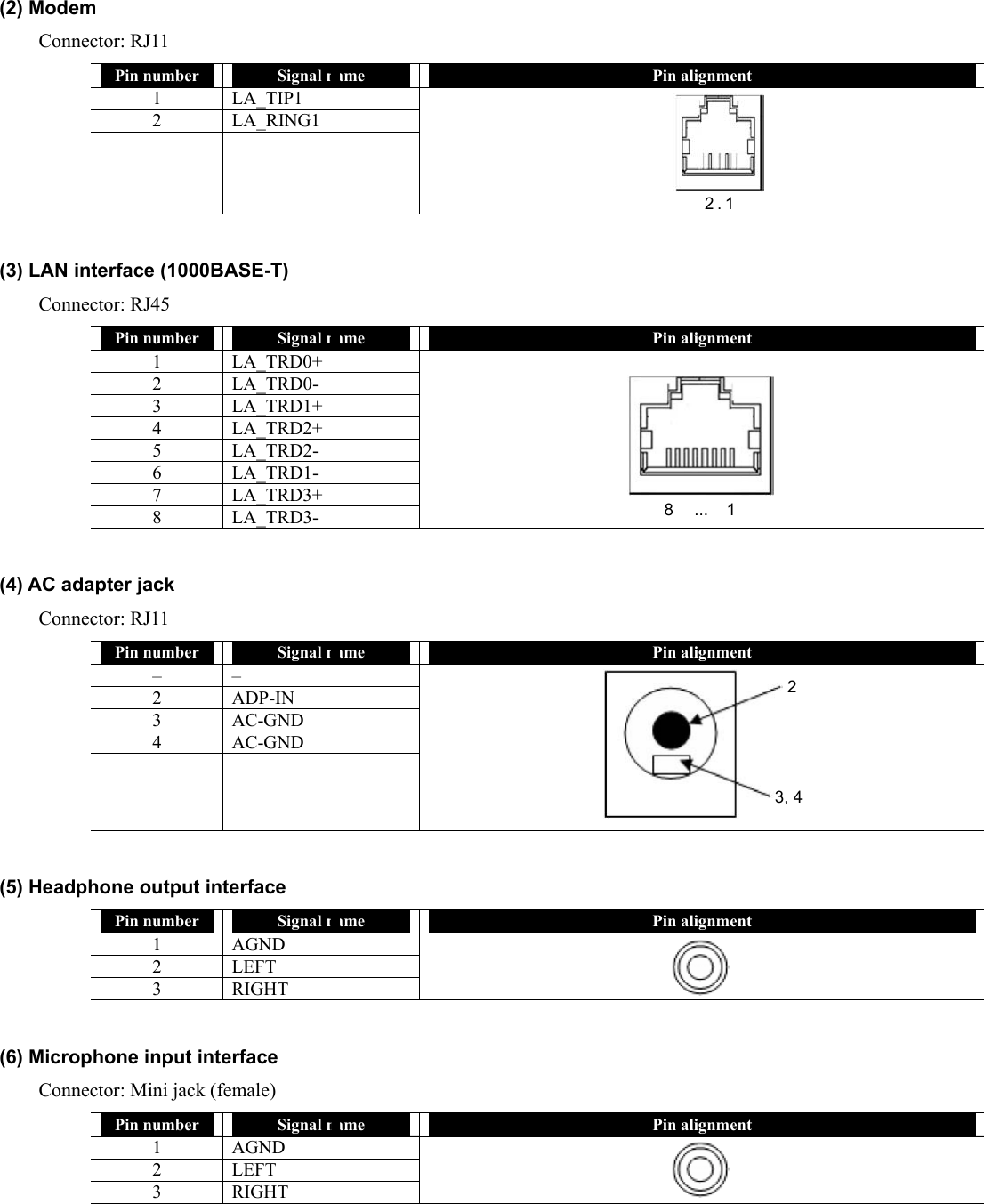
![3.10.2 LAN While FC-N21S operates, do not remove the LAN cable from the hub. If removed, the network connection will be cut out. If the LAN cable is removed during network connection, immediate re-connection may be able to recover the operation. If not, restart OS. During network communication through LAN, connect the AC adapter to FC-N21S. Only the battery can operate FC-N21S for a rather short period. The suspend (standby) or pause state disables the network feature. During network communication, do not enter FC-N21S into the suspend (standby) or pause state. To run an application using network, enter FC-N21S into the suspend (standby) or pause state after asking a system administrator to confirm that the application may be used in suspend (standby) or pause state. Some applications may cause data to be lost when FC-N21S is recovered from the suspend (standby) or pause state. The built-in 1000BASE-T LAN module allows FC-N21S to connect with network. The module supports the data transfer rate of up to 1000 Mbps. (1) Connecting FC-N21S to network To connect FC-N21S to network, a LAN cable sold separately is required. 1. Insert one end of a LAN cable to the RJ-45 connector (LAN connector) on FC-N21S to the depth securely. 2. Insert the other end of the LAN cable to the network connector to the depth securely. (2) Setting LAN Perform the following operation. For Windows XP: 1. Click [Start] → [Control Panel] → [Network and Internet Connection] → [Network Connections]. 2. Double-click [Local Area Connection] to display the [Local Area Connection Status] dialog box. Click [Properties]. 3. The [Local Area Connection Properties] dialog box appears. Provide settings appropriate for the connected network. If you do not know necessary components, contact a system or network administrator. (3) Remote power-on feature The remote power-on feature of FC-N21S supports the recover of FC-N21S from the suspend (standby), pause or power-off state. To use the remote power-on feature by the LAN built in FC-N21S, the following settings are required. (1) Settings associated with BIOS Setup Menu (common to OSs) 1. Power management - Wake On LAN/PME: Enabled 2. Security - Network Boot Setting - Keyboard/mouse Lock: Disabled * Without the setting, keyboard and mouse operations are disabled at remote power-on. (2) Settings associated with network adaptor Depending on used OSs, the following settings are required. 1. For the advanced network configuration, click [Control Panel] → [Network and Internet Connections] → [Network Connections], right-click [Local Area Connection], and click [Properties] → [Configure...]. 2. For the power management settings, click [Control Panel] → [Network and Internet Connections] → [Network Connections], right-click [Local Area Connection], and click [Properties] → [Configure...]. UdOSS tti bOS](https://usermanual.wiki/NEC/FC-N21S.User-Manual-2/User-Guide-865916-Page-14.png)
![(2) Security enabled by FC-N21S The wireless LAN installed in FC-N21S has the following security features. To provide the following security, used access points should be applicable to the settings. These settings are only intended to reduce security risks as much as possible but do not assure complete safety to avoid security risks. 1. Preventing interception Setting an encryption key by using the WEP feature allows wireless LAN data among communication devices using the specific encryption key to be encrypted. However, encryption keys may possibly be known by outsiders or decrypted by decryption technology. Accordingly, it is recommended to change encryption keys periodically. See "3.10.3 (5) Setting WEP feature" for setting WEP features. 2. Preventing illegal accesses Setting specific SSIDs (network names) for both access points and communication devices can avoid connections from communication devices without the same SSIDs. However, SSIDs can be known by using devices which have the feature of detecting SSIDs automatically. To avoid this, SSID hiding must be set on access points not to notify them. Registering MAC addresses of connected devices in each access point disables devices not registered to connect to the access point (MAC address filtering). See "3.10.3 (4) Setting SSID feature" for setting SSIDs. (3) Setting wireless LAN Perform the following operations. For Windows XP: 1. Click [Start] → [All Programs] → [Intel PROSet Wireless] → [Intel PROSet Wireless]. 2. Press Fn + F2 to enable the wireless feature. If you use wireless LAN for the first time, click [Enable Intel PROSet/Wireless] on the [Intel® PROSet/Wireless] dialog box. 3. Connectable wireless networks appears. Select a desired network and click [Connect]. Provide settings appropriate for the selected network. (4) Setting SSID feature Perform the following operations. For Windows XP: 1. Select a connectable wireless network in the [Intel® PROSet/Wireless] dialog box and click [Connect]. 2. Enter proper names in fields [Profile Name] and [Wireless Network Name (SSID)].](https://usermanual.wiki/NEC/FC-N21S.User-Manual-2/User-Guide-865916-Page-16.png)
![(5) Setting WEP feature Perform the following operation. For Windows XP: 1. In the [Configure Wireless Settings] dialog box, select [WEP] in the [Data Encryption] field. Then provide settings appropriate for the connected network. 3.10.4 Serial Port While the power of FC-N21S is ON, do not connect or disconnect the serial cable. Failure to follow the instruction may cause FC-N21S to operate improperly. FC-N21S has a serial port connecting with a serial device including a serial mouse or modem. To connect a serial device to FC-N21S, follow the procedure below: 1. Confirm that [Enabled] is selected in item "Serial Port A:" in BIOS setting (see "Chapter 4 Setting BIOS" for details). 2. Confirm that the power of FC-N21S is off. 3. Insert the cable of a serial device to the serial port on FC-N21S. Some OSs may limit serial features. 4. Turn on the power of FC-N21S. FC-N21S cannot connect with a portable modem getting power through the serial port. Use the built-in battery or a modem using external AC power.](https://usermanual.wiki/NEC/FC-N21S.User-Manual-2/User-Guide-865916-Page-17.png)
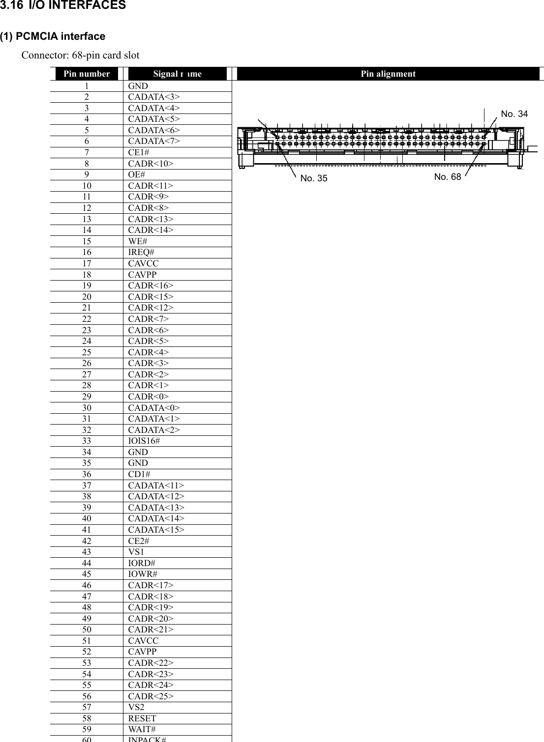
![3.10.5 USB (USB 2.0) USB is the prefix indicating the Universal Serial Bus. The USB has the defined shapes of connectors and allows a PC to connect with up to 127 devices. In addition, the USB provides the plug & play feature to allow the connector of a device to be connected/disconnected without the power of FC-N21S turned off. Available USB devices mainly include pointing device, printers, digital cameras, mobile phones and PHSs. Some USB devices require driver installations and/or switch settings before or after they are connected to FC-N21S. Refer to the User’s Guides of USB devices to be connected to FC-N21S before using them. After disconnecting a USB device from FC-N21S, wait for three seconds or longer before the device is connected again. If the connector of a USB device is connected to a USB connector on FC-N21S quickly or obliquely, FC-N21S may not be able to read signals properly to recognize it as an unknown device. If so, remove the connector from the USB connector once and reconnect it again. Do not connect or remove a USB device to/from FC-N21S in the suspend (standby) state, transition to the suspend (standby) state, recovery from the suspend (standby) state, the pause state, transition to the pause state, or recovery from the pause state. If FC-N21S connects with one or more USB devices, it may not be able to enter into the suspend (standby) state. Before FC-N21S can be entered into the suspend (standby) state, the USB devices must be removed. Some OSs may limit the features of USB devices. [Specification] Standard: USB2.0 Voltage: 5 VDC Current: 0.5 A/port (1) Connecting USB devices to FC-N21S FC-N21S has three USB ports intended to connect with USB2.0 devices on the left side. To connect a USB device to FC-N21S, insert the plug of the USB cable to a USB connector on FC-N21S. When a USB device is connected to FC-N21S, note the orientation of the plug to be inserted to a USB connector. (2) Removing USB devices from FC-N21S Some USB devices may cause the icon for removing or taking out hardware to appear on the task tray at the lower right corner of the screen after the connection. 1. Double-click the icon to display the [Safely Remove Hardware] or [Remove Hardware] dialog box. 2. Select a device to be removed in the dialog box and click [Stop]. 3. "Stop a Hardware device" is indicated. Select the device to be removed and click [OK]. 4. Click [Close] to close the [Safely Remove Hardware] or [Remove Hardware] dialog box. Unless a USB device is removed appropriately, FC-N21S may operate improperly. Remove a USB device in the correct procedure. (3) Connect/disconnect-proof enhanced connector USB connector (1) is the connect/disconnect-proof enhanced connector enduring 10,000 combinations of connections and disconnections.](https://usermanual.wiki/NEC/FC-N21S.User-Manual-2/User-Guide-865916-Page-18.png)
![3.11 PC CARD FC-N21S has a single PC card slot to which a card of type I or II can be inserted. 3.11.1 Supporting CardBus The PC card slot on FC-21S conforms to the CardBus specification. The CardBus technology is intended for PC cards of 32-bit version. This can accomplish the data transfer rate of up to 133 Mbps at 33 MHz. SCSI host bus, graphics video and high-speed network cards are available to CardBus. 3.11.2 Installing PC Card in FC-N21S Some PC cards require certain system resources to be added. When such PC cards are used, other system resources may have to be released. The front and rear sides of a PC card are defined and thus the card must be inserted to the mating slot in the defined orientation. Inserting a PC card to the mating slot in the wrong orientation forcibly may cause the connector and/or slot to be damaged. Some PC cards can be inserted to or removed from FC-N21S without turning off the power. However, any PC card cannot be inserted to or removed from FC-N21S in the suspend (standby) state. If FC-N21S is in the suspend (standby) or pause state, do not install or remove a PC card in or from FC-N21S. Changing the device configuration of FC-N21S may cause data to be lost. Do not install or remove a PC card in or from FC-N21S while one or more applications operate. Leave the eject button stored in other than removal of the PC card. Failure to follow this instruction may cause the card and/or slot to be defected. 1. Find the PC card slot on the right side of FC-N21S. 2. Insert a PC card into the slot until the eject button is popped up. 3. If the new card is inserted, FC-N21S detects the card and installs proper driver. Follow the directions on the screen to complete the procedure. 3.11.3 Removing PC Card from FC-N21S Some PC cards may cause icon [Removing or Taking Out Hardware] to appear on the task tray at the lower right corner of the screen at the connection. 1. Double-click the icon to display the [Safely Remove Hardware] or [Remove Hardware] dialog box. 2. Select a device to be removed in the dialog box and click [Stop]. 3. "Stop a Hardware device" is indicated. Select the device to be removed and click [OK]. 4. Click [Close] to close the [Safely Remove Hardware] or [Remove Hardware] dialog box. 5. If you press the eject button, the card is popped up a little. 6. Pull out the PC card from the slot. Unless the PC card is removed appropriately, FC-N21S may operate improperly. Remove the PC card in the correct procedure.](https://usermanual.wiki/NEC/FC-N21S.User-Manual-2/User-Guide-865916-Page-19.png)
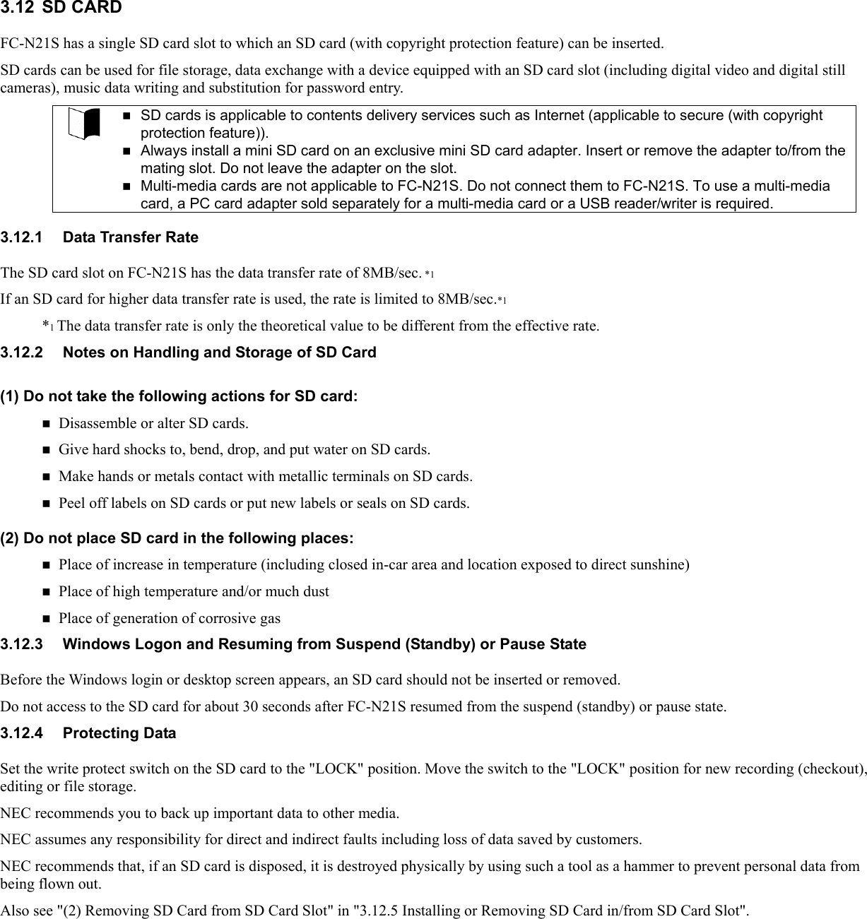
![3.12.5 Installing or Removing SD Card in/from SD Card Slot (1) Inserting SD Card into SD Card Slot When an SD card is inserted to the SD card slot, note the orientation of the card. Inserting an SD card in invalid orientation may cause a fault to occur. 1. Open the connector cover. 2. Insert an SD card securely into the SD card slot from the side of edge defect with its front surface facing upward. (2) Removing SD Card from SD Card Slot Before the SD card can be removed, the card must always be halted. Do not remove the SD card from the SD card slot in any of the following cases. Failure to follow this instruction may cause important data to be damaged or the SD card to be accessed improperly at the next installation. – The SD card opens one or more files (first close the files before removing the SD card), – The SD card reads of writes data from or to FC-N21S, or – Just after the SD card performs operation such as writing (the SD card may access to FC-N21S intermittently). – FC-N21S is in the suspend (standby) or pause state, 1. Halt the SD card. 1. Double-click the [Safely Remove Hardware] icon on the task tray at the lower right corner of the screen 2. Click [Secure Digital Storage Device] and [Stop]. 3. Click [Secure Digital Storage Device] and [OK]. The procedure is not required if the SD card is removed in the power-off state. 2. Pushing the SD card allows it to be popped up a little. Then pull out the card. Before the SD card can be stored, it should be saved in a case.](https://usermanual.wiki/NEC/FC-N21S.User-Manual-2/User-Guide-865916-Page-21.png)
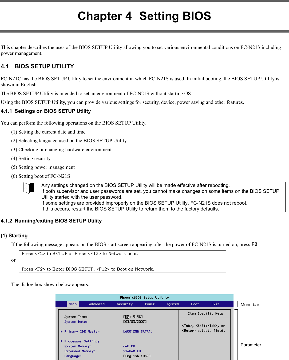
![(2) Exiting 1. Press F10. 2. The [Setup Confirmation] dialog box appears. 3. Select [Yes] and press Enter. The setting values are saved and the BIOS SETUP Utility is exited. Selecting [Exit] on the menu bar can exit the BIOS SETUP Utility. (3) Exit menu On the Exit Menu, you can exit the BIOS SETUP Utility or read or save system settings. Option Description Exit Saving Changes Saves the setting data resulting from changes and exit the BIOS SETUP Utility. (Pressing F10 can do the same exit operation.) Exit Discarding Changes Exits the BIOS SETUP Utility without saving the setting values (discarding the current setting values). Load Setup Defaults Overwrites default values to all setting values. The default values may be different from factory defaults. (See the factory defaults.) Discard Changes Returns the setting values to those before changes. (The BIOS SETUP Utility remains appearing.) Save Changes Saves the setting values resulting from changes. (The BIOS SETUP Utility remains appearing.) 4.1.3 Loading the BIOS SETUP Defaults The following describes the way to return the data on the BIOS SETUP Utility to their factory defaults. 1. Turn on the power of FC-N21S. 2. If message "Press <F2> to SETUP or Press <F12> to Network boot." or "Press <F2> to Enter BIOS SETUP, <F12> to Boot on Network." appears on the BIOS Start screen, press F2. 3. The BIOS SETUP Utility appears. 4. Press F9. The [Setup Confirmation] dialog box appears. 5. Select [Yes] and press Enter. The system reads factory defaults. 6. Press F10. 7. Select [Yes] and press Enter. The system saves the setting values and exits the BIOS SETUP Utility. Now the job is completed.](https://usermanual.wiki/NEC/FC-N21S.User-Manual-2/User-Guide-865916-Page-27.png)
![4.2 MAIN MENU 4.2.1 Main Menu (1) System Time Enter the current time in format "hh:mm:ss" (hh: hour, mm: minute and ss: second) (2) System Date Enter the current date in format "yyyy/mm/dd" (yyyy: year, mm: month and dd: date) (3) Primary Master Indicates the information on devices connected to the primary master (including capacities and types). If you move the cursor to this option and press Enter, the relevant setting submenu appears on the screen. For the submenu, see "4.2.2 Primary Master Submenu". (4) Processor Settings Indicates the processor information. If you move the cursor to this option and press Enter, the relevant setting submenu appears on the screen. Option Parameter Description Displayed value CPU Speed (View only) Indicates the speed of the installed CPU (by the number of clocks) 1200MHz CPU Type (View only) Indicates the type of the installed CPU. Genuine Intel(R) CPU Cache Ram (View only) Indicates the capacity of the second cache of the installed CPU. 2048KB *1 *1 Installation of 256MB memory (5) System Memory Indicates the capacity of the system memory. (6) Extended Memory Indicates the capacity of the extended memory. (7) Language Specify the language used in BIOS. You can select either Japanese or English. The factory default of the language is [English (US)]. 4.2.2 Primary Master Submenu Select [Advanced] → [I/O Device Configuration] → [SMART Device Monitoring] to display the setting information. If you change some settings, the new information resulting from the change is displayed after rebooting. Option Parameter Description SMART Monitoring (View only) [Enabled] or [Disabled] appears if the [SMART Monitoring] is enabled or disabled, respectively. This setting cannot be changed.](https://usermanual.wiki/NEC/FC-N21S.User-Manual-2/User-Guide-865916-Page-28.png)
![4.3 ADVANCED MENU 4.3.1 Advanced Menu Configuration (1) PCI Configuration This option allows you to provide settings for PCI devices built in FC-N21S. If you move the cursor to this option and press Enter, the relevant setting submenu appears on the screen. For the submenu, see "4.3.2 PCI Configuration Submenu". (2) I/O Device Configuration This option allows you to provide settings for peripherals built in FC-N21S. If you move the cursor to this option and press Enter, the relevant setting submenu appears on the screen. For the submenu, see "4.3.3 I/O Device Configuration Submenu". (3) Summary screen The option allows you to specify whether the system setting status is displayed on booting. Option Parameter Description Summary screen Disabled Enabled Set to [Enabled] to display the system setting status on booting. *Shaded value: Factory-set (4) Silent Boot This option allows you to select the screen displayed on booting. Option Parameter Description Silent Boot POST screen Logo screen Non screen Set to [POST screen] to display the Power-On Self-Test (POST) screen without displaying the NEC logo. Set to [Logo screen] to display the NEC logo and shorten the booting time. Set to [Non screen] to display neither the POST nor NEC logo screens. (The booting time is not made shorter.) *Shaded value: Factory-set (5) QuickBoot Mode This option allows you to specify whether a part of tests is skipped on booting or not. Option Parameter Description QuickBoot Mode Disabled Enabled Set to [Disabled] to execute all tests. Set to [Enabled] to skip a part of tests. This can shorten the booting time if the extended memory capacity is considerably large. *Shaded value: Factory-set (6) Fn/Left Ctrl key replacement This option allows the features of Fn and Left Ctrl on the keyboard to be replaced with each other. Option Parameter Description Fn/Left Ctrl key replacement Disabled Enabled Set to [Disabled] to operate Fn and Left Ctrl as they are. Set to [Enabled] to replace the features of Fn and Left Ctrl of the keyboard to be replaced each other. *Shaded value: Factory-set (7)Tablet Button](https://usermanual.wiki/NEC/FC-N21S.User-Manual-2/User-Guide-865916-Page-29.png)
![(8) DMI Event Logging This option displays the system event log occurring on booting or allows you to set the system event log. If you move the cursor to this option and press Enter, the relevant setting submenu appears on the screen. Option Parameter Description Event Log Capacity (View only) If "Space Available" appears, the area where DMI event log information is stored has empty space. If "Full" appears, the area where DMI event log information is stored has no empty space. Event Log Validity (View only) "Valid" appears normally (normal state). "Invalid" appears if the event log area becomes illegal due to power shutdown during storage of event log. If "Invalid" appears, run [Clear All DMI Event Logs] to recover the normal state. View DMI Event Log (View only) Press Enter to display the contents in the DMI event log entirely. Clear All DMI Event Logs No Yes Select [Yes] to clear the DMI event log entirely after rebooting. Event Logging Disabled Enabled Set to [Disabled] not to record the DMI event log. Set to [Enabled] to record the DMI event log. Mark DMI Events As Read Yes No Press Enter and select [Yes] to make the currently displayed log read already. *Shaded value: Factory-set DMI (Desktop Management Interface) is a standard specification of hardware-to-software interface intended to simplify management of each PC for easy system management. 4.3.2 PCI Configuration Submenu The PCI Configuration Submenu allows you to set features of PCI devices built in FC-N21S. Option Parameter Description On Board LAN Provide settings for on-board LAN devices. If you move the cursor to this option and press Enter, the relevant setting submenu appears on the screen. LAN Controller Disabled Enabled Enable or disable wired LAN controller. Wireless LAN Controller Disabled Enabled Enable or disable wireless LAN controller. On Board USB Provides settings for on-board USB devices. If you move the cursor to this option and press Enter, the relevant setting submenu appears on the screen. USB Controller Disabled Enabled Enable or disable the USB controller. Set to [Disabled] to disable even the USB2.0 controller. USB connectors become unavailable (I/O lock). USB 2.0 Controller Disabled Enabled Enable or disable the USB2.0 controller. Set to [Disabled] to disable the USB2.0 controller. USB devices operate in the USB1.1 specification. *Shaded value: Factory-set](https://usermanual.wiki/NEC/FC-N21S.User-Manual-2/User-Guide-865916-Page-30.png)
![4.3.3 I/O Device Configuration Submenu The I/O Device Configuration Submenu allows you to set features of peripherals built in FC-N21S. Option Parameter Description Serial port A Disabled Enabled Set to [Disabled] to disable serial port A (I/O lock) and release the interrupt. Set to [Enabled] to enable serial port A. Internal Mouse Disabled Enabled Set to [Disabled] to disable the touch pad. Set to [Enabled] to enable the touch pad. Touch Panel Disabled Enabled Set to [Disabled] to disable the touch panel. Set to [Enabled] to enable the touch panel. Sound Disabled Enabled Set to [Disabled] to disable sound (makes the audio controller disabled). Set to [Enabled] to enable sound. Modem Controller Disabled Enabled Set to [Disabled] to disable the built-in modem. Set to [Enabled] to enable the built-in modem. Card Bus Controller Disabled Enabled Set to [Disabled] to disable the card bus controller (PCMCIA). Set to [Enabled] to enable the card bus controller (PCMCIA). Display Out CRT LCD LCD + CRT Specify the monitor(s) on which screen data is displayed. Set to [CRT] to display screen data on the external monitor in booting. (Screen data is not displayed on the built-in LCD monitor.) Set to [LCD] to display screen data on the built-in LCD monitor in booting. Set to [LCD + CRT] to display screen data on both monitors in booting. LCD Panel View Expansion Enabled Disabled Specify the LCD panel view expansion feature. If this option is set to [Disabled], a part of area is not displayed at the top and bottom sides and the left and right sides on a display screen smaller than the maximum display size of the LCD panel. (However, parameter [Disabled] is unavailable if the screen resolution is set to the maximum value in OS setting.) If this option is set to [Enabled], display image smaller than the maximum display size of the LCD panel is expanded to be displayed on the full screen. LCD Brightness Control Disabled Enabled Specify the LCD brightness control method. Set to [Disabled] to have the LCD brightness controlled by OS or driver. (Tablet buttons 4 and 5 and hot keys Fn + F7, Fn + F8 are disabled to change the LCD brightness.) Set to [Enabled] to have the LCD brightness controlled by BIOS. (Tablet buttons 4 and 5 and hot keys Fn + F7, Fn + F8 are enabled to change the LCD brightness.) Audio Volume Control Disabled Enabled Enable or disable the internal audio volume control. Set to [Enabled] to control the audio volume from the OS or device driver. Set to [Disabled] to control from the BIOS. Legacy USB Support Disabled Enabled Enable or disable the legacy USB feature. Set to [Disabled] to disable the legacy USB feature. Booting from an external USB device is also disabled. Set to [Enabled] to enable the legacy USB feature. Parallel ATA Disabled Enabled Set to [Disabled] to disable the built-in parallel ATA IDE adapter. Set to [Enabled] to enable the built-in parallel ATA IDE adapter. Serial ATA Disabled Enabled Set to [Disabled] to disable the built-in serial ATA IDE adapter. Set to [Enabled] to enable the built-in serial ATA IDE adapter. SMART Device Monitoring Disabled Enabled Set to [Disabled] not to provide S.M.A.R.T. monitoring for IDE devices. Set to [Enabled] to provide S.M.A.R.T. monitoring for IDE devices. *Shaded value: Factory-set](https://usermanual.wiki/NEC/FC-N21S.User-Manual-2/User-Guide-865916-Page-31.png)
![4.3.4 Tablet Button Submenu The Tablet Button Submenu allows you to assign features to tablet buttons. Option Parameter Description Tablet Button 1 Tablet Button 2 Tablet Button 3 Tablet Button 4 Tablet Button 5 [Tb] + Tablet Button 1 [Tb] + Tablet Button 2 [Tb] + Tablet Button 3 [Tb] + Tablet Button 4 [Tb] + Tablet Button 5 0h 0h - FFFFh Assign features to tablet buttons. Enter the key codes to be set. Key codes shown in the table below are only available If [0] is set to an option, the serigraphed standard feature is enabled for the option. If [FFFF] is set to an option, the feature of the option is disabled. *Shaded value: Factory-set The table below shows the correspondence between actual tablet buttons and options. No Option Usual feature Feature of [Tb] + [Tablet button] ① Tablet Button 1 Ctrl + Alt + Del Esc ② Tablet Button 2 Screen rotation Tab ③ Tablet Button 3 Enter Starting screen keyboard ④ Tablet Button 4 LCD brightness UP PgUp ⑤ Tablet Button 5 LCD brightness Down PgDn The tablet buttons can only have the features listed in the table below. Do not specify any values other than those in the table below. Feature Setting value Ctrl + Alt + Del 0100 h Screen rotation * E06D h Enter 005A h LCD brightness UP 0107 h LCD brightness Down 0108 h Esc 0076 h Tab 000D h Starting screen keyboard * E06A h PgUp key 0075 h PgDn key 0072 h Keyboard backlight OFF 0101 h Switching wireless LAN enabled/disabled 0102 h Switching screen output port 0103 h LCD backlight OFF 0104 h FC button 1 * E048 h FC button 2 * E03A h * [Screen rotation], [Starting screen keyboard], [FC button 1] and [FC button 2] are enabled only in operation of Windows [FC Button 1] and [FC Button 2] can run the execution command (or application starts) registered on the [FC Button Setup utility] dialog box.](https://usermanual.wiki/NEC/FC-N21S.User-Manual-2/User-Guide-865916-Page-32.png)
![4.4 SECURITY MENU 4.4.1 Security (1) Supervisor Password This option indicates whether a supervisor password is set or not. Option Parameter Description Supervisor Password is (View only) "Set" appears when a supervisor password is set. "Clear" appears when a supervisor password is not set. The supervisor password is intended to limit users of the BIOS SETUP Utility. With a supervisor password being set, the BIOS SETUP Utility can be started only after you enter the password. (2) User Password This option indicates whether a user password is set or not. For the option and description on a user password, see "(1) Supervisor Password" above. The user password is intended to limit users of the BIOS SETUP Utility and also items which can be set on the menu. (3) Set Supervisor Password This option allows you to set a supervisor password. If a supervisor password is set, accessing to the BIOS SETUP Utility is limited. <Supervisor password setting procedure> 1. Select [Set Supervisor Password] and press Enter. The setting dialog box appears. 2. Enter a new password in field [Enter New Supervisor Password] and press Enter. 3. Enter the same password in field [Confirm New Supervisor Password] for confirmation and press Enter. 4. When message "Changes have been saved." appears, press Enter. The value in field [Supervisor Password is] is changed to [Set]. To change a password already set, enter the current password in field [Enter Current Password] for confirmation, press Enter and then enter a desired password in the same way as setting a new password. A password can only consist of up to eight alphanumeric characters and is not case-sensitive. If you press Enter without entering anything in the new supervisor password field, both the supervisor and user passwords are cancelled. To cancel the user password only, cancel the supervisor password once and then set the supervisor password only. Re-setup of FC-N21S cannot cancel the passwords. Forgetting a password, you cannot cancel the password. Accordingly, if a password is set, manage it carefully.](https://usermanual.wiki/NEC/FC-N21S.User-Manual-2/User-Guide-865916-Page-33.png)
![(4) Set User Password This option allows you to set a user password. If a user password is set, accessing to the system on booting is limited. Without supervisor password, you cannot select an item to set the user password. First set the supervisor password. <User password setting procedure> 1. Select [Set User Password] and press Enter. The setting screen appears. 2. Enter a new password in field [Enter New Password] and press Enter. 3. Enter the same password in field [Confirm New Password] for confirmation and press Enter. 4. When message "Changes have been saved." appears, press Enter. The value in field [User Password is] is changed to [Set]. Entering the BIOS SETUP Utility with the supervisor password, you can check and change all setting items. However, entering into it with the user password, you cannot change the following items (view only). Items [System Time], [System Date] and [Language] on the [Main] menu Items [Exit Saving Changes], [Exit Discarding Changes] and [Save Changes] on the [Exit] menu Forgetting a password, you cannot cancel the password. Accordingly, if a password is set, manage it carefully. (5) User Password Protection This option indicates whether the user password is protected or not. Option Parameter Description User Password Protection Disabled Enabled Set to [Enabled] not to allow you to change the user password if you enter the setup menu with the user password. *Shaded value: Factory-set (6) Password on boot Option Parameter Description Password on boot Disabled Enabled Set to [Disabled] not to request you to enter the user passwords on booting. Set to [Enabled] to request you to enter the user password on booting. * This option becomes selectable after a supervisor password is set. Shaded value: Factory-set (7) Network Boot Setting The option allows you to provide settings on network starting. If you move the cursor to this option and press Enter, the relevant setting submenu appears on the screen. Option Parameter Description Keyboard/Mouse Lock Disabled Enabled Allows you to set the operations of the keyboard and mouse on remote (PME) booting (until OS is started). Set to [Disabled] to allow the keyboard and mouse to be used. Set to [Enabled] to lock the keyboard and mouse to be unavailable. BIOS LOCK Disabled Enabled Allows you to set [Password on boot] on remote (PME) booting. Set to [Disabled] to boot without request of entering the user password. Set to [Enabled] to request you to enter the user password. This option appears when the supervisor password is set and [Password on boot] is set to [Enabled]. *Sh d d l F tt](https://usermanual.wiki/NEC/FC-N21S.User-Manual-2/User-Guide-865916-Page-34.png)
![(8) HardDisk Security This option allows you to set the security of the HDD. If you move the cursor to this option and press Enter, the relevant setting submenu appears on the screen. On the submenu, you can set security features of the HDD as described below. Option Parameter Description Fixed disk boot sector Normal Write Protect Set to [Write Protect] to prohibit data from being written to the boot sector in the HDD to protect the sector from virus. Assign HDD Password (No value) Allows you to set an HDD password. See Supplement 1: Setting HDD password" for how to set an HDD password. Primary Master HDD Password Enabled Disabled Set to [Enabled] to set the HDD password in the primary master hard disk drive. Hard Disk Erase Yes No (No value) Erases data in the HDD. See "Supplement 2: Erasing HDD data" for how to clear data. *Shaded value: Factory-set Supplement 1: Setting HDD password There are two HDD passwords, or HDD master and HDD user passwords. <HDD password setting procedure> 1. Select [Assign HDD Password] and press Enter. 2. Enter a supervisor password in field [Enter New Master Password.] and press Enter. 3. Enter the same password in field [Confirm New Master Password.] for confirmation and press Enter. 4. The [Assign HDD User Password] dialog box appears. 5. Enter a supervisor password in field [Enter New User Password] and press Enter. 6. Enter the same password in field [Confirm New User Password] for confirmation and press Enter. 7. Select [Primary Master HDD Password] and press F5 or F6 to set the option to [Enabled]. Setting a HDD user password can prohibit the HDD from being used in another PC illegally. Forgetting a password, you cannot cancel the password. Accordingly, if a password is set, manage it carefully.](https://usermanual.wiki/NEC/FC-N21S.User-Manual-2/User-Guide-865916-Page-35.png)
![Supplement 2: Erasing HDD data The following shows the erase HDD data procedure. NSA (Random(1) → Random(2) → 00h) Writes [random data → random data → 00] in the order in the entire HDD area. The erase HDD procedure conforms to the method recommended by NSA. It takes 80 to 140 minutes to erase a 60-GB HDD. <HDD erase procedure> 1. Select [Hard Disk Erase] and press Enter. The [Setup Confirmation] dialog box appears. 2. Select [Yes] to exit the BIOS SETUP Utility and transit to the erase HDD dialog box. The following dialog box appears. 3. Press Y to start erasing the HDD. Press N to cancel the erase HDD procedure and start system booting. Press ESC to shutdown the system (power-off). After the HDD data is erased, the data having been stored in the HDD cannot be restored. Before erasing the HDD, make sure that necessary data does not remain in the HDD. If you enter the BIOS SETUP Utility with the user password, item [Hard Disk Erase] does not appear in the menu. To boot FC-N21S (to start Windows installed in the primary master hard disk), the HDD master and HDD user passwords being set may not be entered even if [Primary Master HDD Password] is set to [Enabled]. (9) No-Execute Memory Protection This option allows you to specify whether the DEP (Data Execution Prevention) feature of the HDD is enabled or not. Option Parameter Description No-Execute Memory Protection Enabled Disabled Enable or disable the DEP (Data Execution Prevention) feature. Set to [Enabled] to enable the DEP feature. Set to [Disabled] to disable the DEP feature. *Shaded value: Factory-set DEP (Data Execution Prevention) is a feature of preventing illegal programs and data from being executed in hardware manner. DEP disables computer virus to write or run program codes illegally.](https://usermanual.wiki/NEC/FC-N21S.User-Manual-2/User-Guide-865916-Page-36.png)
![(10) Security Chip Configuration This option allows you to provide settings for the security chip. If you move the cursor to this option and press Enter, the relevant setting submenu appears on the screen. If the security chip is set to Enabled, set supervisor and user passwords to limit accessing to the BIOS SETUP Utility. On the submenu, you can set features of the security chip as described below. Option Parameter Description Security Function Disabled Enabled Enable or disable the security chip called TPM (Trusted Platform Module). Set to [Disabled] to disable the security chip (TPM). Set to [Enabled] to enable the security chip (TPM). Security Chip Disabled Enabled Specify whether initialization of the security chip (TPM) is executed or not. Set to [Disabled] not to perform initialization of the security chip (TPM). Set to [Enabled] to perform initialization of the security chip (TPM). Security Platform Disabled Enabled Enable or disable the security chip (TPM) feature. Set to [Disabled] to disable the security chip (TPM) feature. Set to [Enabled] to enable the security chip (TPM) feature. This option appears when [Security Chip] is set to [Enabled]. Clear Security Chip (No setting) Clears the user information in the security chip (TPM). Select this option and press Enter to display the [Clear and Disable Security Chip] dialog box. Select [Continue] and press Enter to clear the user information in the security chip (TPM). This option appears when [Security Platform] is set to [Enabled]. *Shaded value: Factory-set For the security chip and the utility setting procedure, see "5.2.2 Infineon Security Platform". 4.4.2 Clearing BIOS Passwords FC-N21S can limit users of the BIOS SETUP Utility by supervisor and user passwords and prevent the HDD from being used illegally by other PCs with HDD passwords. (1) Clearing passwords by BIOS SETUP Utility To release passwords, start the BIOS SETUP Utility, enter the existing supervisor password in [Set Supervisor Password] in the Security Menu and press Enter without entry of new password. Forgetting a password, you cannot cancel the password. Accordingly, if a password is set, manage it carefully.](https://usermanual.wiki/NEC/FC-N21S.User-Manual-2/User-Guide-865916-Page-37.png)
![4.5 POWER MANAGEMENT MENU 4.5.1 Power Management Configuration This menu allows you to set power management features. Option Parameter Description Power Switch Lock Disabled Enabled Specify whether the power inhibit release switch is enabled or disabled. Set to [Enabled] to enable the power switch with the power inhibit release switch being pressed. (Pressing the power switch only cannot turn on/off the power.) Wake On LAN/PME Disabled Enabled Specify whether the power is turned on by the wake on LAN feature of the internal LAN controller or not. Wake On Ring Disabled Enabled Specify whether the power of the device connected to the serial port is turned on or not. Restore On AC/Power Loss Stay Off Last State Power On Specify the state recovered when the power of the AC adapter is interrupted and then on again. Set to [Stay Off] not to turn on the power at AC power-on of the AC adapter. Set to [Last State] to return to the state at AC power-off of the AC adapter. If AC power of the AC adapter is interrupted with the power being on, the power is turned on. If AC power of the AC adapter is interrupted with the power being off, the power is not turned on. Set to [Power On] to turn on the power at AC power-on of the AC adapter. Intel(R) SpeedStep(TM) technology Disabled Enabled Specify whether the Intel SpeedStep technology is enabled or disabled. Set to [Disabled] to operate FC-N21S in the battery optimization performance. Set to [Enabled] to operate FC-N21S in the performance optimized by the Intel SpeedStep technology. (The CPU frequency varies depending on load to CPU.) CPU Power Level Minimum Standard Maximum Specify the CPU power level when the CPU is entered into idling state during OS operation. Set to [Minimum] to transit the CPU to the minimum power consumption state. Set to [Standard] to transit the CPU to the normal power consumption state. Set to [Maximum] to transit the CPU to the maximum power consumption state. Battery Charge Mode Normal LongLife Keeping Auto Specify the battery charging mode. Set to [Normal] to charge the battery fully. Set to [LongLife] to charge the battery at level of 80%. (Select this if you want to make the battery life longer.) Set to [Keeping] to charge the battery at level of 30%. (Select this if the battery is stored.) Set to [Auto] to select [Normal] in the normal state but [LongLife] if the battery temperature becomes higher. Battery Refresh (No setting) Recovers the battery feature. Select [Yes] and press Enter to refresh the battery. *Shaded value: Factory-set Enabling or disabling [Wake On Ring]: If FC-N21S is operated in connection with a modem, provide the OS with proper modem setting also. Ex.: For Windows XP Click [Start] → [Control Panel] → [Printers and Other Hardware] → [Phone and Modem Options] → [Modems] and select the installed modem. - If [Wake on Ring] is set to [Enabled]: Click [Properties] and check field "Allow this device to bring the computer out of standby" on [Power Management]. - If [Wake on Ring] is set to [Disabled]: Select[Property] and uncheck field"Allow this device to bring the computer out of standby"on [Power](https://usermanual.wiki/NEC/FC-N21S.User-Manual-2/User-Guide-865916-Page-38.png)
![4.6 SYSTEM MENU The System Menu allows you to set system features as described in the table below. Option Parameter Description System Management Indicates system information. If you move the cursor to this option and press Enter, the relevant setting submenu appears on the screen. System Part # Indicates the product name of FC-N21S. System Serial # Indicates the serial number of FC-N21S (not used now). BIOS Revision Indicates the BIOS revision of FC-N21S. EC FW Revision (View only) Indicates the EC-FW revision of FC-N21S. Temperature Sensor Disabled Enabled Specify the temperature monitoring feature. Set to [Disabled] to disable the temperature monitoring feature at system booting. Set to [Enabled] to enable the temperature monitoring feature at system booting. Upper Limit 75 Indicates the upper limit of the monitoring temperature. Press F5 key to decrease value, F6 key to increase value. (Do not change the value of the option.) Lower Limit 5 Indicates the lower limit of the monitoring temperature. Press F5 key to decrease value, F6 key to increase value. (Do not change the value of the option.) Voltage Sensor Disabled Enabled Specify the voltage monitoring feature. Set to [Disabled] to disable the voltage monitoring feature at system booting. Set to [Enabled] to enable the voltage monitoring feature at system booting. POST Errors Disabled Enabled Specify the operation when an error is found during POST. Set to [Disabled] to have the system continue booting if an error is found by the POST. Set to [Enabled] to suspend booting if an error is found by the POST and indicate the error content. HDD Thermal Sensor Disabled Enabled Specify the HDD temperature monitoring feature. Set to [Disabled] to disable the HDD temperature monitoring feature at system booting. Set to [Enabled] to enable the HDD temperature monitoring feature at system booting. HDD Power Management Disabled Enabled * Appeared when [HDD Thermal Sensor] is set to [Enabled]. Specify the HDD power management. Set to [Disabled] to turn on the HDD power forcibly at system booting. Set to [Enabled] not to turn on the HDD power if the temperature of the HDD is low. This option appears if [HDD Thermal Sensor] is set to [Enabled]. LCD Brightness Mode Normal Enhanced Specify the brightness of the LCD display. Set to [Enhanced] to make the LCD screen brighter in the high brightness mode. *Shaded value: Factory-set POST, an abbreviation for Power-On Self-Test, is a self-diagnosis feature done by BIOS when FC-N21S is booted by power-on or reset operation.](https://usermanual.wiki/NEC/FC-N21S.User-Manual-2/User-Guide-865916-Page-39.png)
![4.7 BOOT MENU 4.7.1 Boot Order Configuration This menu lists boot devices in the preference order. The top device first tries to start the OS. If the device cannot start the OS due to such a reason as no existence of OS, the next device tries to start the OS. To change the boot device, press PgUp or PgDn to move the cursor to the device to be used to start the OS. Press F5 or F6 to move the cursor upward or downward in the list, respectively. Press x to move the cursor in [Boot priority order] and [Excluded from boot order]. Up to eight devices can be registered in [Boot priority order]. The factory set priority is defined as follows: 1: USB CD-ROM 2: USB FDD 3: Master HDD 4: Onboard LAN device The actual dialog box appears as follows: Boot priority order 1: USB CDROM: ---------------------------------------------- USB CDROM device 2: USB FDD: --------------------------------------------------- USB FDD device 3: IDE HDD: FUJITSU MHW2060BH-(S1) ------------- Primary Master HDD 4: PCI LAN: ET1310 PXE ---------------------------------- Onboard LAN device 5: 6: 7: 8: Excluded from boot order : USB KEY: ----------------------------------------------------- USB KEY device : USB HDD: ---------------------------------------------------- USB HDD device](https://usermanual.wiki/NEC/FC-N21S.User-Manual-2/User-Guide-865916-Page-40.png)