Multi Tech Systems 92U01E04510 Wireless Router User Manual Qckstart
Multi Tech Systems Inc Wireless Router Qckstart
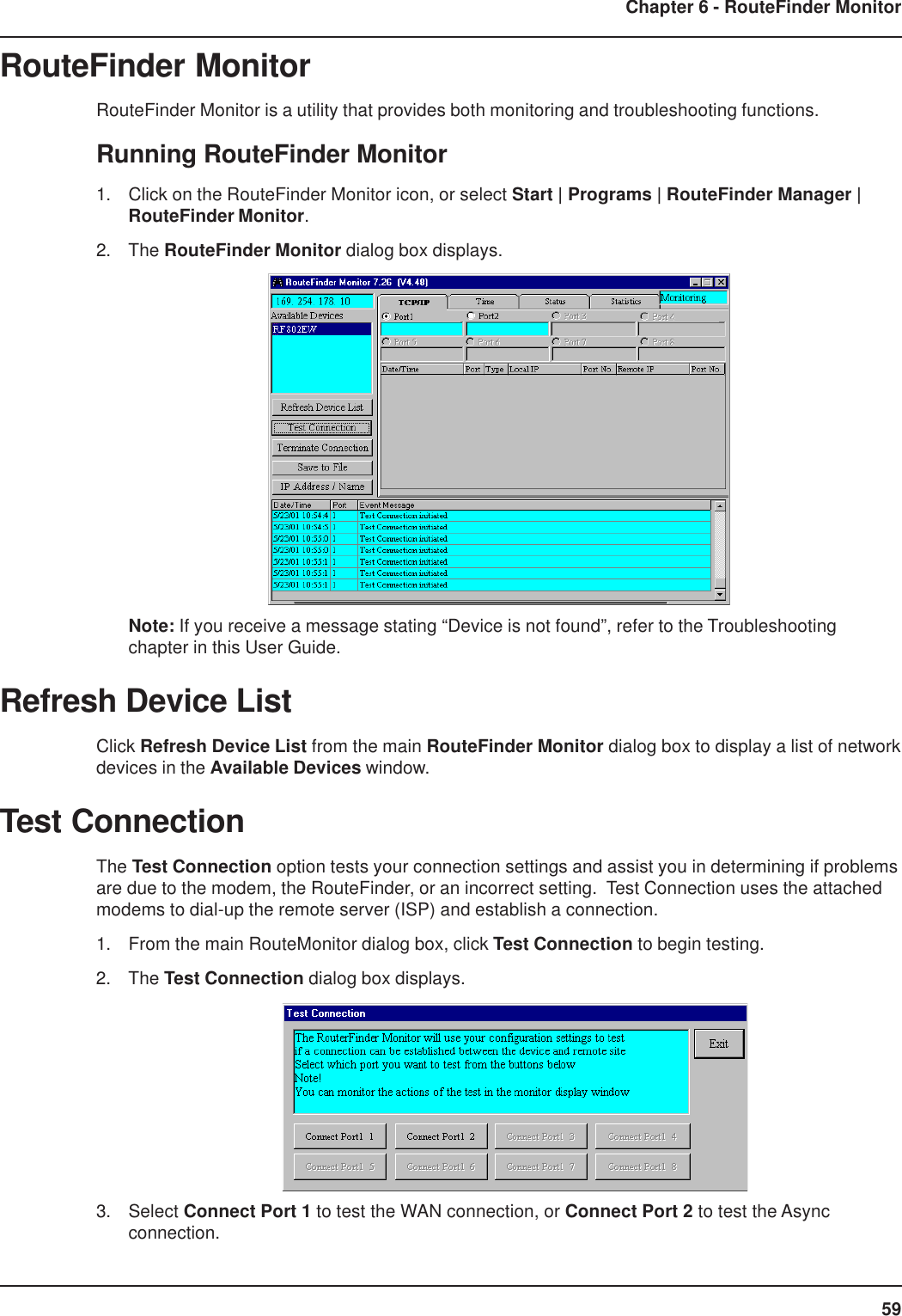
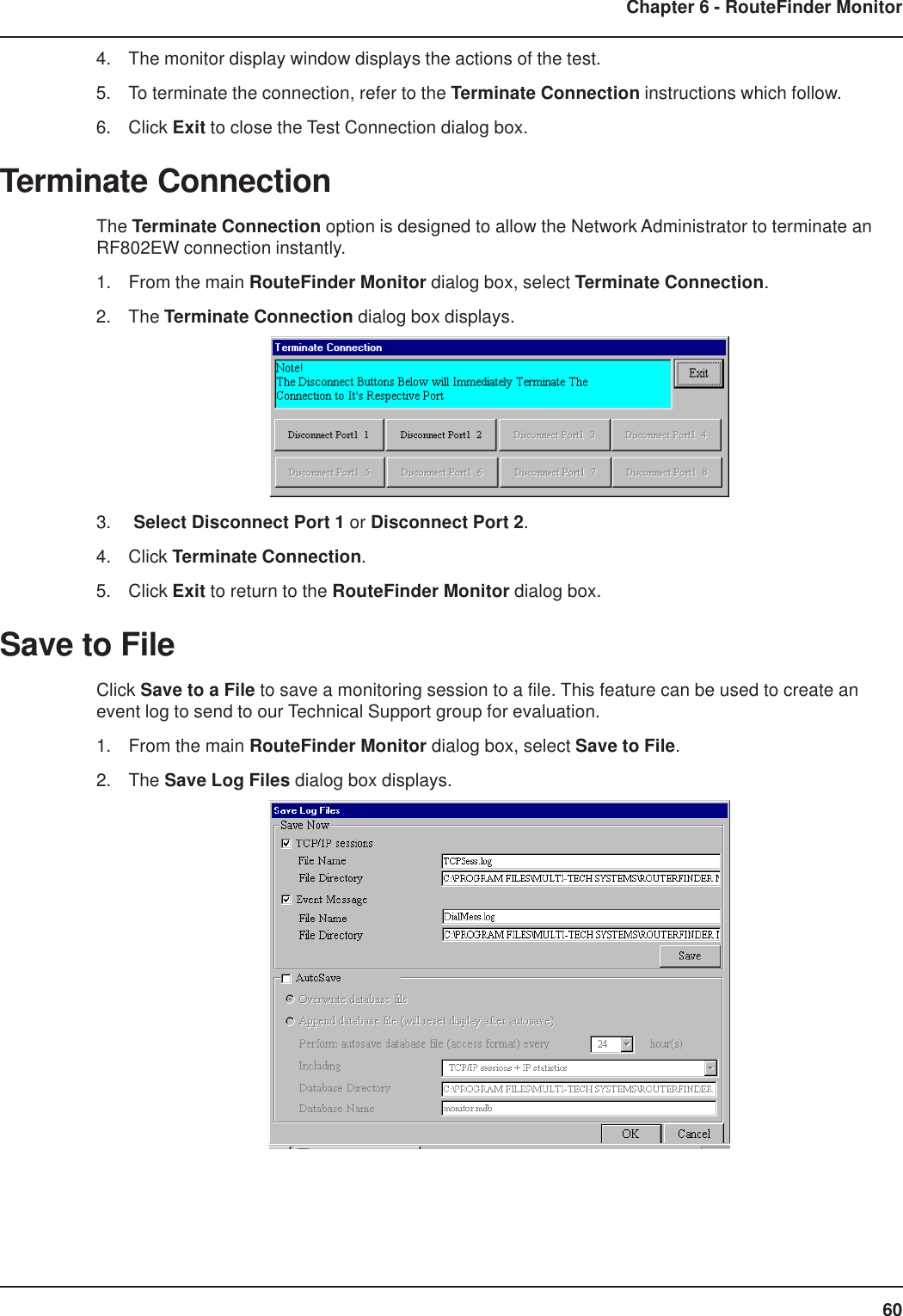
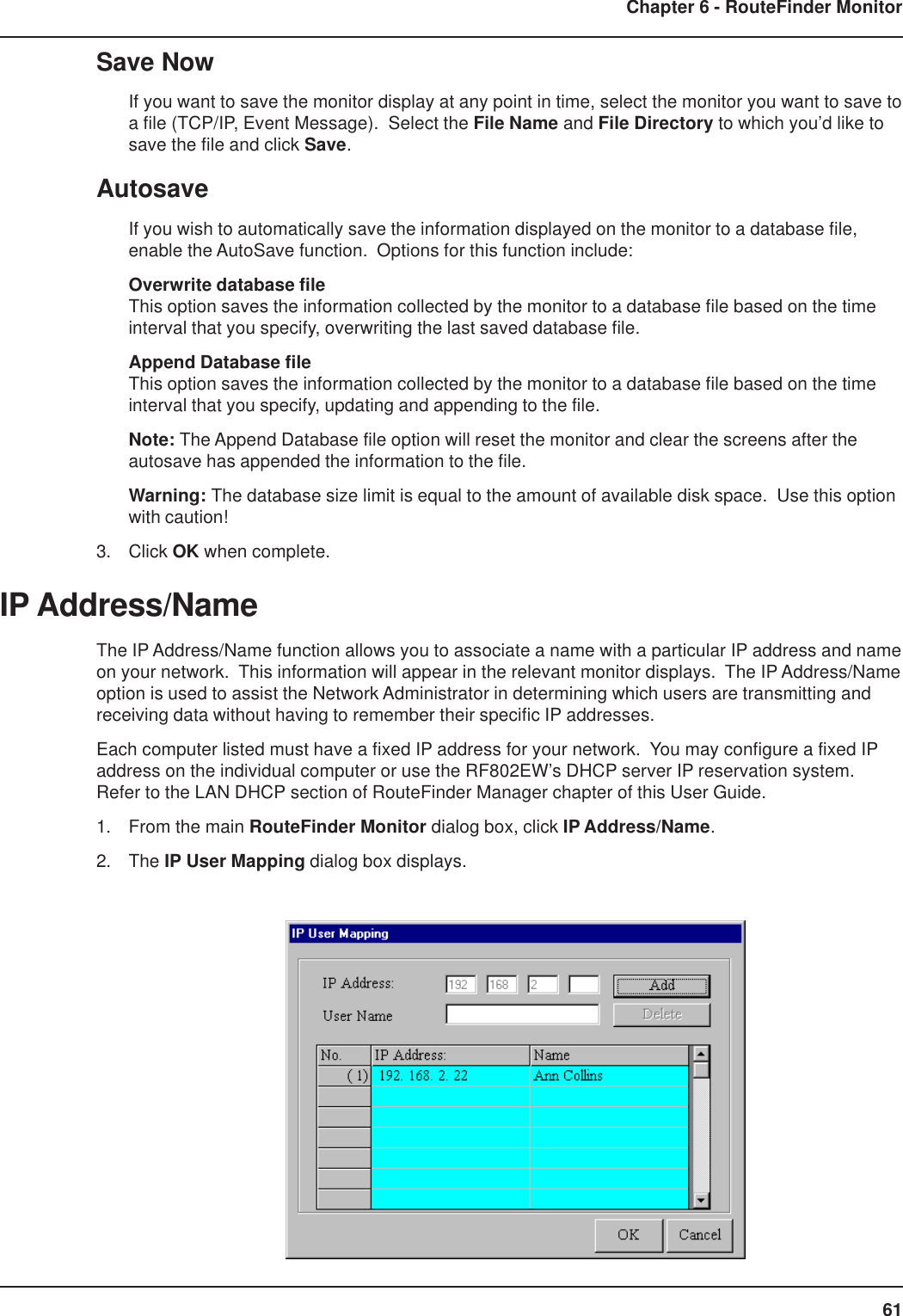
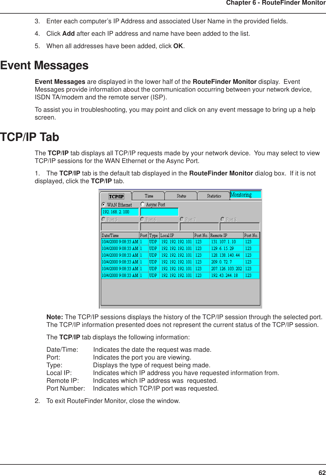
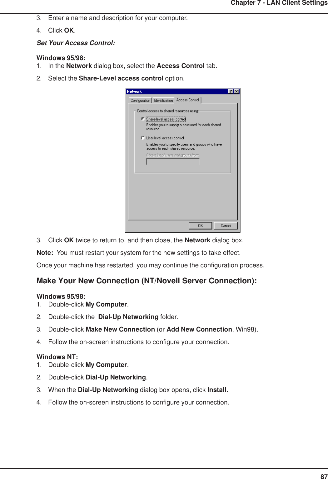
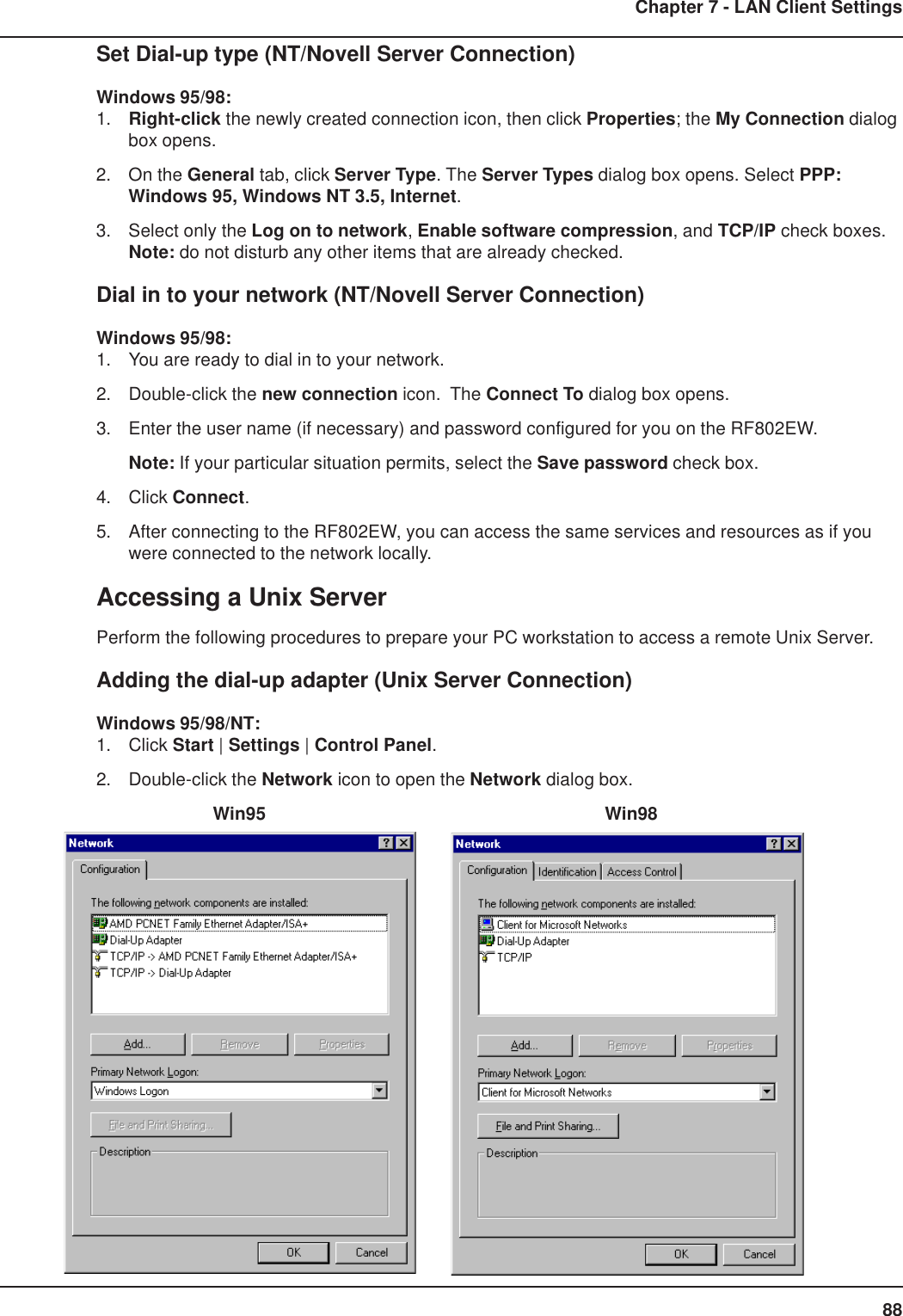
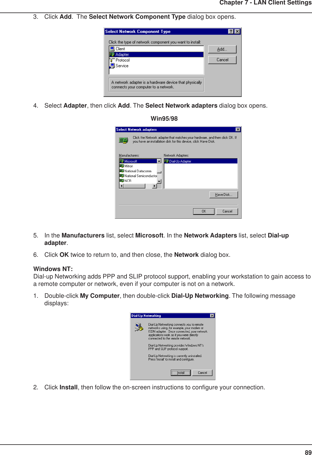
UserManual.wiki
>
Multi Tech Systems
>
92U01E04510 User Manual
Revised Users Manual
Navigation menu
Upload a User Manual
Namespaces
Wiki Guide
HTML
PDF
Info
Views
User Manual
Discussion / Help
Navigation
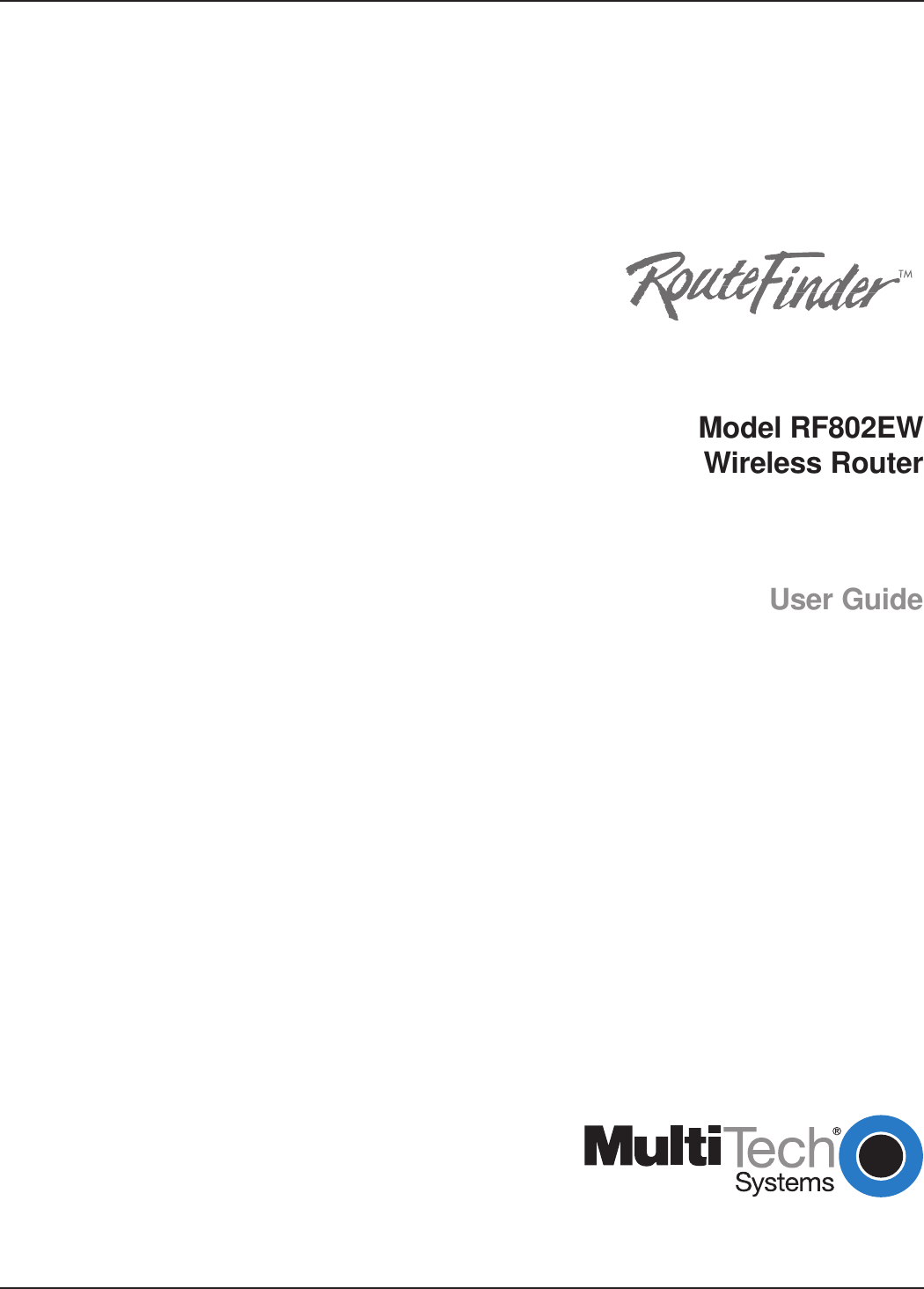


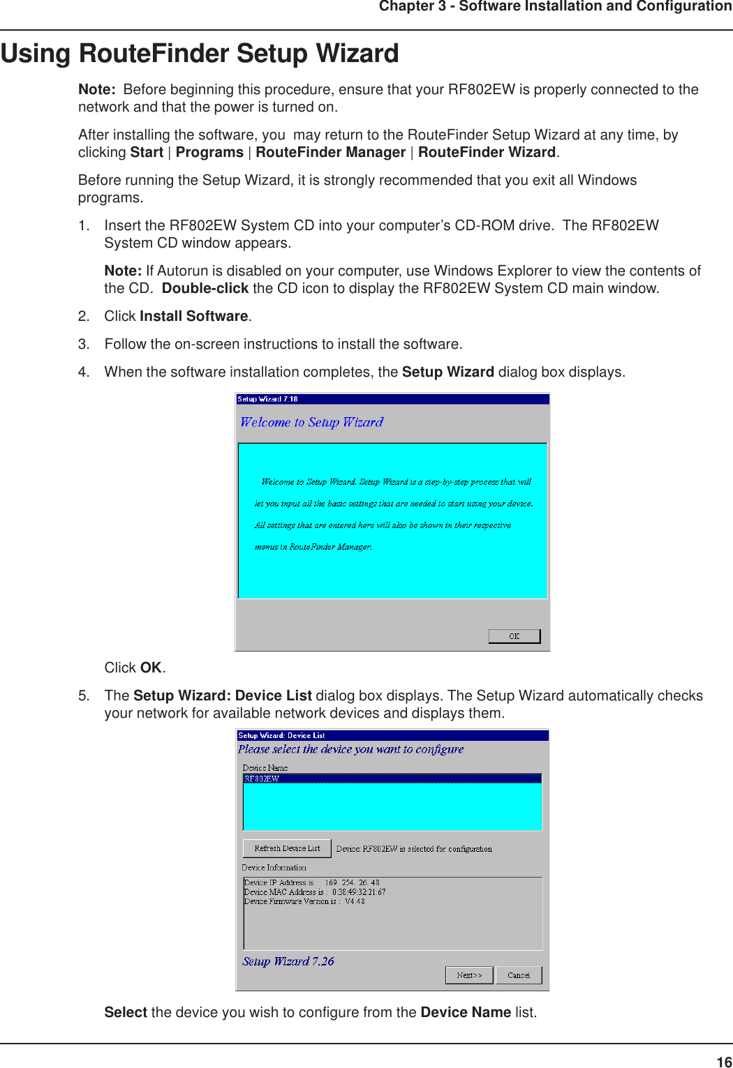
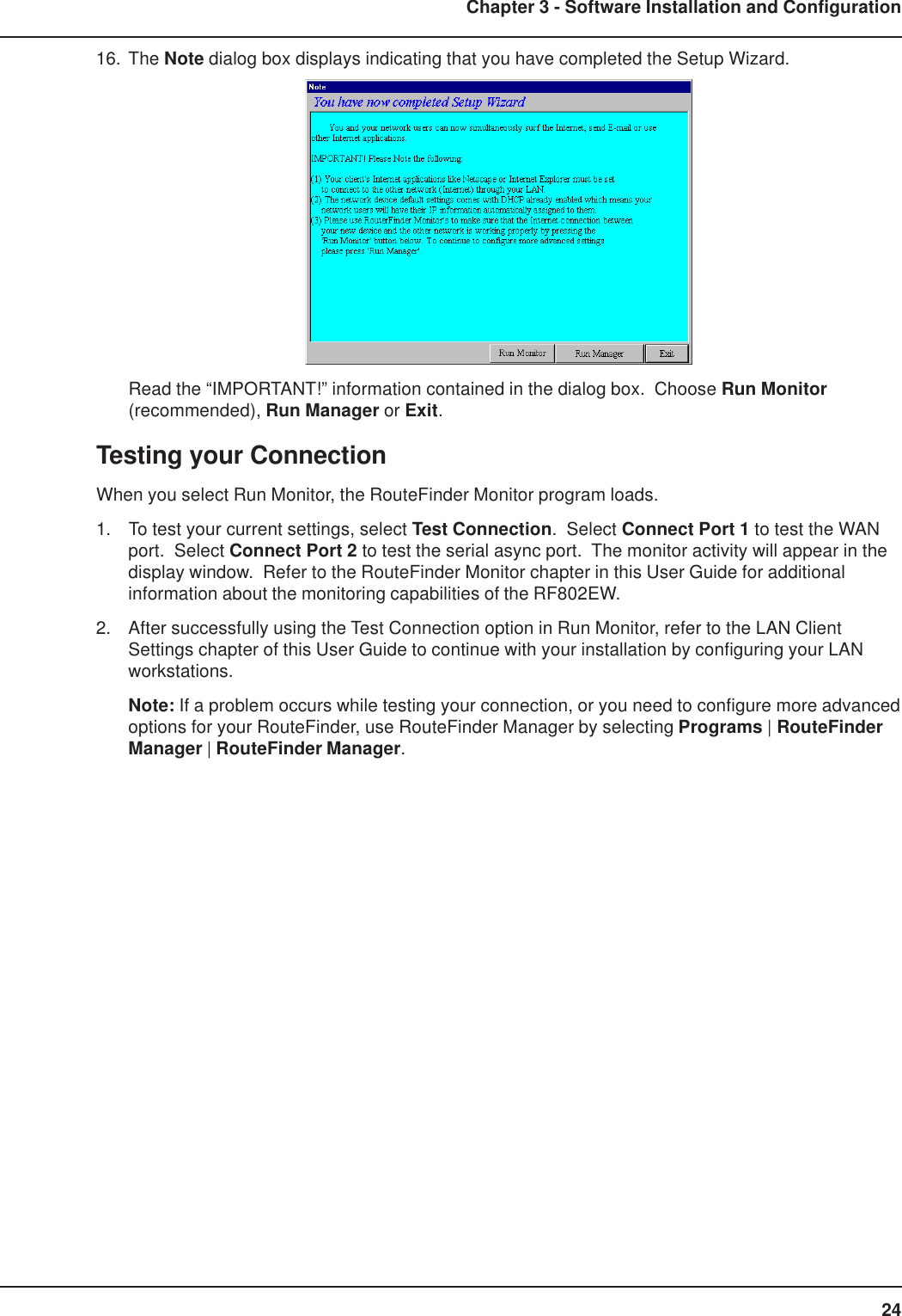


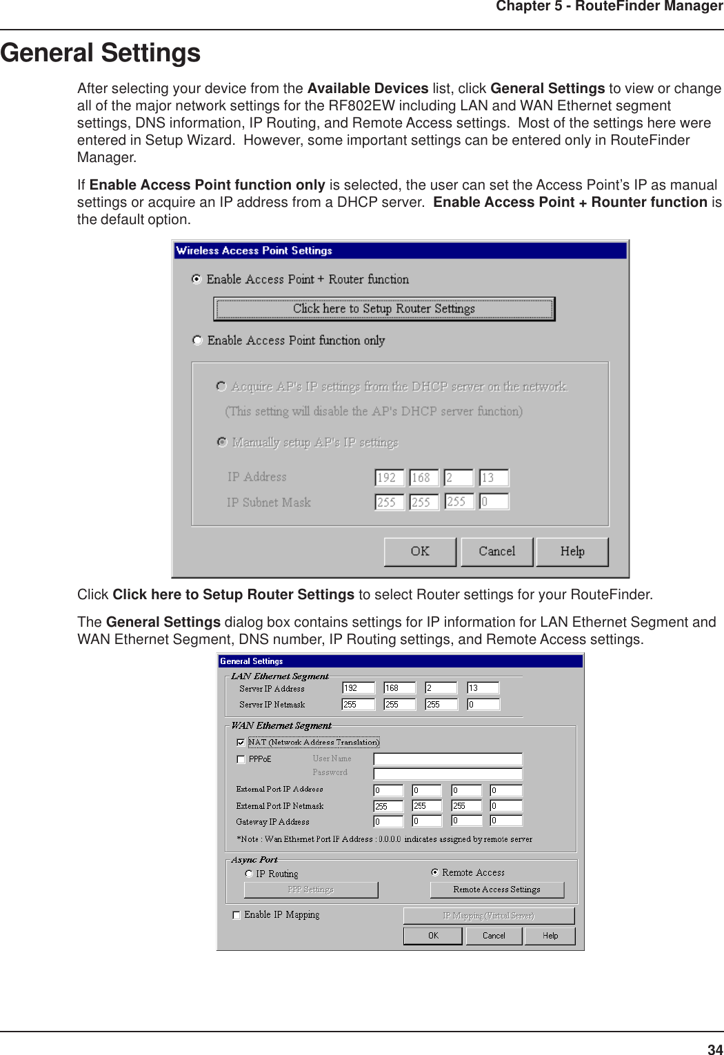
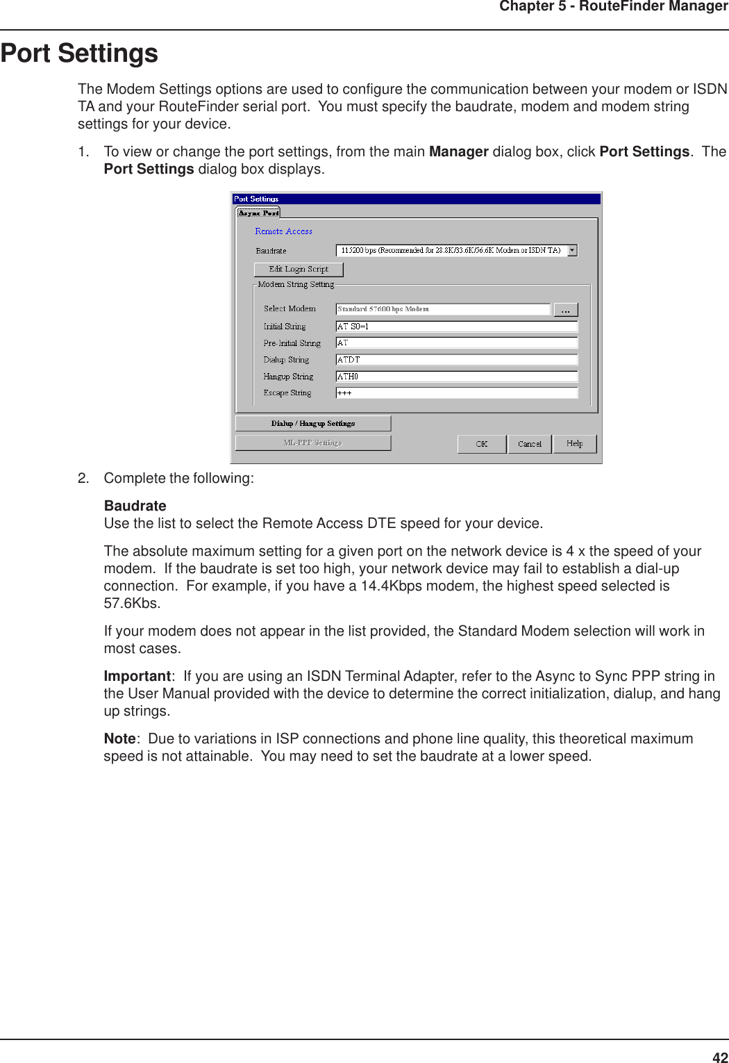

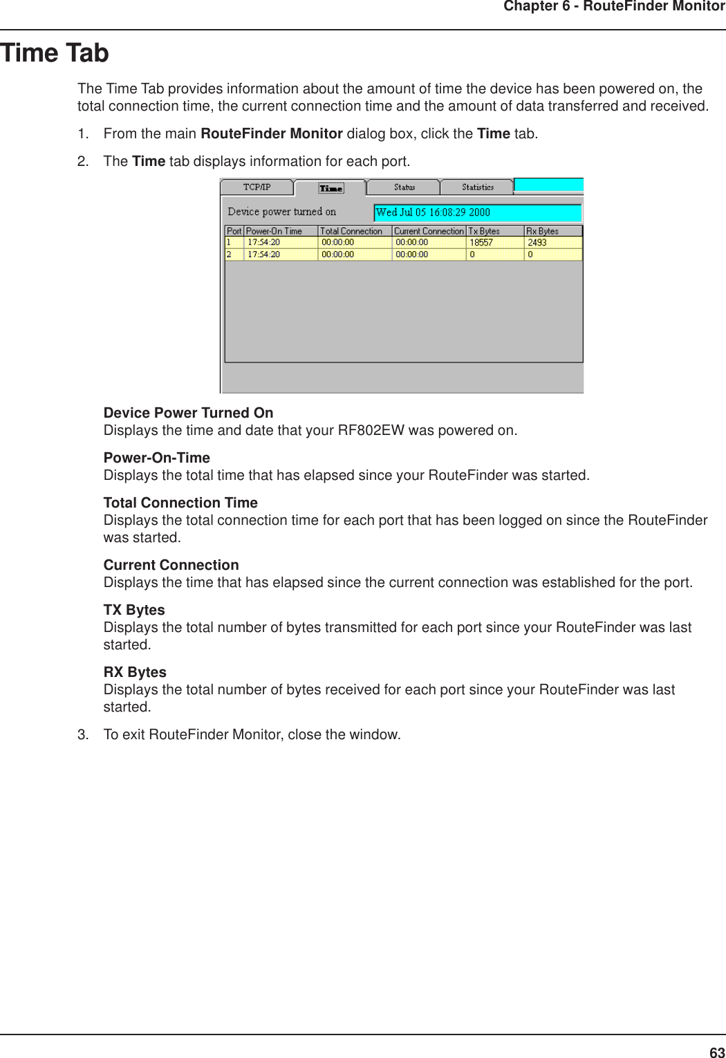

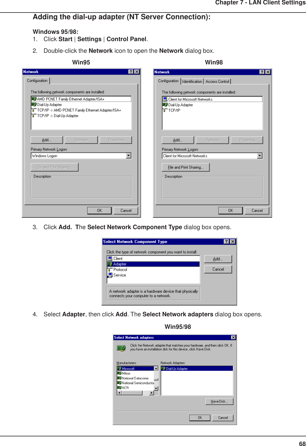
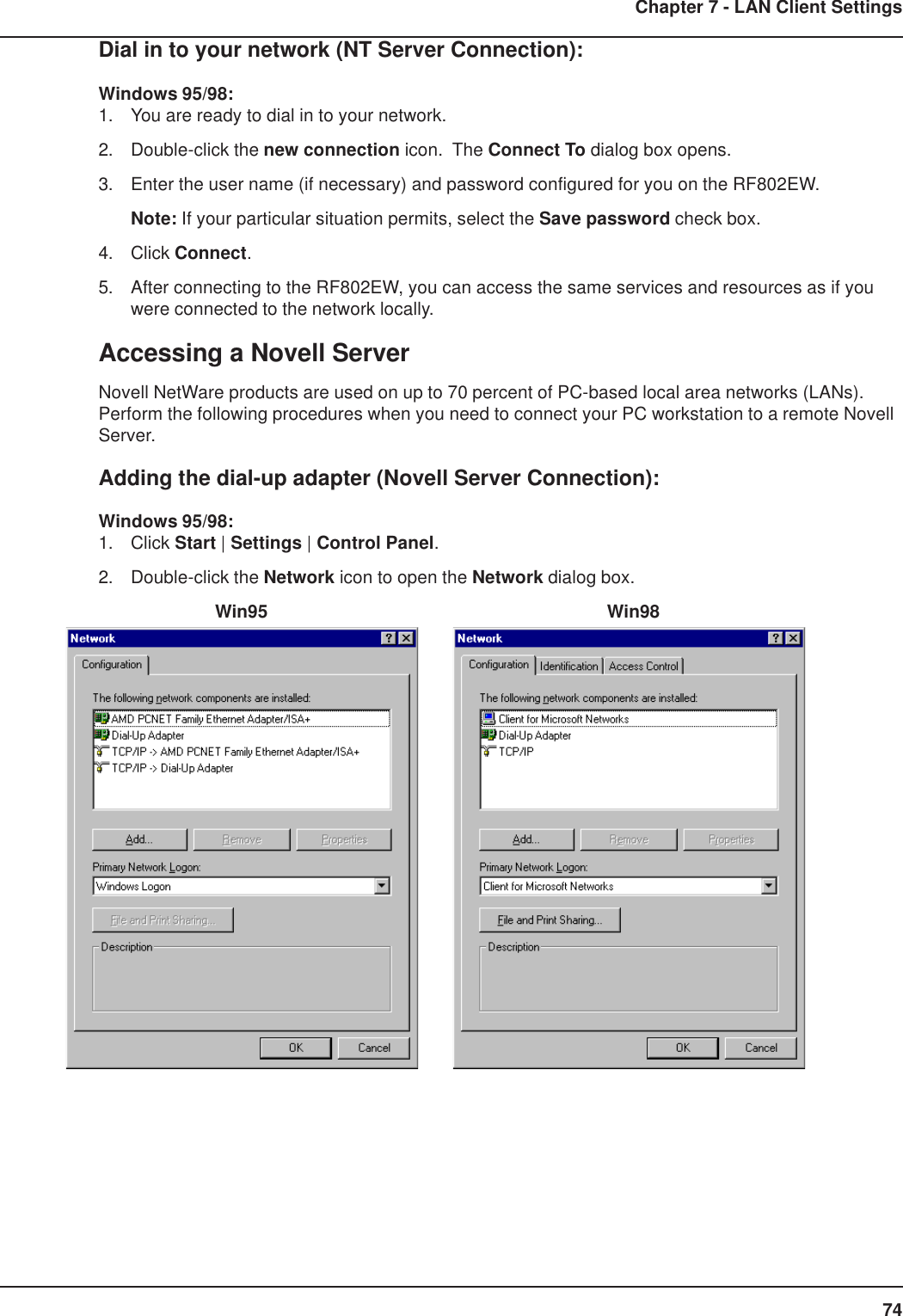
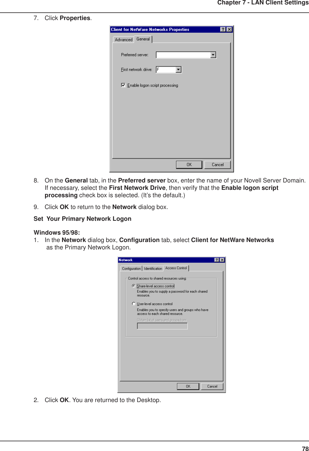
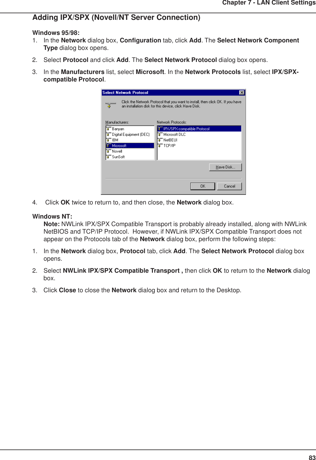
![69Chapter 7 - LAN Client Settings5. In the Manufacturers list, select Microsoft. In the Network Adapters list select Dial-up adapter.6. Click OK (twice) to return to, and then close, the Network dialog box.Windows NT:Dial-up Networking adds PPP and SLIP protocol support, enabling your workstation to gain access toa remote computer or network, even if your computer is not on a network.1. Double-click My Computer, then double-click Dial-Up Networking. The following screen isdisplayed:2. Click Install, then follow the onscreen instructions to configure your connection.Adding TCP/IP (NT Server Connection):Windows 95/98/NT:1. In the Network dialog box, Configuration tab, click Add.2. Select Protocol and click Add.3. The Select Network Protocol dialog box is displayed. In the Manufacturers list [Win95 only],select Microsoft. In the Network Protocols list, select TCP/IP [Win95/98] or TCP/IP Protocol[WinNT only].[Note: Windows NT workstation has no Manufacturers list.] Win95/98 WinNT4. Click OK twice to return to, and then close, the Network dialog box.](https://usermanual.wiki/Multi-Tech-Systems/92U01E04510/User-Guide-155441-Page-69.png)
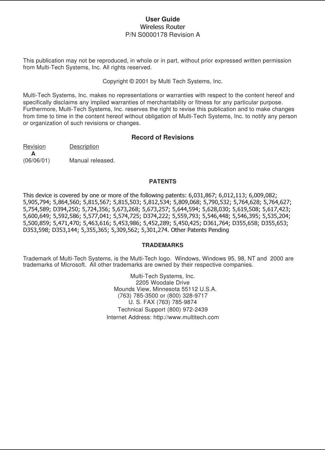
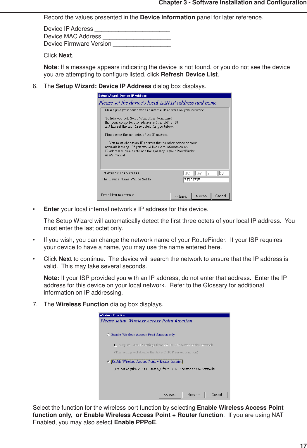
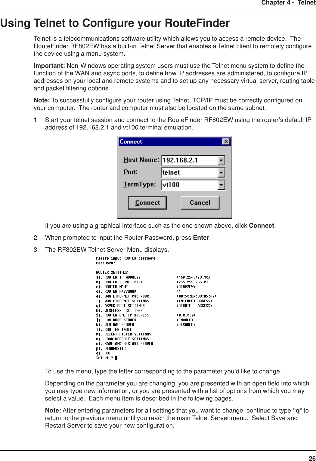
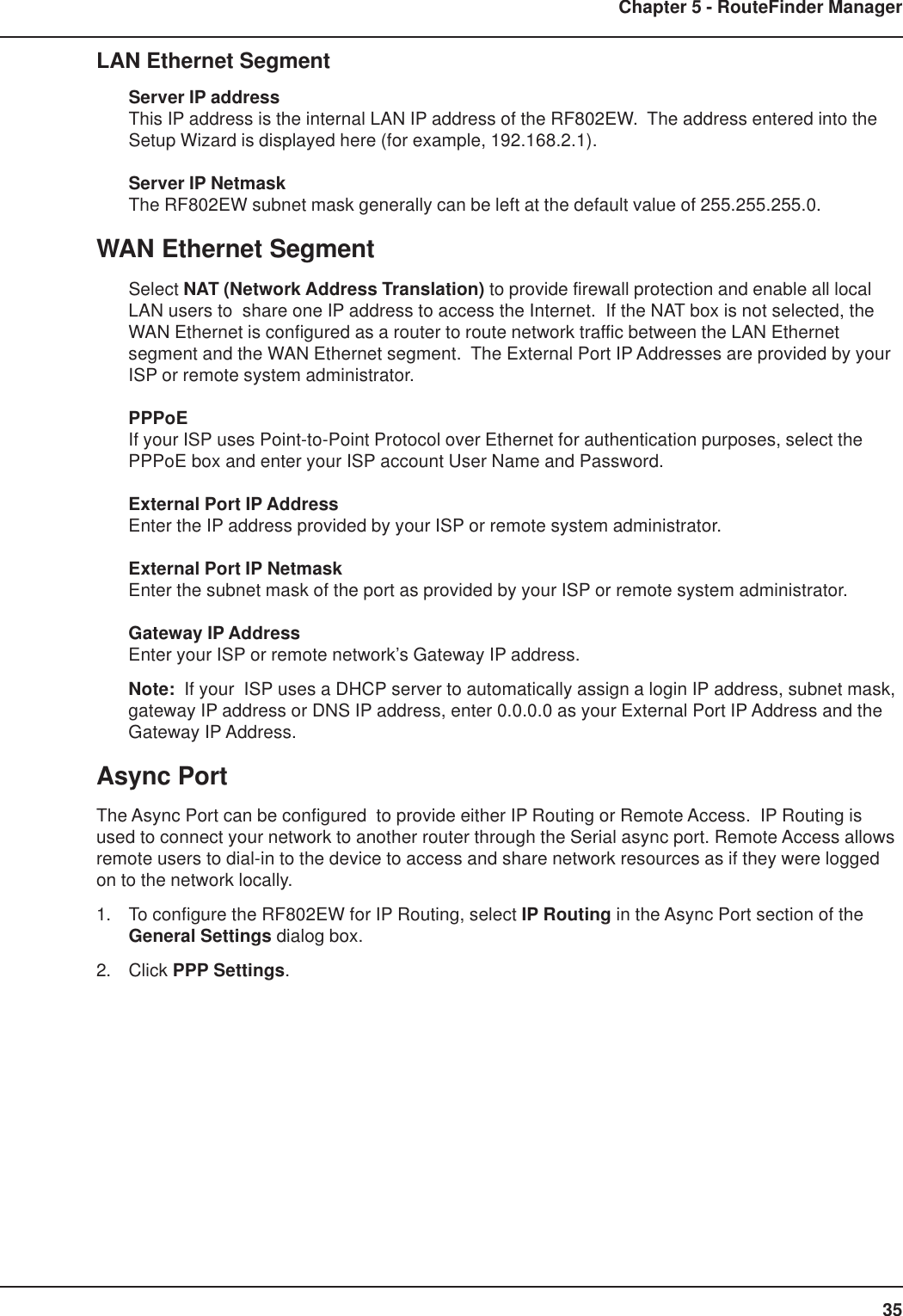
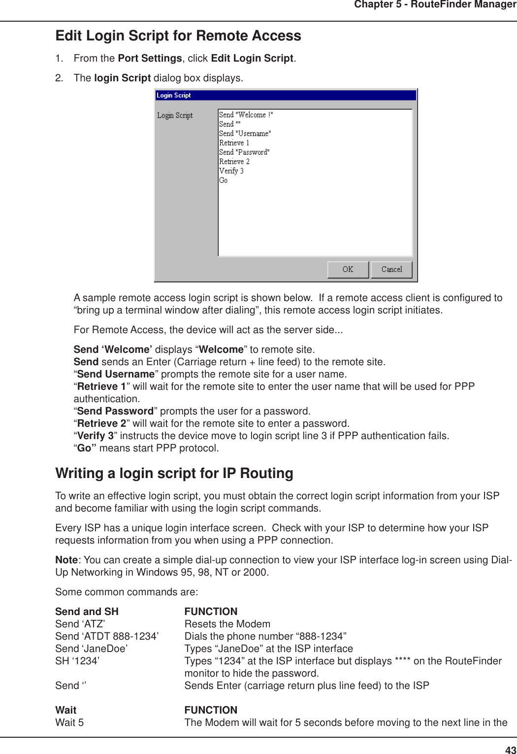
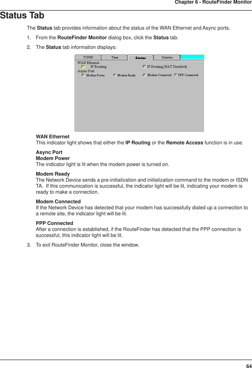
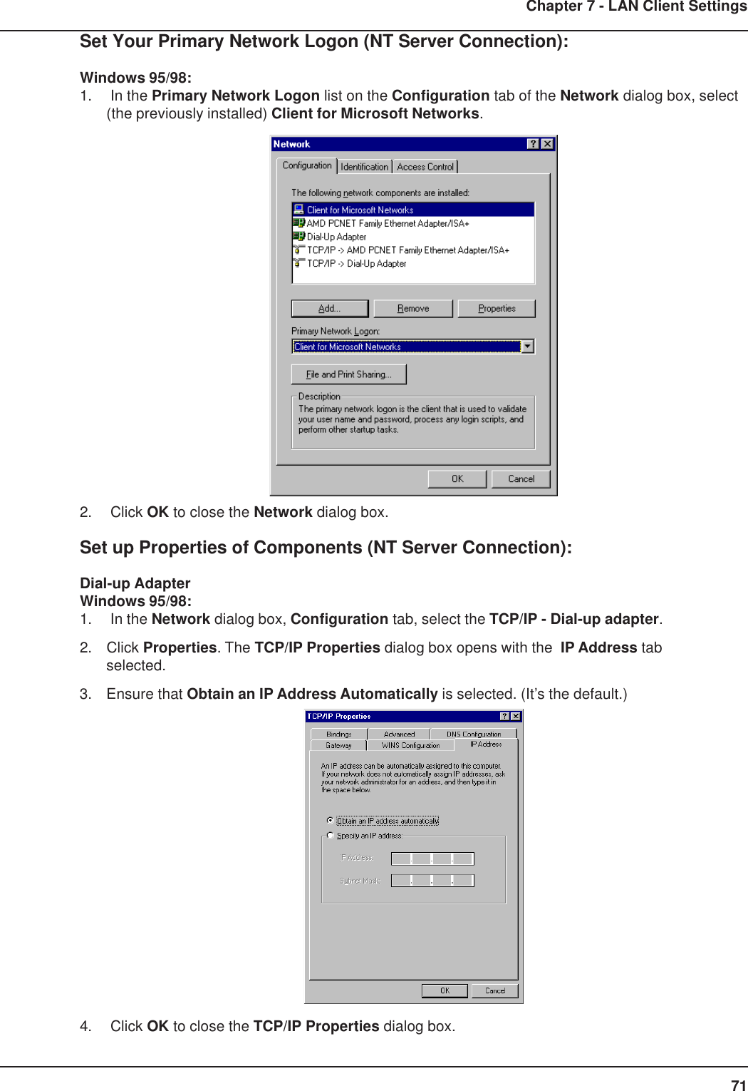
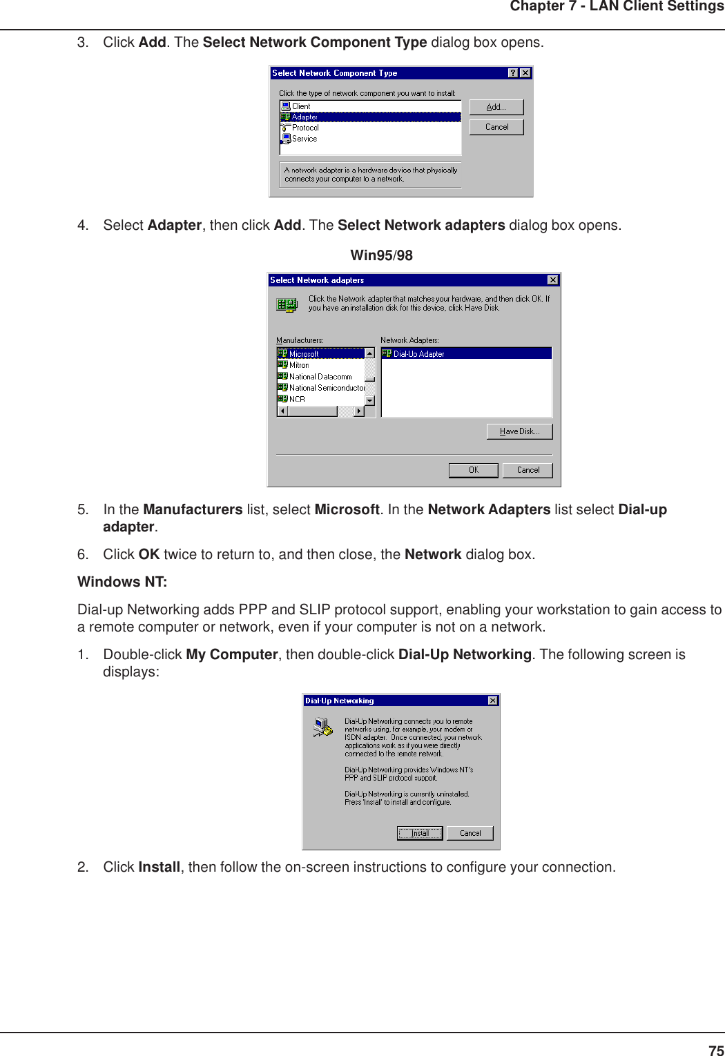
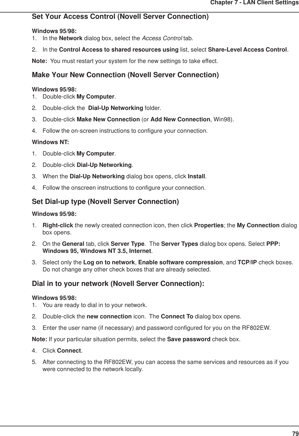
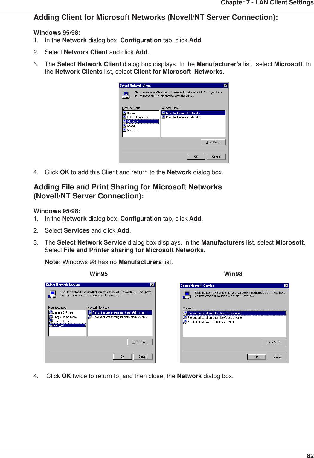
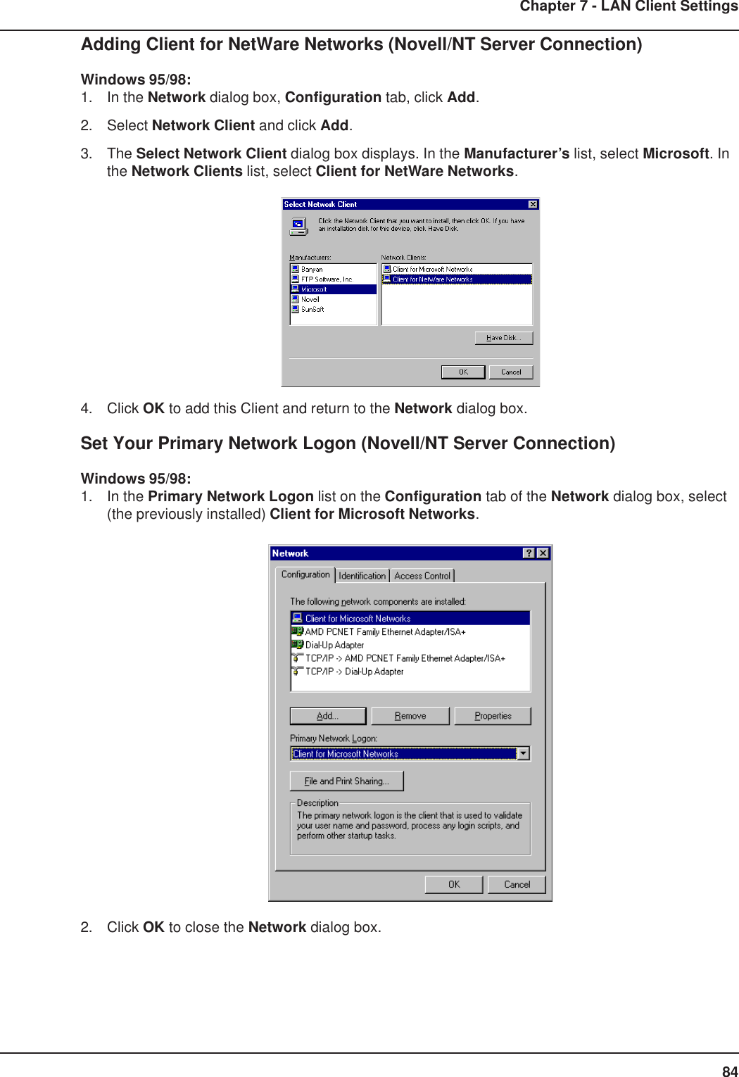
![70Chapter 7 - LAN Client SettingsAdding Client for Microsoft Networks (NT Server Connection):Windows 95/98:1. In the Network dialog box, Configuration tab, click Add.2. Select Network Client and click Add.3. The Select Network Client dialog box displays. In the Manufacturer’s list, select Microsoft. Inthe Network Clients list, select Client for Microsoft Networks.4. Click OK to add this Client and return to the Network dialog box.Adding File and Print Sharing for Microsoft Networks (NT Server Connection):Windows 95/98:1. In the Network dialog box, Configuration tab, click Add.2. Select Services and click Add.3. The Select Network Service dialog box displays. In the Manufacturers list, select Microsoft.Select File and Printer sharing for Microsoft Networks.[Note: Windows 98 has no Manufacturers list.]Win95 Win984. Click OK twice to return to, and then close, the Network dialog box.](https://usermanual.wiki/Multi-Tech-Systems/92U01E04510/User-Guide-155441-Page-70.png)
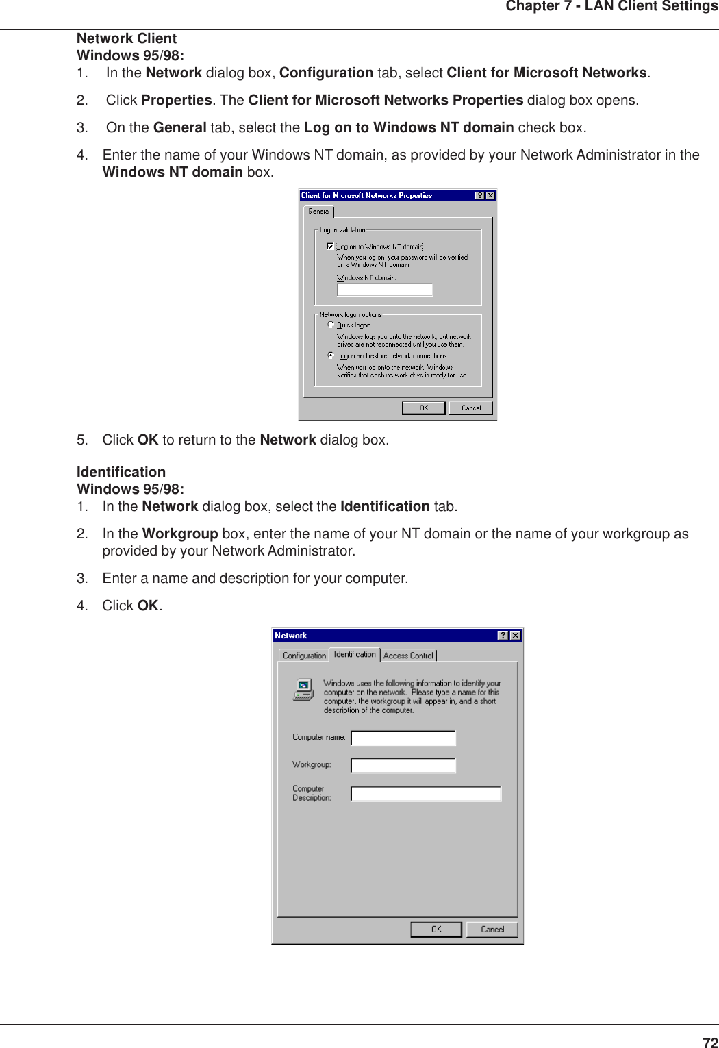
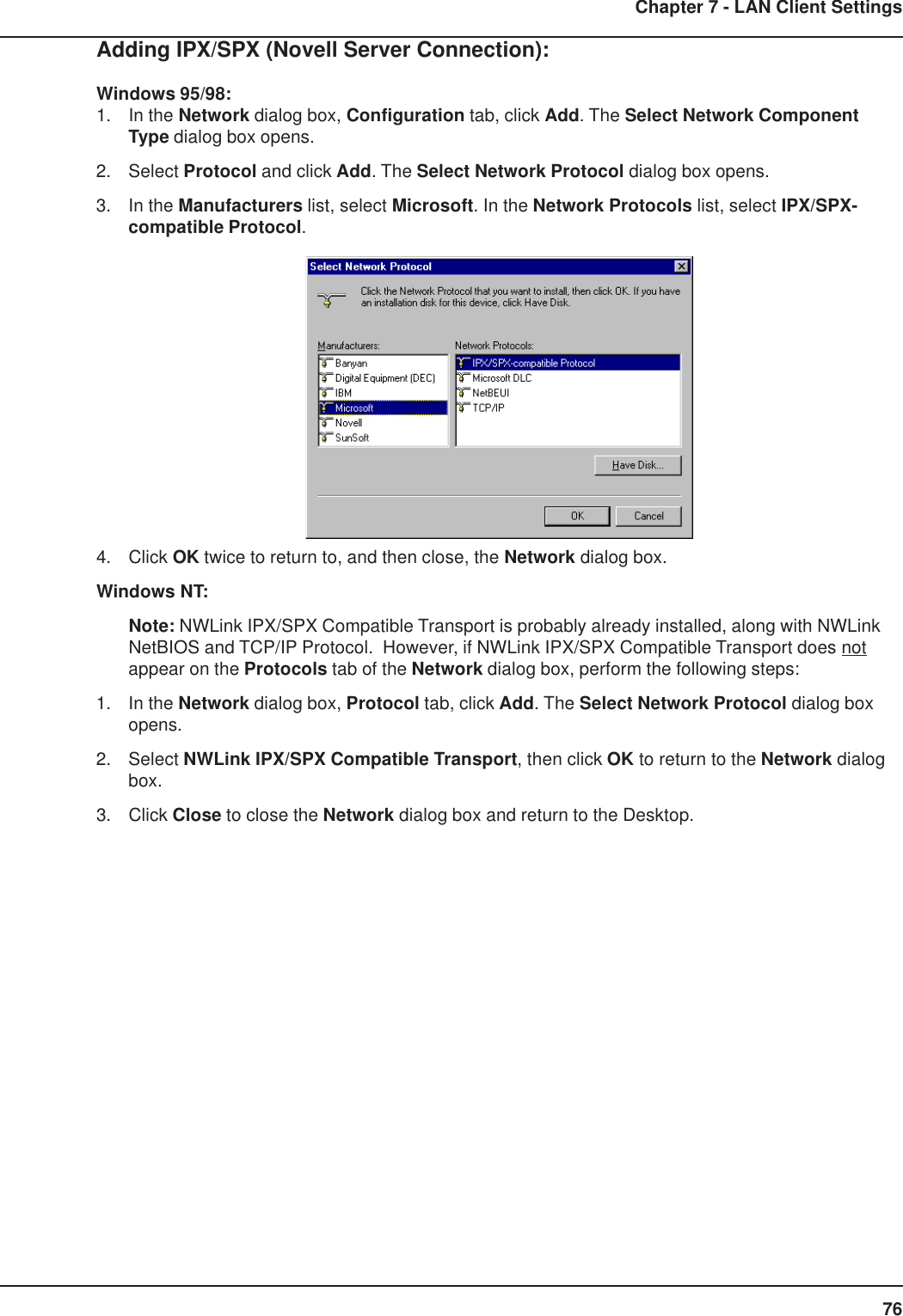
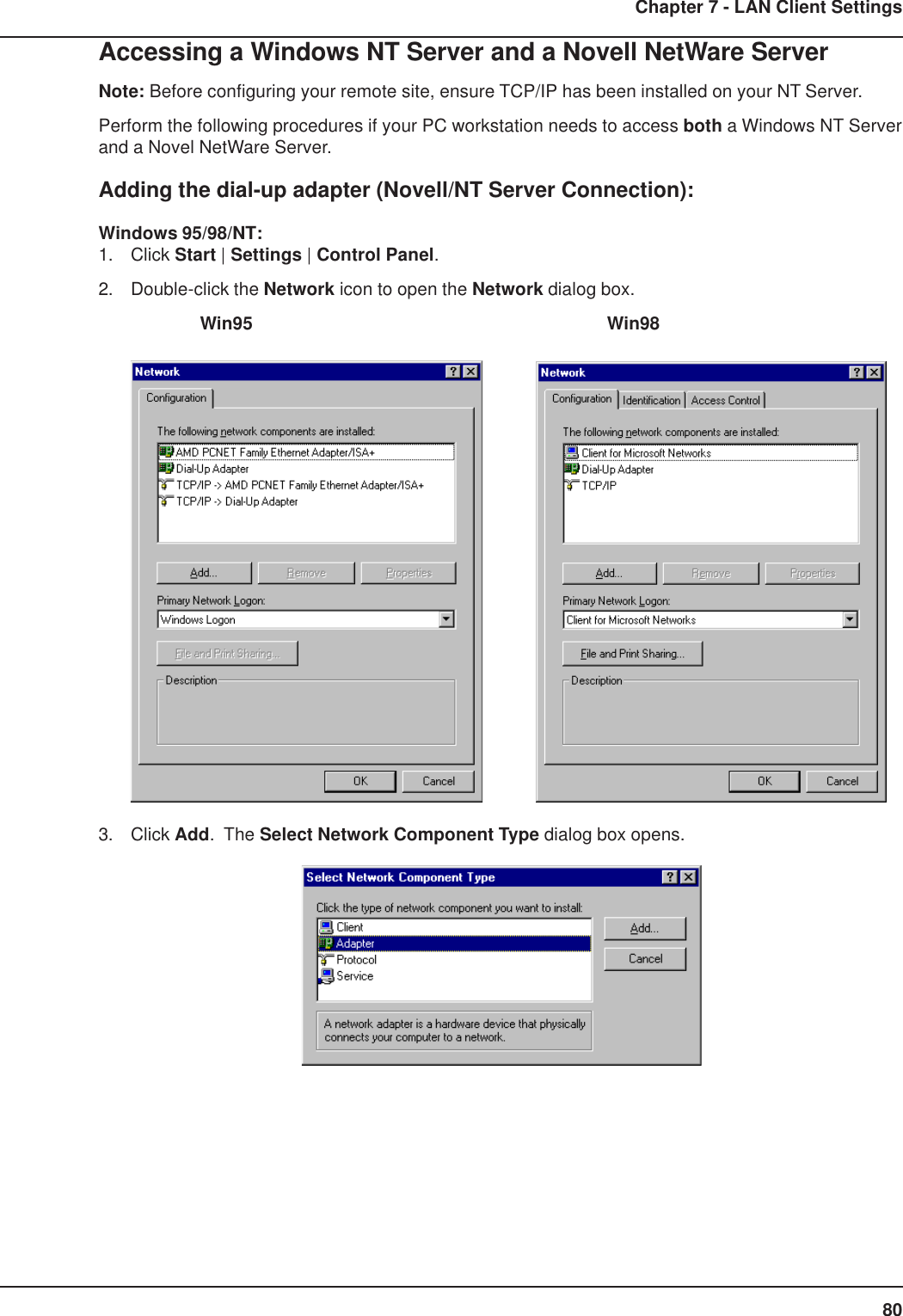
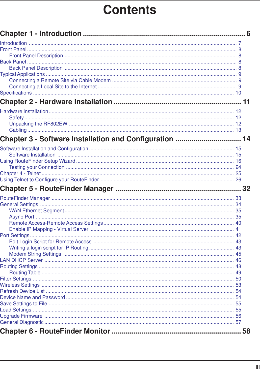
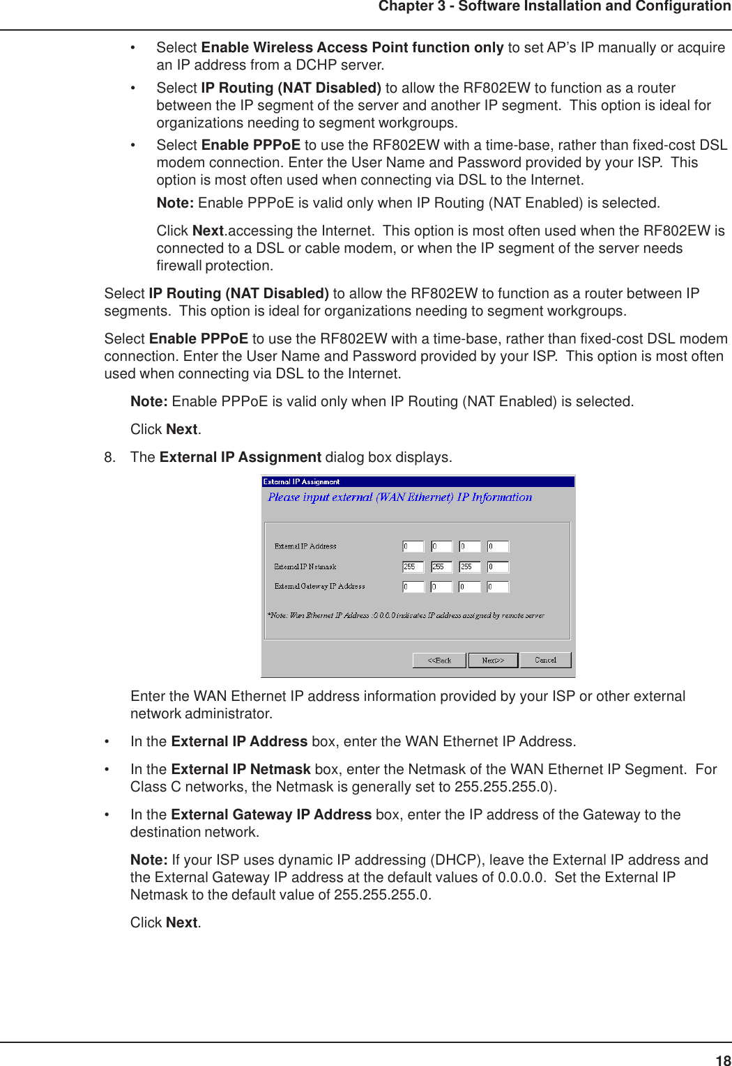
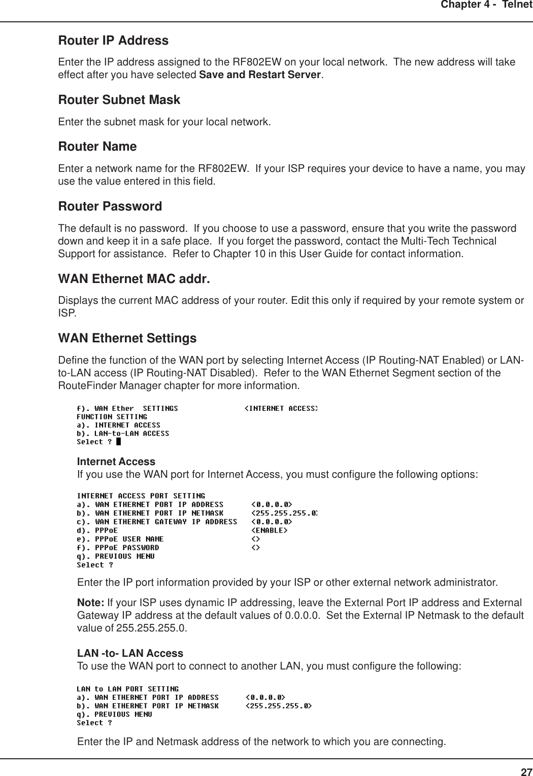
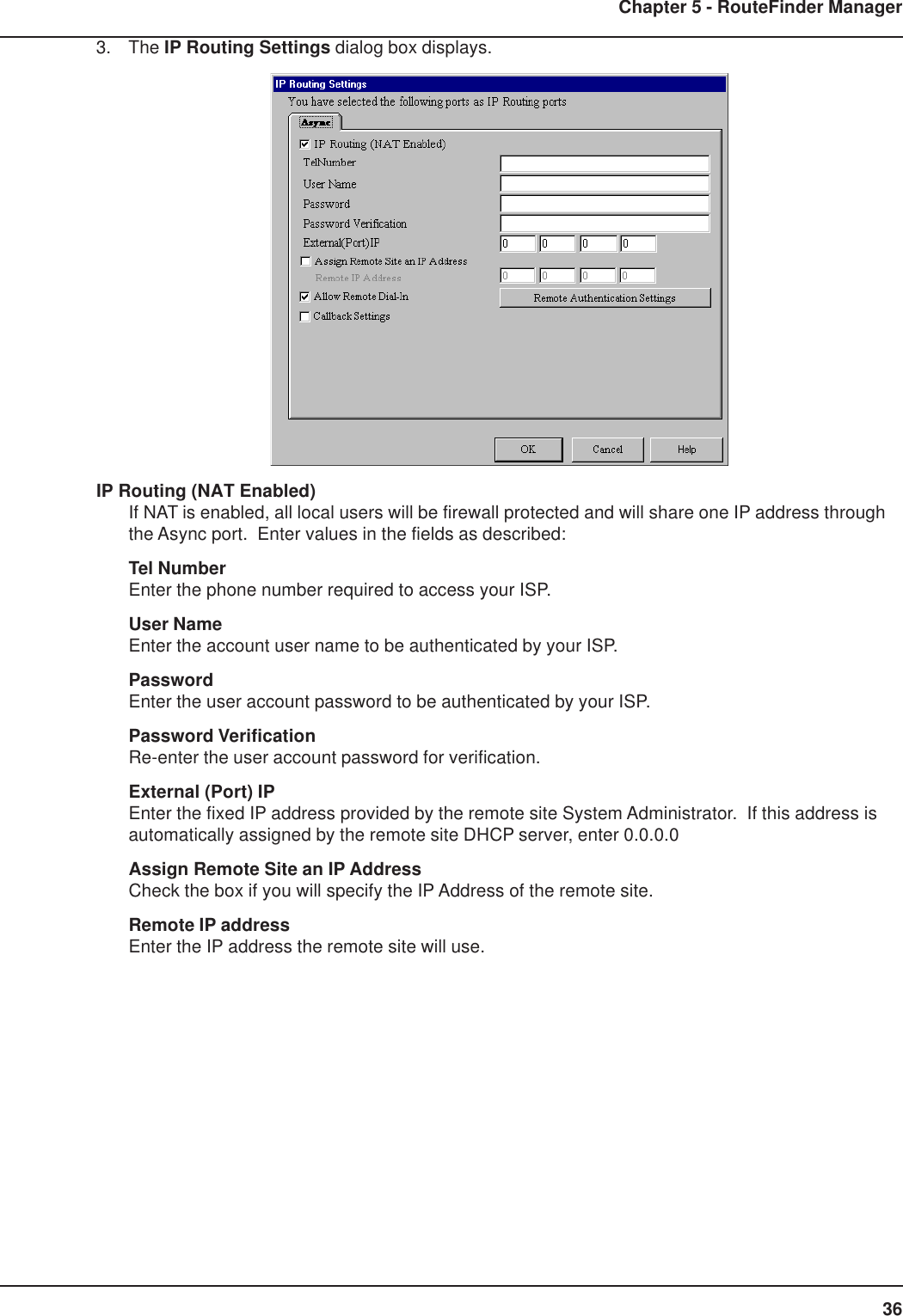
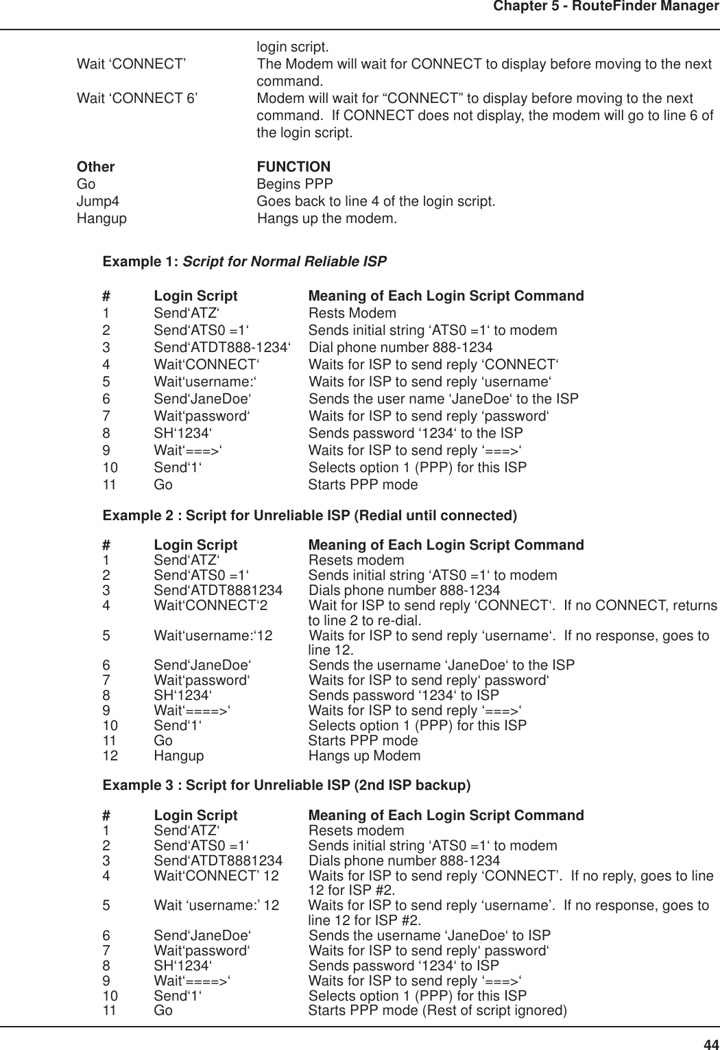
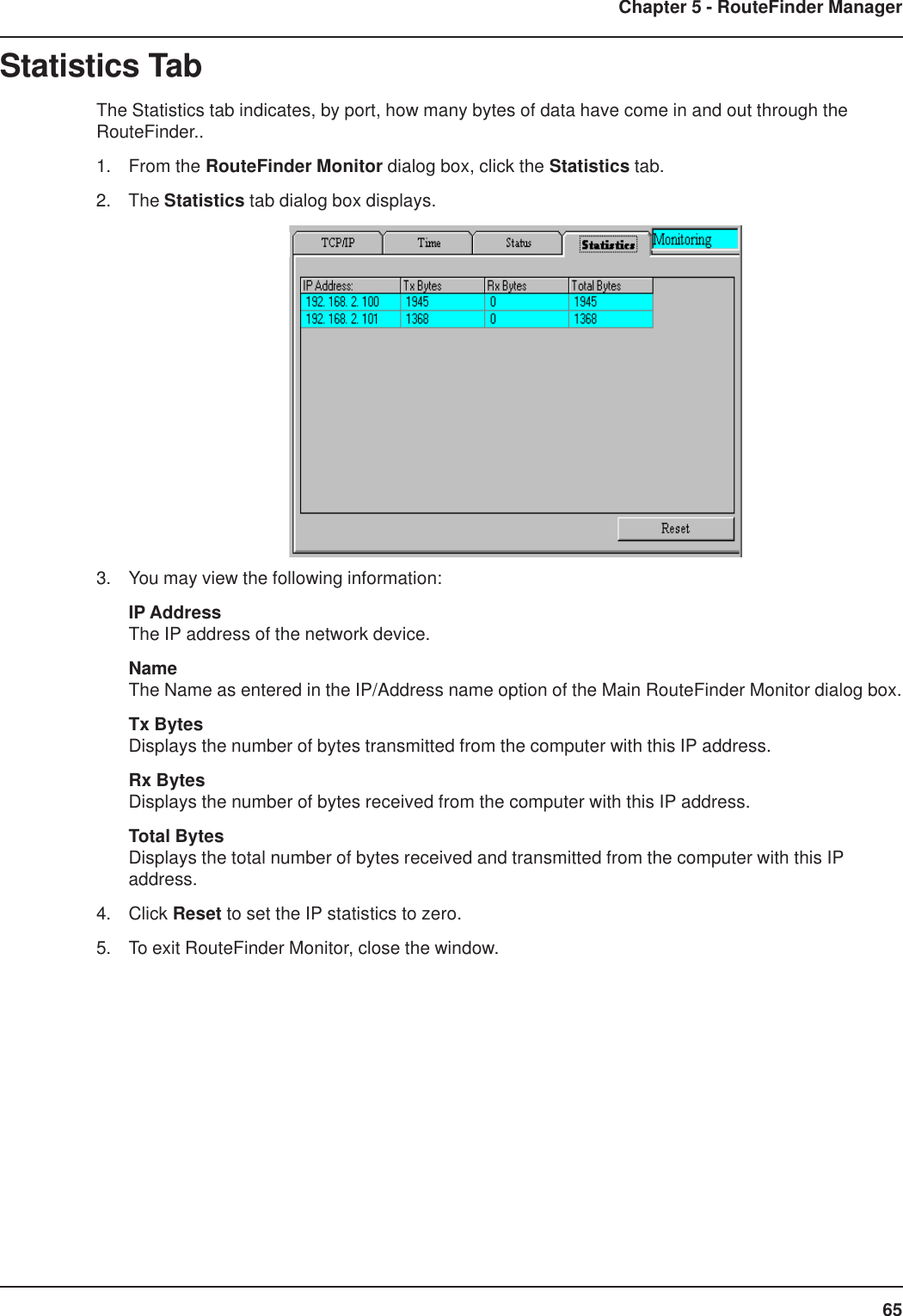
![81Chapter 7 - LAN Client Settings4. Select Adapter, then click Add. The Select Network adapters dialog box opens. Win95/98 WinNT5. (Win95/98 only) In the Manufacturers list, select Microsoft. In the Network Adapters list selectDial-up adapter.Note: In Windows NT workstation there is no Manufacturers list.6. Click OK twice to return to, and then close, the Network dialog box.Adding TCP/IP (Novell/NT Server Connection):Windows 95/98/NT:1. In the Network dialog box, Configuration tab, click Add.2. Select Protocol and click Add.3. The Select Network Protocol dialog box is displayed. In the Manufacturers list [Win95 only],select Microsoft. In the Network Protocols list, select TCP/IP [Win95/98] or TCP/IP Protocol[WinNT only].Note: Windows NT workstation has no Manufacturers list. Win95/98 WinNT4. Click OK twice to return to, and then close, the Network dialog box.](https://usermanual.wiki/Multi-Tech-Systems/92U01E04510/User-Guide-155441-Page-81.png)
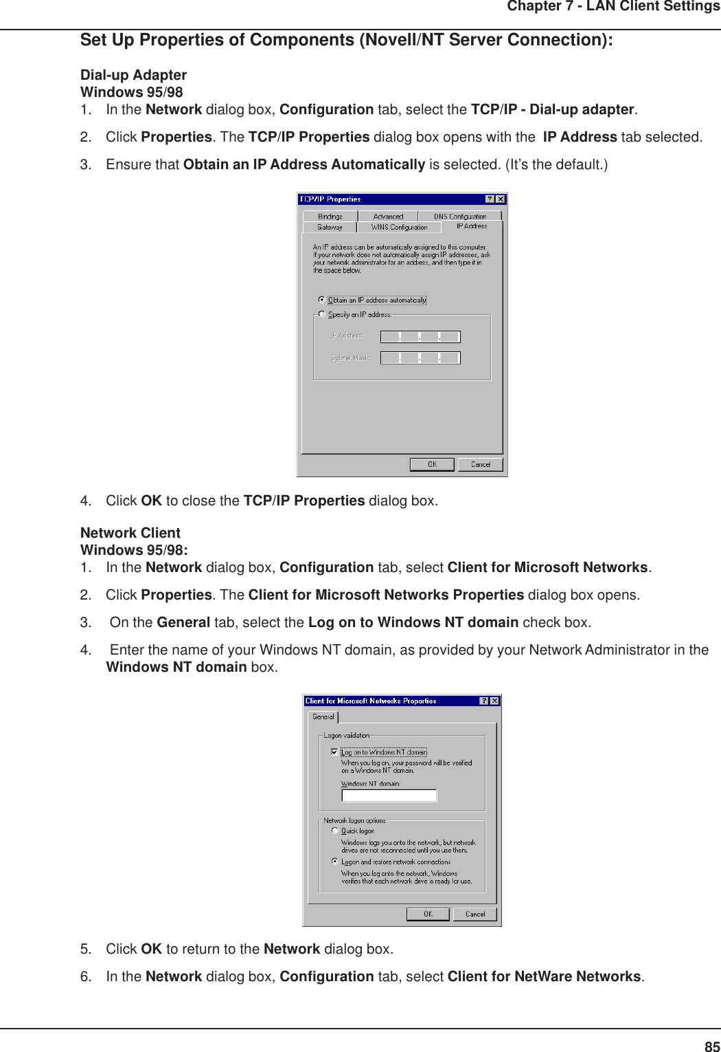
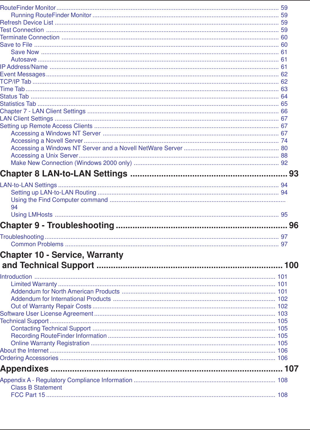
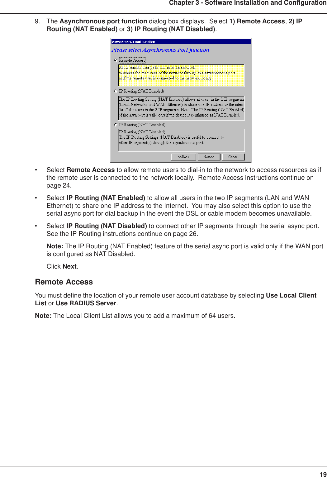
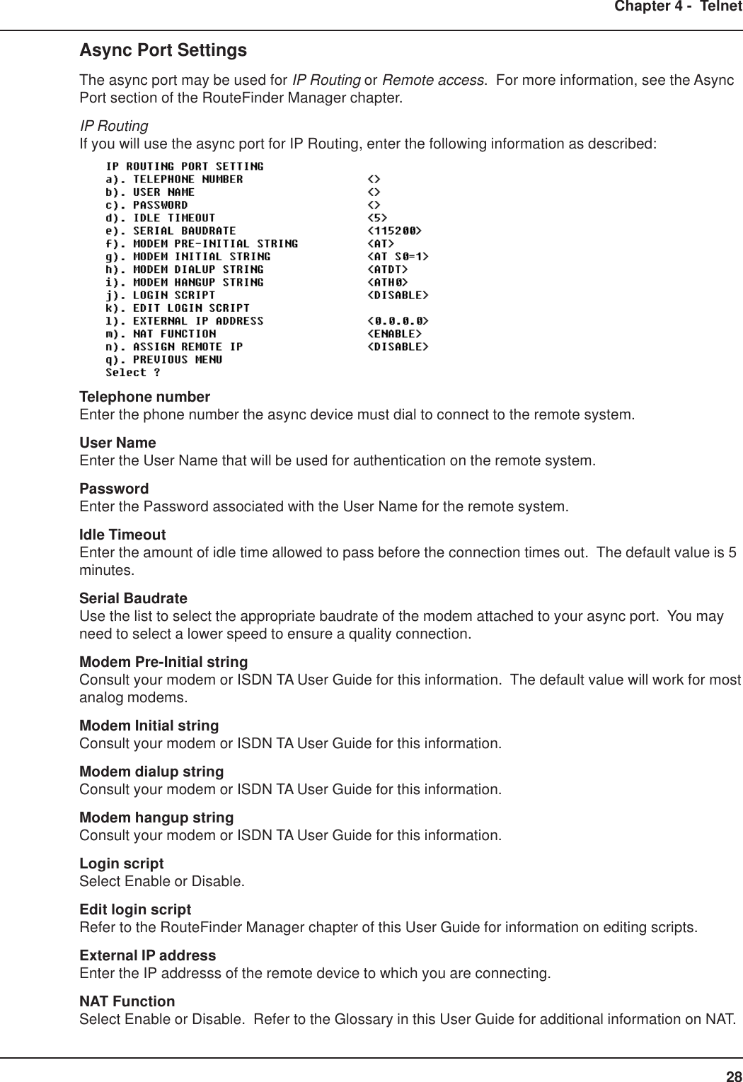
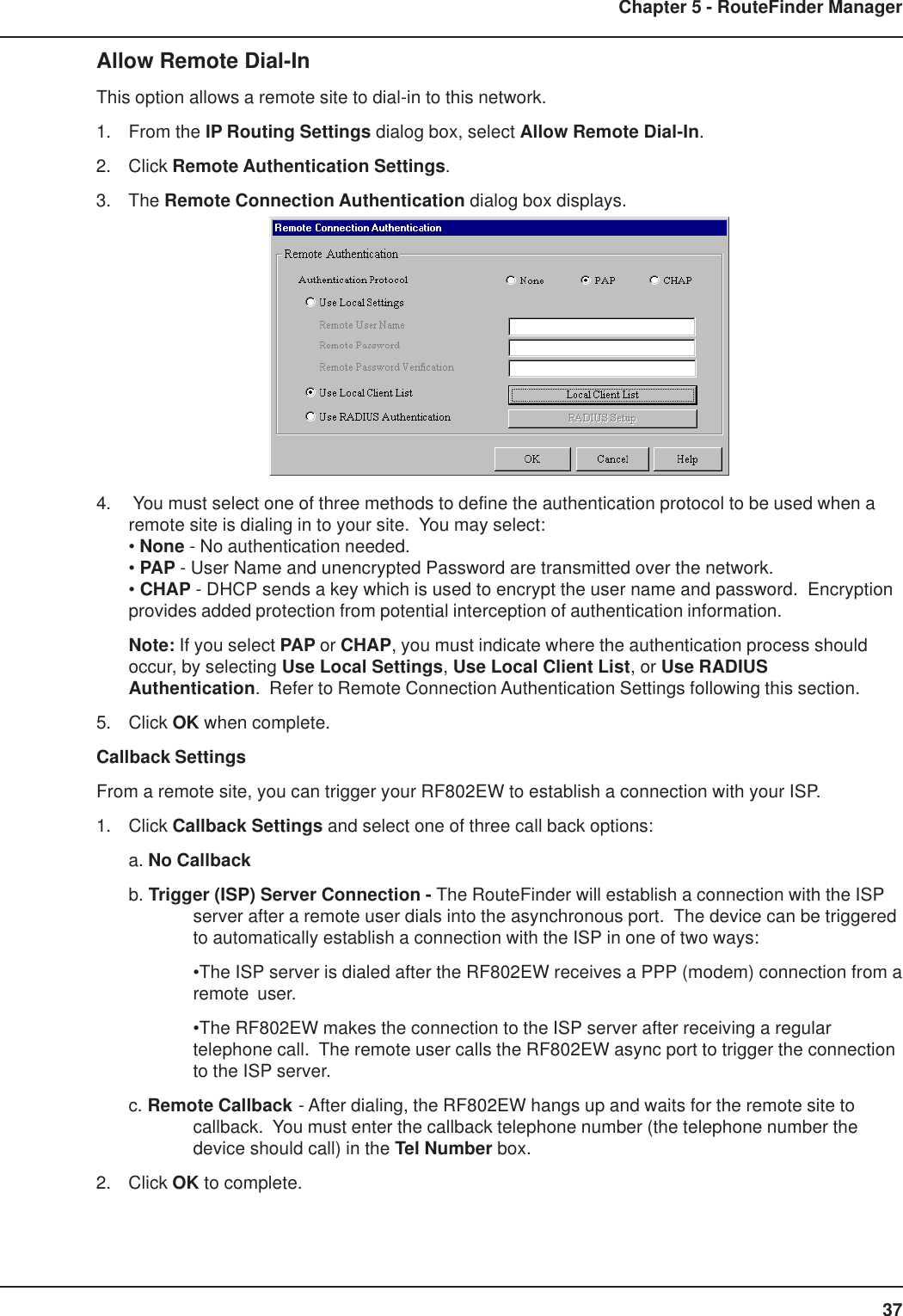
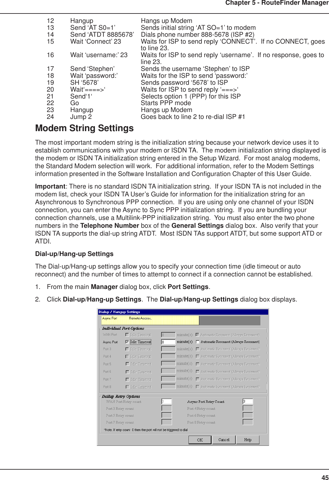
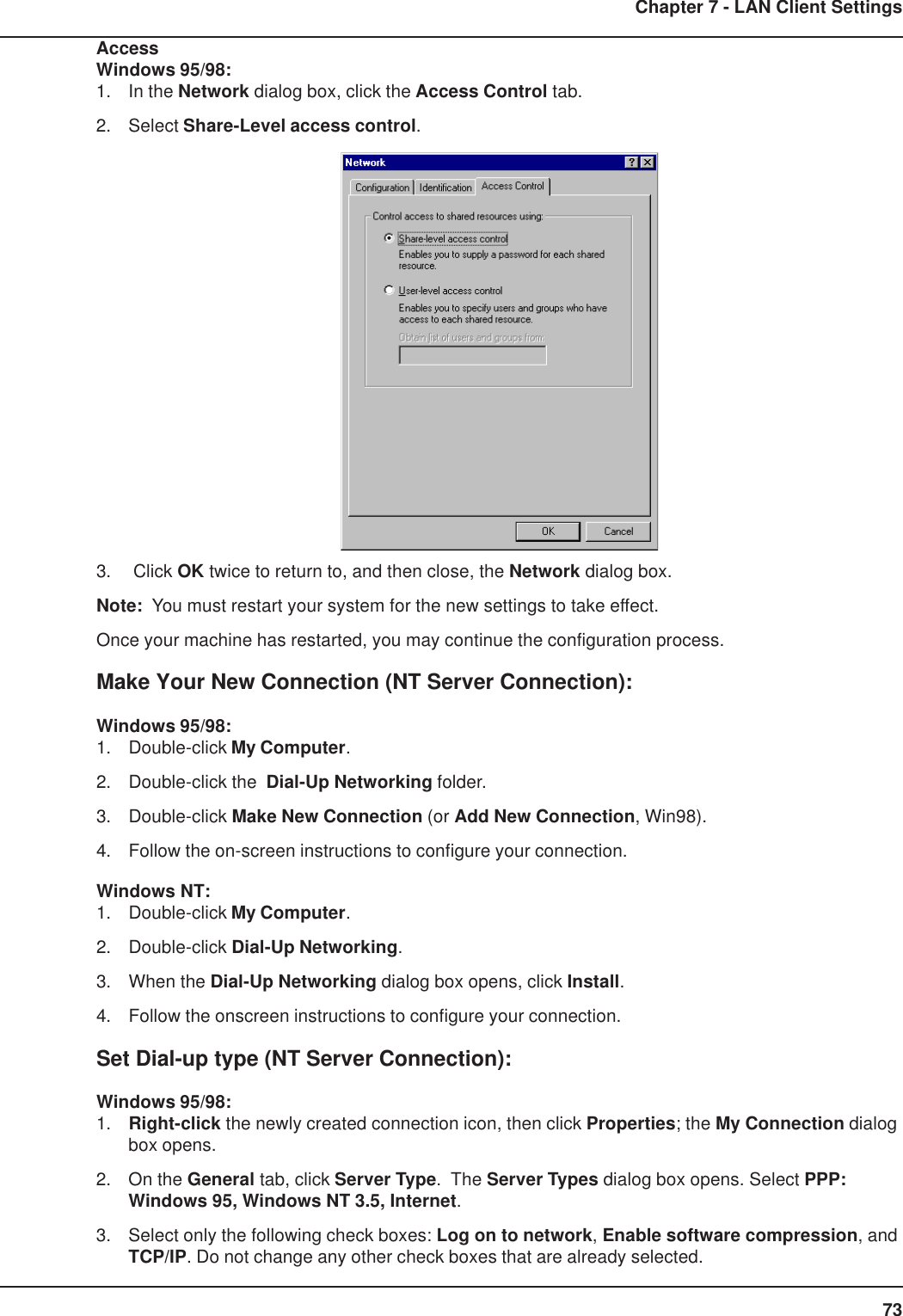
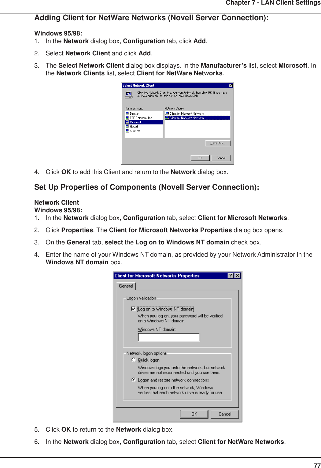
![90Chapter 7 - LAN Client SettingsAdding TCP/IP (Unix Server Connection)Windows 95/98/NT:1. In the Network dialog box, Configuration tab, click Add.2. Select Protocol and click Add.3. The Select Network Protocol dialog box is displayed. In the Manufacturers list [Win95 only],select Microsoft. In the Network Protocols list, select TCP/IP [Win95/98] or TCP/IP Protocol[WinNT only].[Note: Windows NT workstation has no Manufacturers list.] Win95/98 WinNT4. Click OK twice to return to, and then close, the Network dialog box.Set Up Properties of Components (Unix Server Connection)Dial-up AdapterWindows 95/98:1. In the Network dialog box, Configuration tab, select the TCP/IP - Dial-up adapter.2. Click Properties. The TCP/IP Properties dialog box opens.3. Ensure that Obtain an IP Address Automatically is selected. (It’s the default.)4. Click OK to close the TCP/IP Properties dialog box.Note: You must restart your machines to enable the new settings.](https://usermanual.wiki/Multi-Tech-Systems/92U01E04510/User-Guide-155441-Page-90.png)