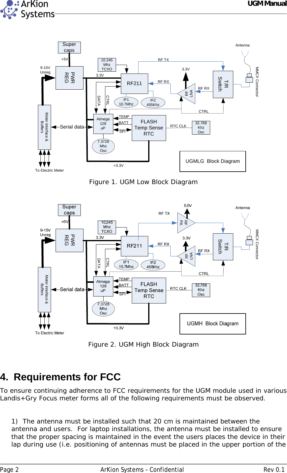
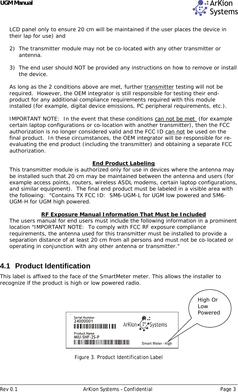
Mueller Systems UGM-L Under Glass Module (UGM) User Manual UGM L Manual Rv0

Mueller Systems, LLC Under Glass Module (UGM) UGM L Manual Rv0

Manual Rv0

  ArKion Systems   Under Glass Module (UGM)  Manual   Document Rev 0.1
 UGM Manual   Page ii  ArKion Systems – Confidential  Rev 0.1  Document Information  Title: UGM Manual Version: 0.1 Created: 12/8/2008  Last Modified On:  12/8/2008 Author:  Technical Lead:   Contributors:    Revision History  Version Date  Author  Comments 0.1 12/03/08 TC  Initial draft, submitted for review 0.2               Reviewers  Reviewed By  Title  Date Reviewed
UGM Manual  Rev 0.1  ArKion Systems – Confidential  Page iii Table of Contents  1. Introduction .............................................................................................. 1 2. Supported Products ................................................................................... 1 3. Product Block Diagram .............................................................................. 1 4. Requirements for FCC ................................................................................ 2 4.1 PRODUCT IDENTIFICATION ............................................................................... 3 4.2 FCC IDENTIFICATION..................................................................................... 4  Table of Figures  FIGURE 1. UGM LOW BLOCK DIAGRAM........................................................................... 2 FIGURE 2. UGM HIGH BLOCK DIAGRAM .......................................................................... 2 FIGURE 3. PRODUCT IDENTIFICATION LABEL ..................................................................... 3 FIGURE 4. FCC LABEL............................................................................................... 4
UGM Manual  Rev 0.1  ArKion Systems – Confidential  Page 1 1. Introduction The ArKion UGM (Under Glass Module) is an ISM band 902 to 928 Mhz frequency hopping transceiver module. There are two radio performance options for this module, a high power module with RF output power between 26dbm and 30dbm and a low power module with RF output power of between 10dbm and 16dbm. The modules are intended to be installed in an off the shelf electric meter with an interface providing power and a serial data connection to the UGM module.   The power supplied by the electric meter is an unregulated 9~15Vdc. The UGM low power module employs a switching regulator to regulate the supply voltage to 5Vdc and then a linear regulator for a local 3.3V supply.  For the high power module, an AC to DC universal switching power supply draws power directly from the AC mains connected to the electric meter. The supply generates a regulated 5V. A linear regulator is used to then create a local 3.3V  The serial port is a logic level asynchronous port with a TX and RX lines. All data is buffered on the UGM module to/from the electric meter. The UGM interrogates the ANSI C.12 register set in off the shelf solid-state electric meters from Landis + Gyr.  It’s main function is to obtain energy consumption, negative consumption, and voltage readings for billing, distribution monitoring, fraud detection, and conservation purposes. Meter reading interval is remotely settable. Information retrieved from the meters registers are temporarily stored within the Smart Meters solid-state memory.  On a specified interval, the Smart Meter will automatically transmit this information to the ArKion AMI server via. other meters or CCOM using the  Radio Frequency (RF) network.  The ArKion AMI server analyzes and archives the readings.    The UGM uses SuperCapacitors to support transmission of power failure messages and to maintain the time of day clock. The Smart Meter does not use any internal batteries eliminating need for field service.   2. Supported Products  UGM high  UGM low Power  Note: High and low power refer to RF output power. low power is approximately +13dbm and high power is +30dbm Max. Other than transmit power the operation of the two radios is identical.  3.  Product Block Diagram  The UGM module design contains 3 basic blocks, a processor & memory block, an RF transceiver block, and for the high power version an RF Power amplifier block. Both of the RF sections are isolated under their own RF shield.
 UGM Manual   Page 2  ArKion Systems – Confidential  Rev 0.1  Atmega128uPMeter interface & BuffersFLASHTemp SenseRTCT/RSwitchPWRREGIF110.7MhzAntenna3.3V3.3V+3.3VSPITEMPRFLNABATT10.245MhzTCXOSupercaps+5VSerial data7.3728 MhzOscRF211 RF RXRF TX32.768KhzOscRTC CLK9-15VUnregRF RXCTRLDATACTRLUGMLG  Block DiagramIF2455KhzMMCX ConnectorTo Electric Meter  Figure 1. UGM Low Block Diagram   Meter interface & BuffersT/RSwitchPWRREGRFLNACTRLDATAMMCX ConnectorRFPA Figure 2. UGM High Block Diagram   4.  Requirements for FCC To ensure continuing adherence to FCC requirements for the UGM module used in various Landis+Gry Focus meter forms all of the following requirements must be observed.    1)  The antenna must be installed such that 20 cm is maintained between the antenna and users.  For laptop installations, the antenna must be installed to ensure that the proper spacing is maintained in the event the users places the device in their lap during use (i.e. positioning of antennas must be placed in the upper portion of the
UGM Manual  Rev 0.1  ArKion Systems – Confidential  Page 3 LCD panel only to ensure 20 cm will be maintained if the user places the device in their lap for use) and  2) The transmitter module may not be co-located with any other transmitter or antenna.   3) The end user should NOT be provided any instructions on how to remove or install the device.    As long as the 2 conditions above are met, further transmitter testing will not be required.  However, the OEM integrator is still responsible for testing their end-product for any additional compliance requirements required with this module installed (for example, digital device emissions, PC peripheral requirements, etc.).  IMPORTANT NOTE:  In the event that these conditions can not be met  (for example certain laptop configurations or co-location with another transmitter), then the FCC authorization is no longer considered valid and the FCC ID can not be used on the final product.  In these circumstances, the OEM integrator will be responsible for re-evaluating the end product (including the transmitter) and obtaining a separate FCC authorization.  End Product Labeling This transmitter module is authorized only for use in devices where the antenna may be installed such that 20 cm may be maintained between the antenna and users (for example access points, routers, wireless ASDL modems, certain laptop configurations, and similar equipment).  The final end product must be labeled in a visible area with the following:  "Contains TX FCC ID:  SM6-UGM-L for UGM low powered and SM6-UGM-H for UGM high powered.    RF Exposure Manual Information That Must be Included The users manual for end users must include the following information in a prominent location "IMPORTANT NOTE:  To comply with FCC RF exposure compliance requirements, the antenna used for this transmitter must be installed to provide a separation distance of at least 20 cm from all persons and must not be co-located or operating in conjunction with any other antenna or transmitter."  4.1 Product Identification This label is affixed to the face of the SmartMeter meter. This allows the installer to recognize if the product is high or low powered radio.      Figure 3. Product Identification Label  High Or Low Powered
 UGM Manual   Page 4  ArKion Systems – Confidential  Rev 0.1 4.2 FCC Identification    Figure 4. FCC Label   This product contains Module FCC ID: SM6-UGM-H This device complies with Part 15 of the FCC Rules. Operation is subject to the following two conditions; (1) this device may not cause harmful interference, and (2) this device must accept any interference received, including interference that may cause undesired operation.

Navigation menu