Motorola Solutions 92FT7118 Mobile 2-Way Radio with WiFi User Manual Installation Manual 1 of 2
Motorola Solutions, Inc. Mobile 2-Way Radio with WiFi Installation Manual 1 of 2
Contents
- 1. Users Guide
- 2. Quick Reference Guide
- 3. Installation Manual 1 of 2
- 4. Installation Manual 2 of 2
- 5. RF Safety Manual
- 6. Manual
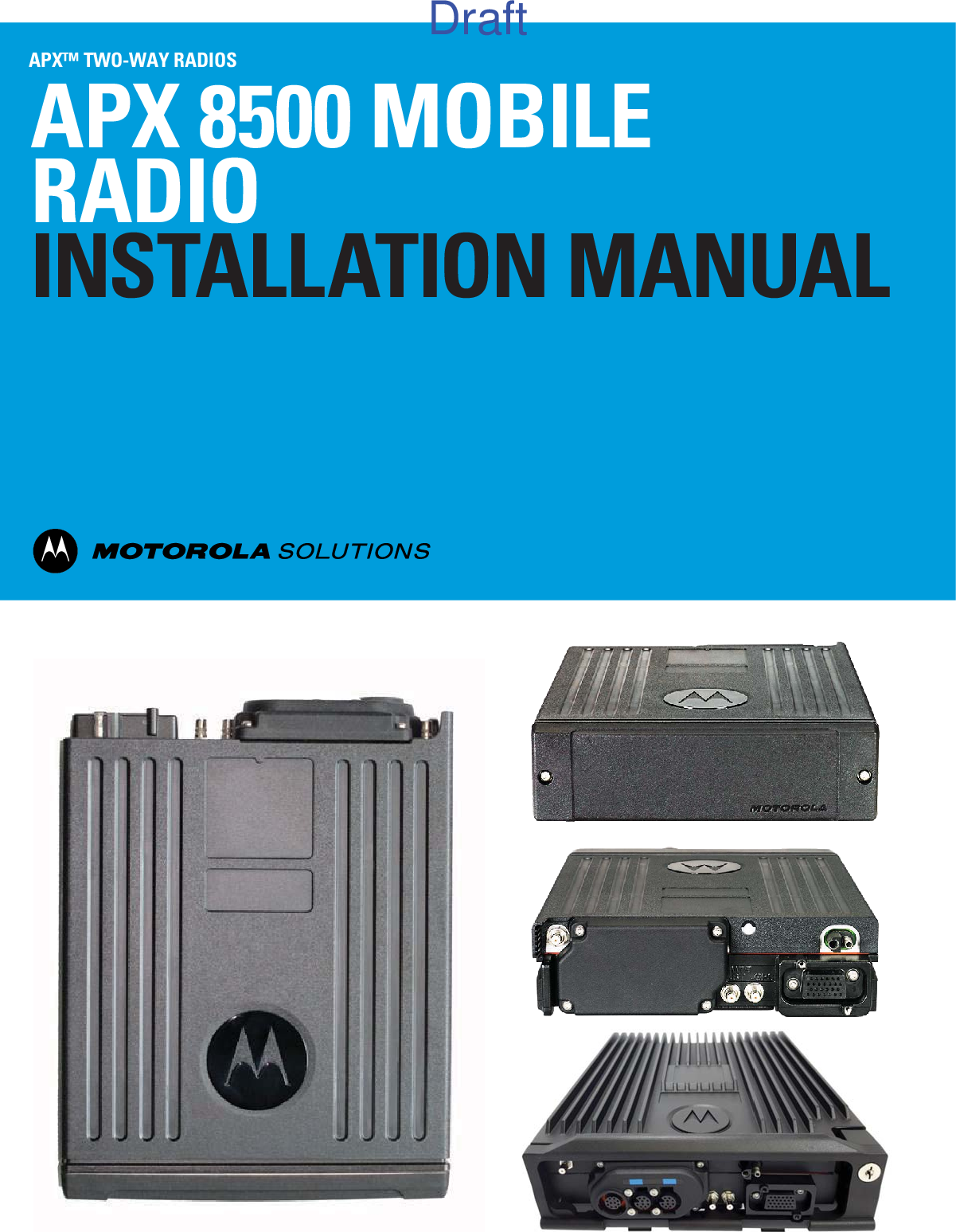
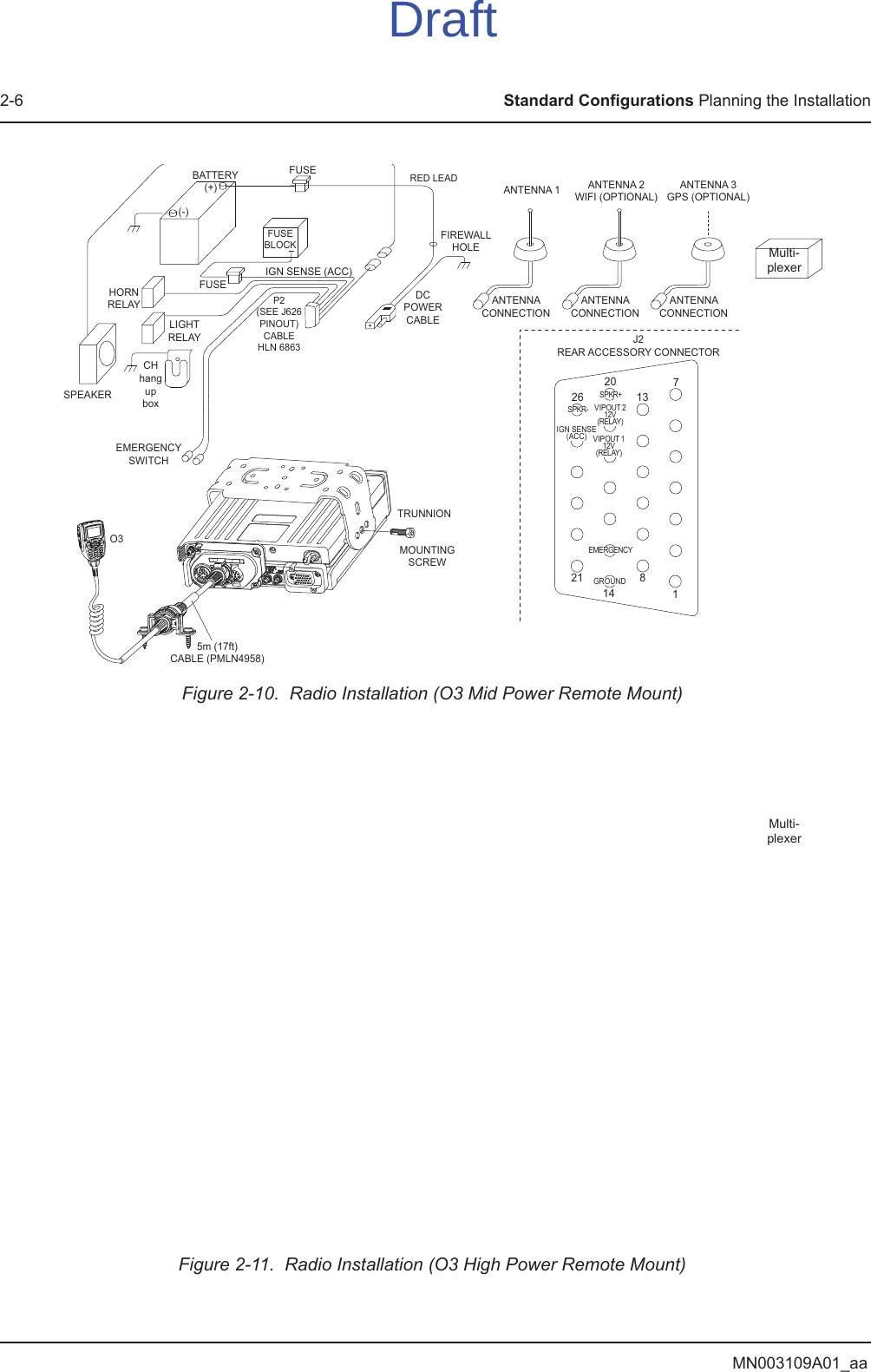
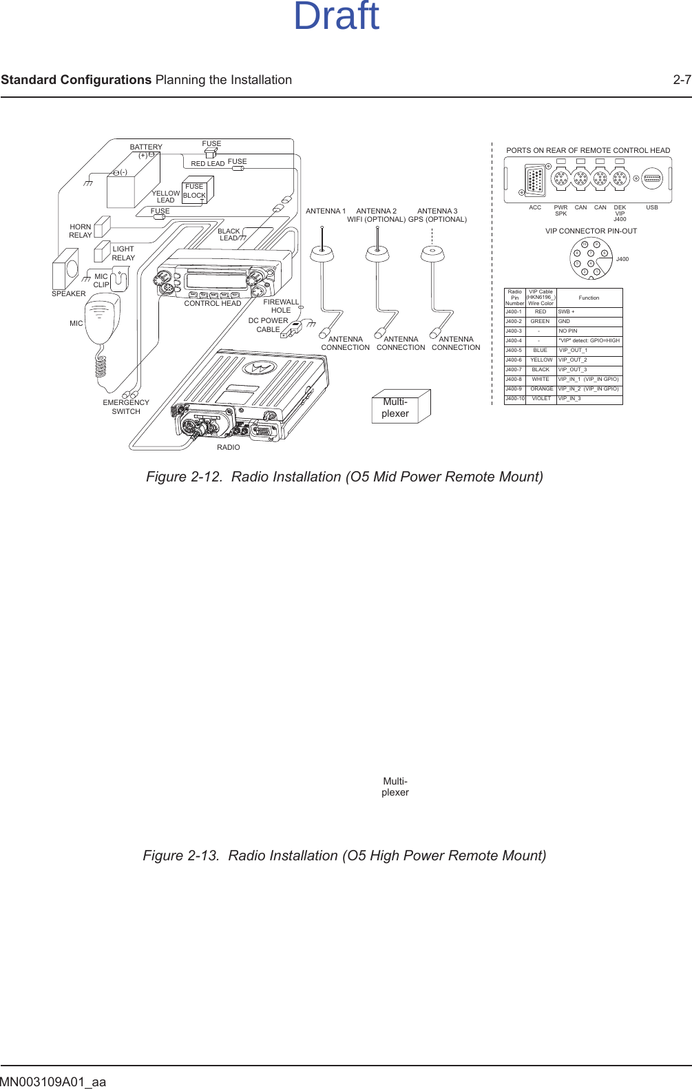
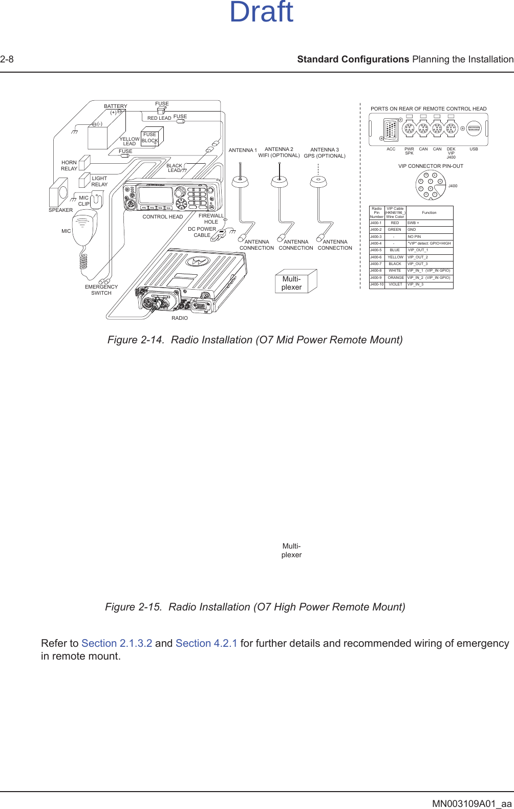
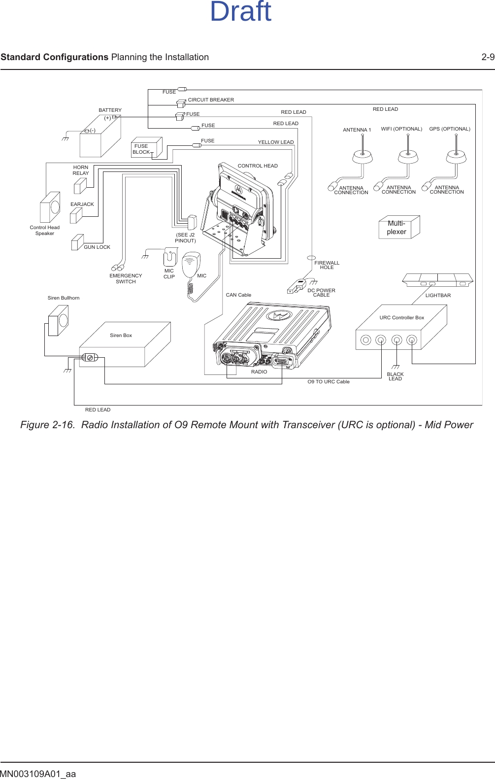
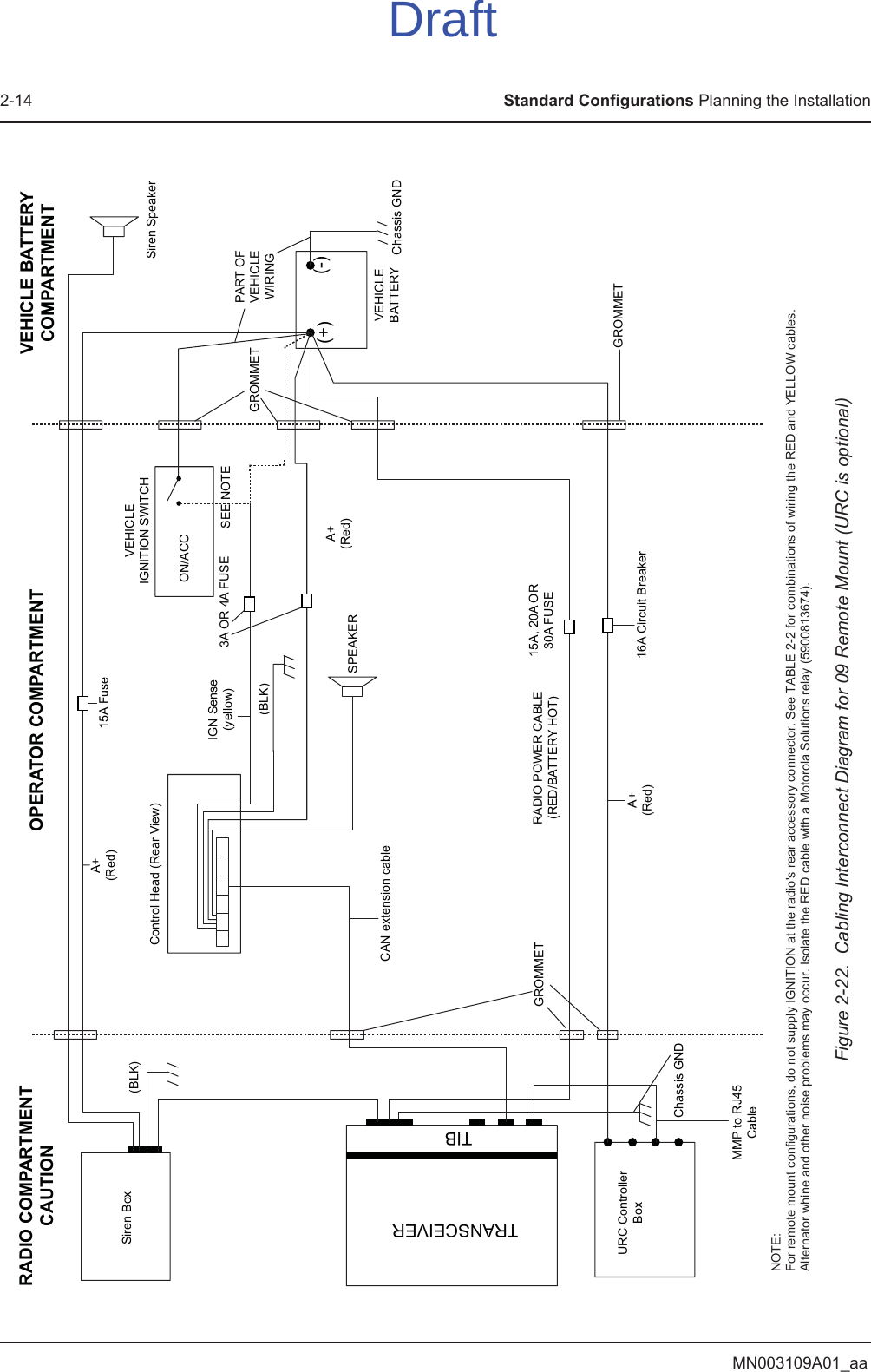
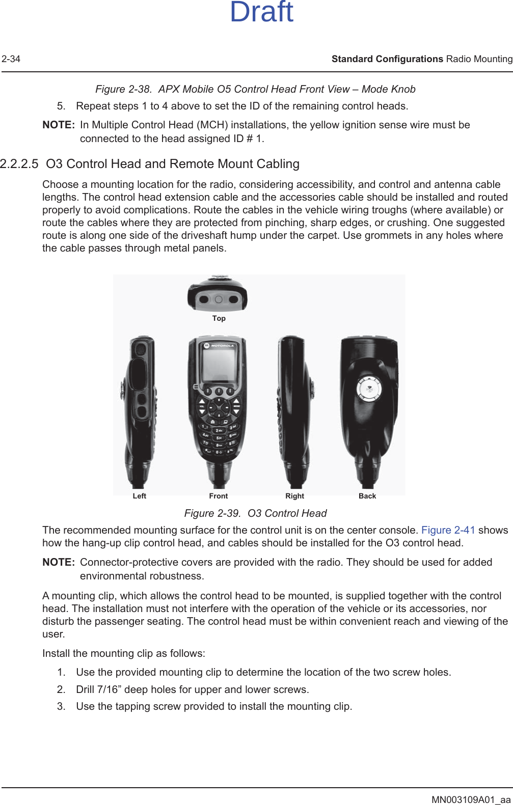
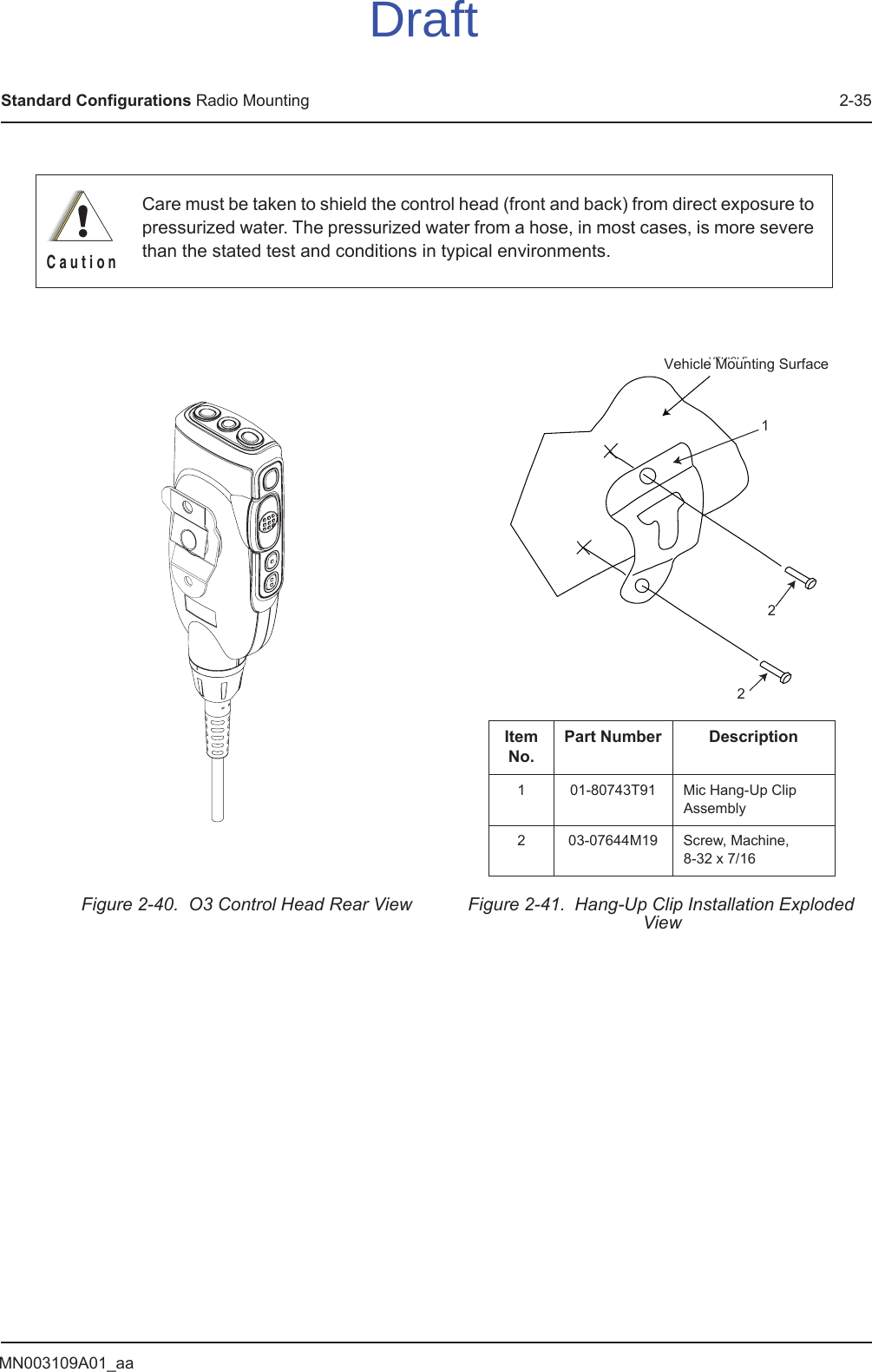
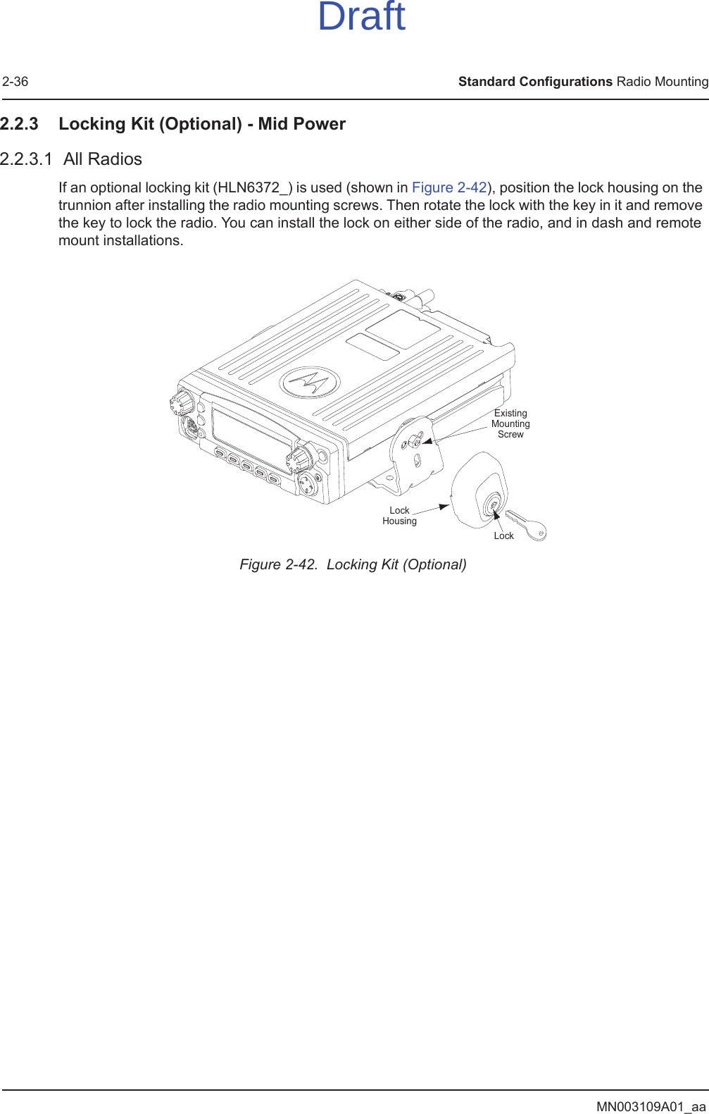
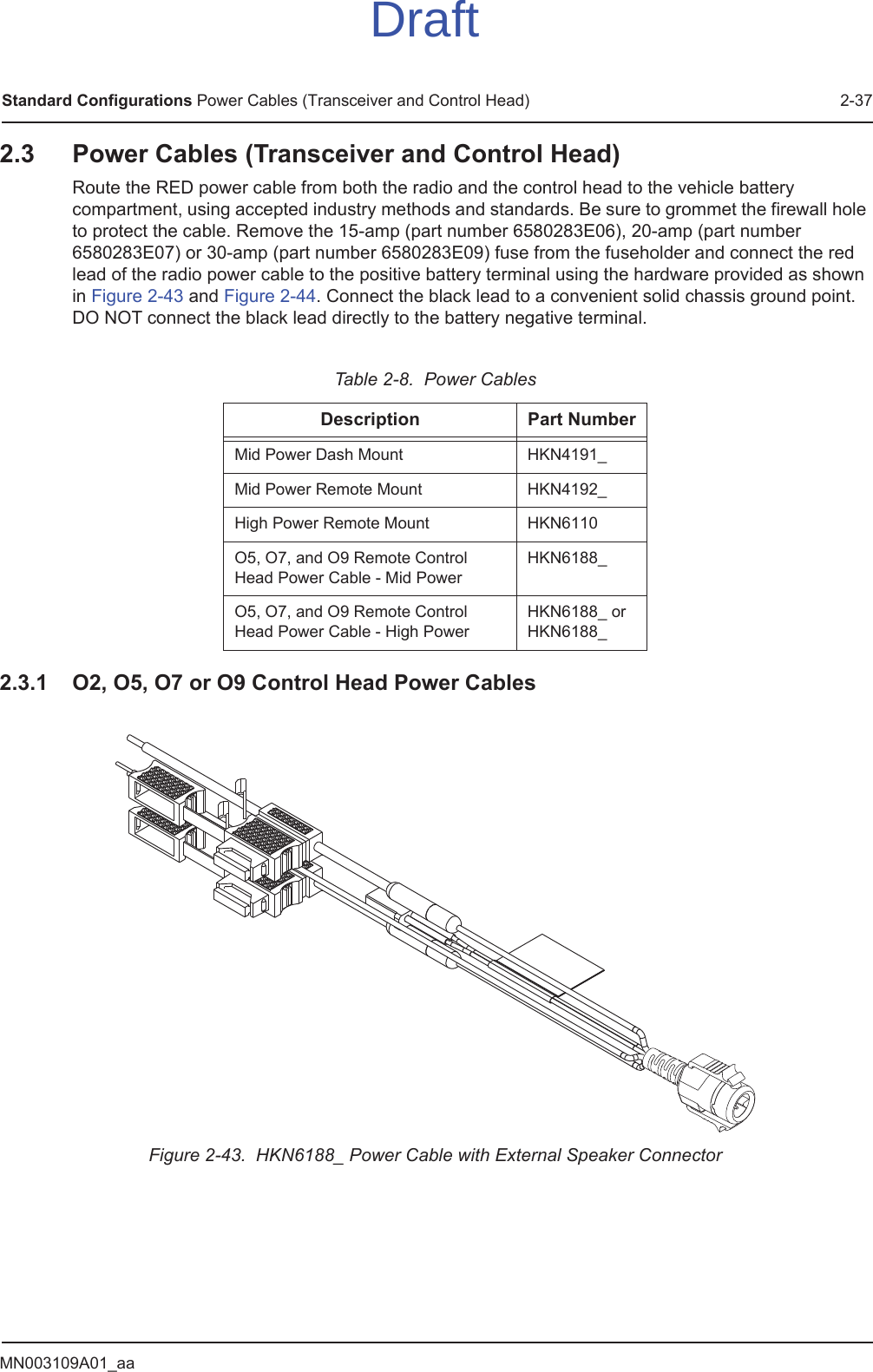
Installation Manual 1 of 2