Motorola Solutions 89FT7629 Access Point/CPE User Manual User Guide Part 4
Motorola Solutions, Inc. Access Point/CPE User Guide Part 4
Contents
- 1. User Guide Part 1
- 2. User Guide Part 2
- 3. User Guide Part 3
- 4. User Guide Part 4
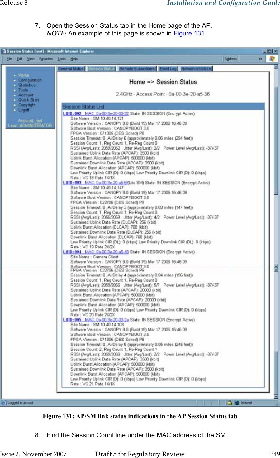
- 5. User Guide Part 5
User Guide Part 4
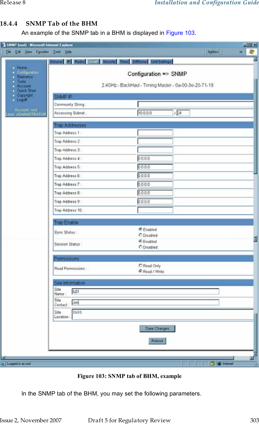
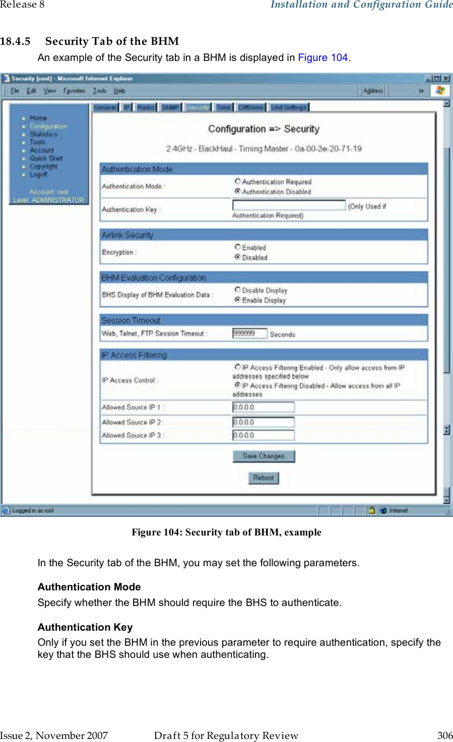
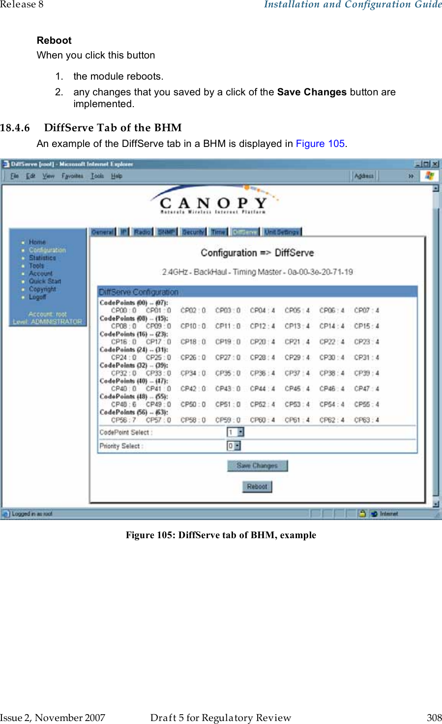


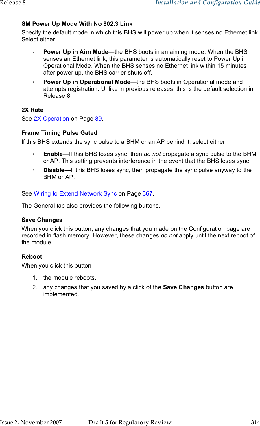
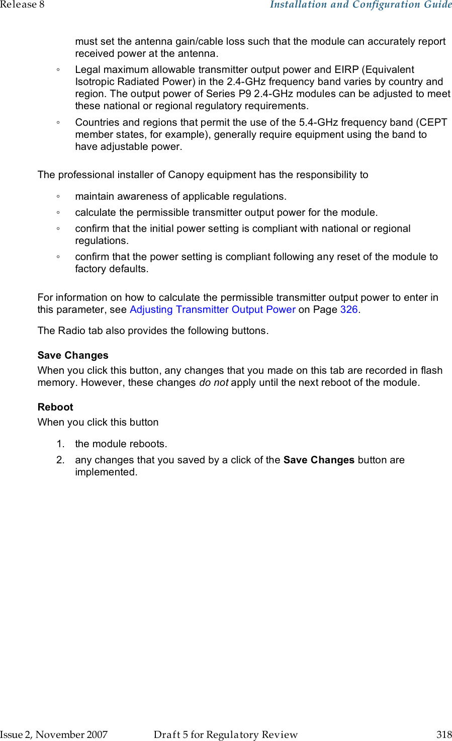
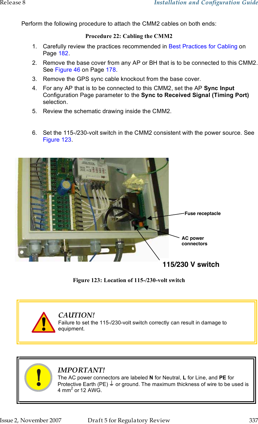
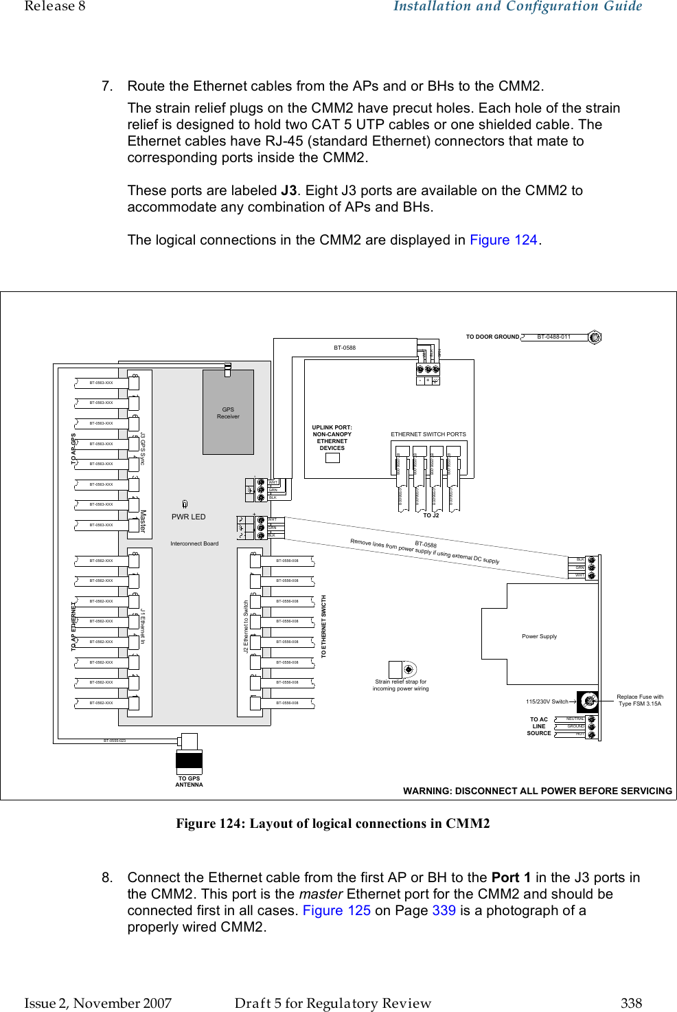
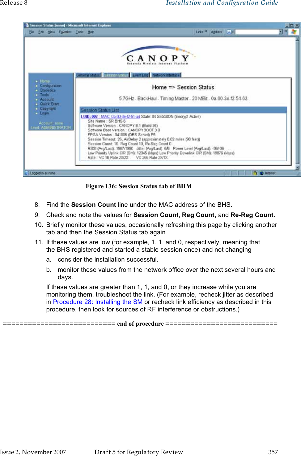
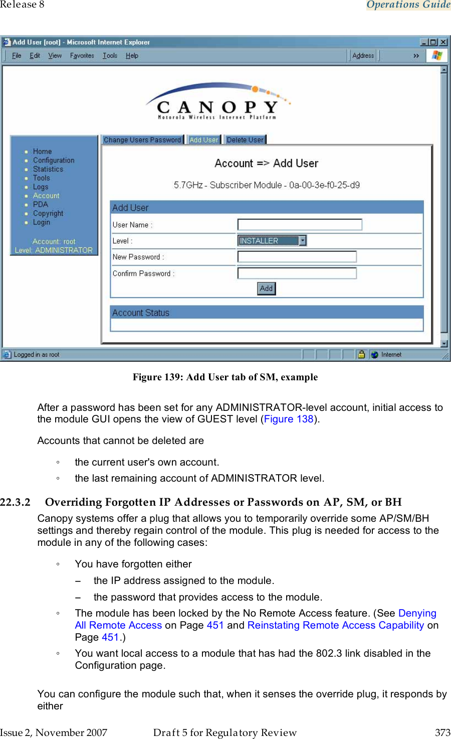
![Release 8 Installation and Configuration Guide Issue 2, November 2007 Draft 5 for Regulatory Review 339 Figure 125: Canopy CMM2, front view 9. Connect the remaining Ethernet cables to the remaining J3 ports. 10. Route the GPS sync (serial) cables from the APs to the CMM2. The GPS sync cables have 6-conductor RJ-11 connectors that mate to corresponding ports inside the CMM2. These ports are labeled J1. Eight J1 ports are available on the CMM2 to accommodate any combination of APs and BHs. 11. Connect the GPS sync cable from the first AP or BH to the Port 1 in the J1 ports in the CMM2. See Figure 125 on Page 339. This port is the master GPS sync port for the CMM2 and should be connected first in all cases. This is necessary to initialize the GPS on the CMM2. 12. Connect the remaining GPS sync cables to the remaining J1 ports. 13. If this CMM2 requires network connection, perform the following steps: a. Route a network cable into the CMM2. b. Connect to the uplink port on the switch. c. Properly ground (connect to Protective Earth [PE] ) the Ethernet cable. The Canopy Surge Suppressor provides proper grounding for this situation. NOTE: Instructions for installing a Canopy Surge Suppressor are provided in Procedure 28 on Page 344.](https://usermanual.wiki/Motorola-Solutions/89FT7629.User-Guide-Part-4/User-Guide-866914-Page-39.png)
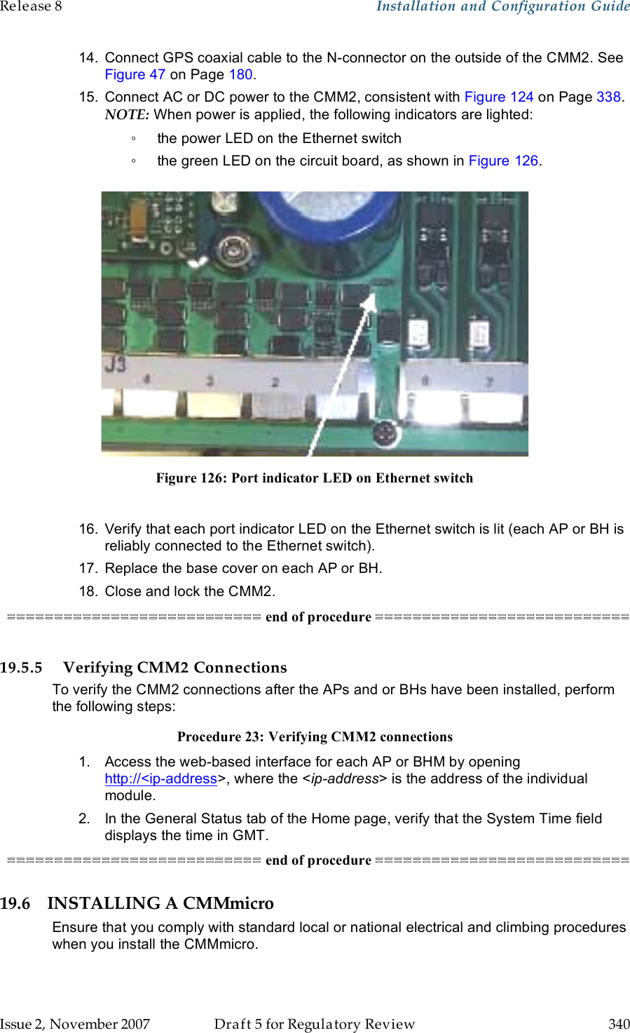
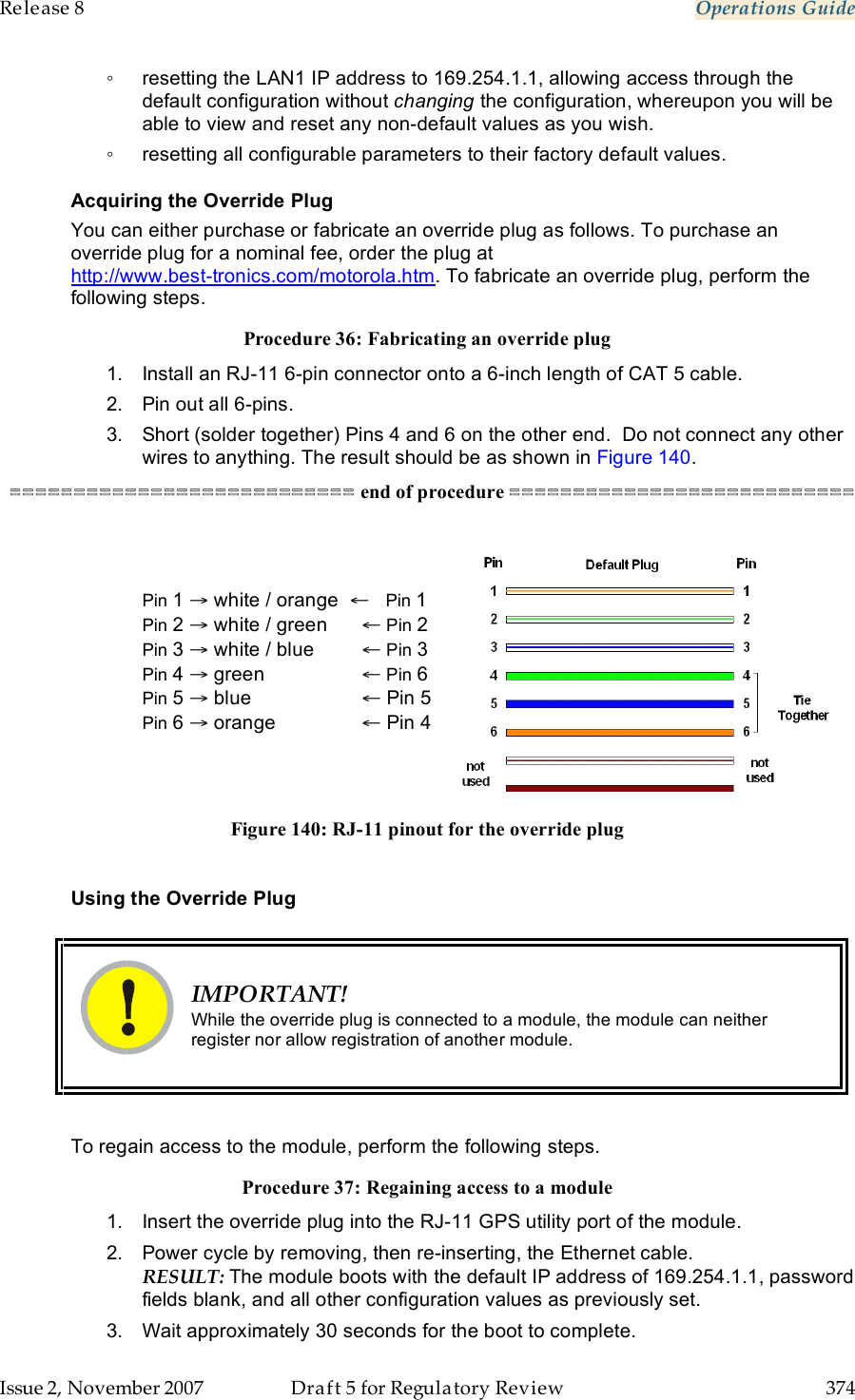
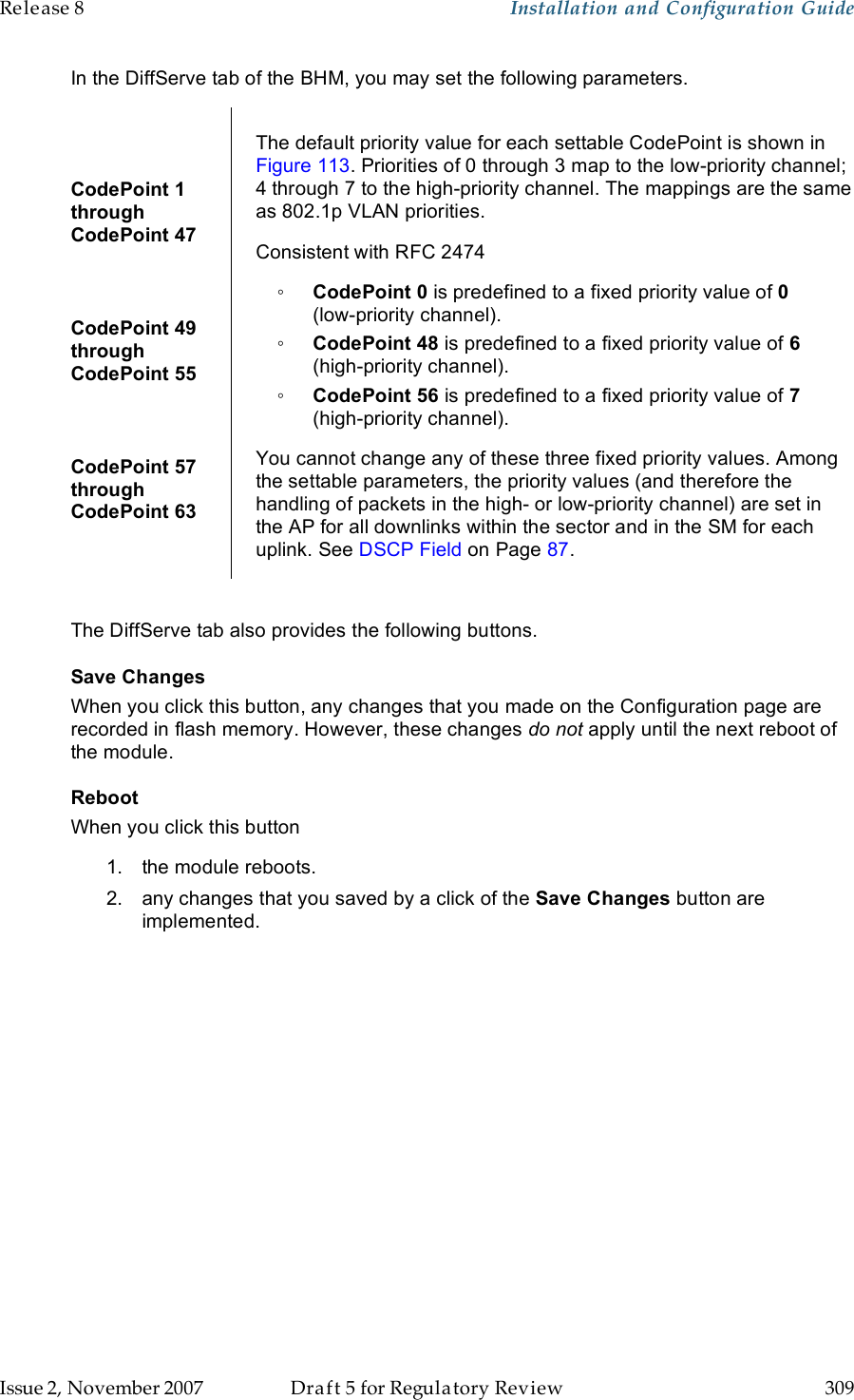
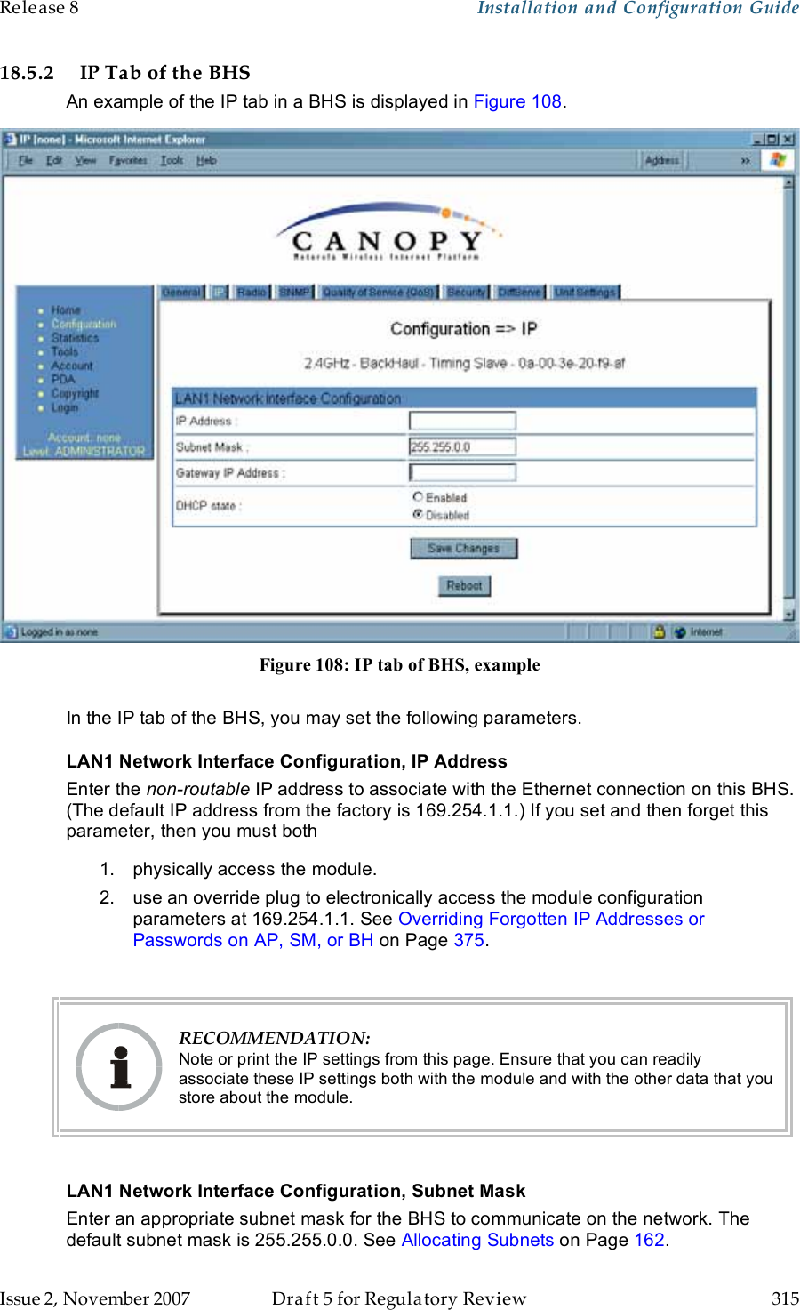
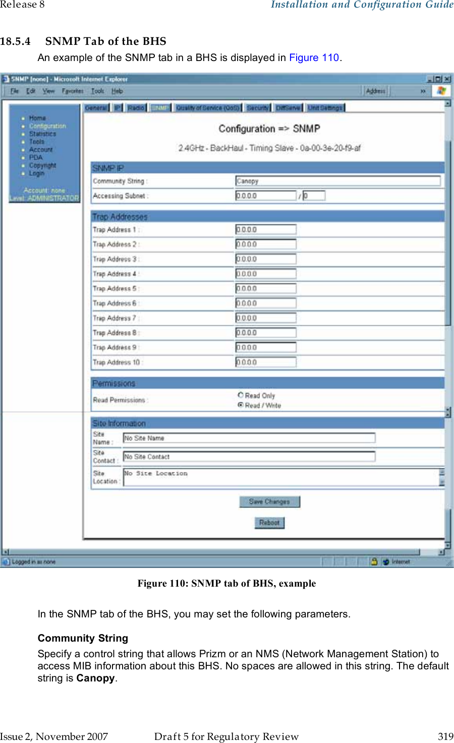
![Release 8 Installation and Configuration Guide Issue 2, November 2007 Draft 5 for Regulatory Review 343 2. Review the schematic drawing inside the CMMmicro and see Figure 70: CMMmicro connections on Page 220. 3. Note that the inserts in the bulkhead connector bushings have precut holes. 4. Remove the hard silicon spacer. 5. Route the Ethernet cables from the APs through the bulkhead connectors to the Ethernet switch inside the CMMmicro. 6. If the BH at this site is a 30/60- or 150/300-Mbps BH a. connect the BH outdoor unit (ODU) to the ODU port of the power indoor unit (PIDU). b. connect the PIDU to an unpowered port of the CMMmicro. If the BH is of another modulation rate, route the Ethernet cables from the BH through the bulkhead connectors to the Ethernet switch in the CMMmicro. 7. If the site has a wired network feed, route the cable into the CMMmicro and connect it to an unpowered port on the switch. 8. Mount a Canopy surge suppressor at a low point of the network feed and connect the surge suppressor to solid ground. 9. On the door label, record the MAC and IP addresses of the CMMmicro and all connected equipment. 10. Consistent with practices in your company, note the above information to add later to the company equipment database. 11. Connect the GPS coax cable from the GPS antenna to the female BNC connector in the CMMmicro. 12. If this CMMmicro requires network connection, perform the following steps: a. Route a network cable into the CMMmicro. b. Connect to the uplink port on the switch. c. Properly ground (connect to Protective Earth [PE] ) the Ethernet cable. The Canopy Surge Suppressor provides proper grounding for this situation. NOTE: Instructions for installing a Canopy Surge Suppressor are provided as part of Procedure 28 on Page 344. 13. Connect the DC power cable to the CMMmicro. 14. Plug the DC converter into an AC receptacle. 15. Verify that the LEDs light. =========================== end of procedure =========================== 19.6.6 Verifying CMMmicro Connections To verify the CMMmicro connections after the APs and or BHs have been installed, perform the following steps. Procedure 27: Verifying CMMmicro connections 1. Access the web-based interface for each AP or BH by opening http://<ip-address>, where the <ip-address> is the address of the individual module. 2. In the Status page, verify that the time is expressed in GMT. 3. In the menu on the left-hand side of the web page, click on GPS Status. 4. Verify that the AP or BH is seeing and tracking satellites. (To generate the timing pulse, the module must track at least 4 satellites.)](https://usermanual.wiki/Motorola-Solutions/89FT7629.User-Guide-Part-4/User-Guide-866914-Page-43.png)