Motorola Solutions 89FT5860 Portable 2-Way Radio User Manual APX 3000 User Guide
Motorola Solutions, Inc. Portable 2-Way Radio APX 3000 User Guide
UserManual.wiki
>
Motorola Solutions
>
89FT5860 User Manual
>
User Manual
Contents
1.
RF Safety Manual
2.
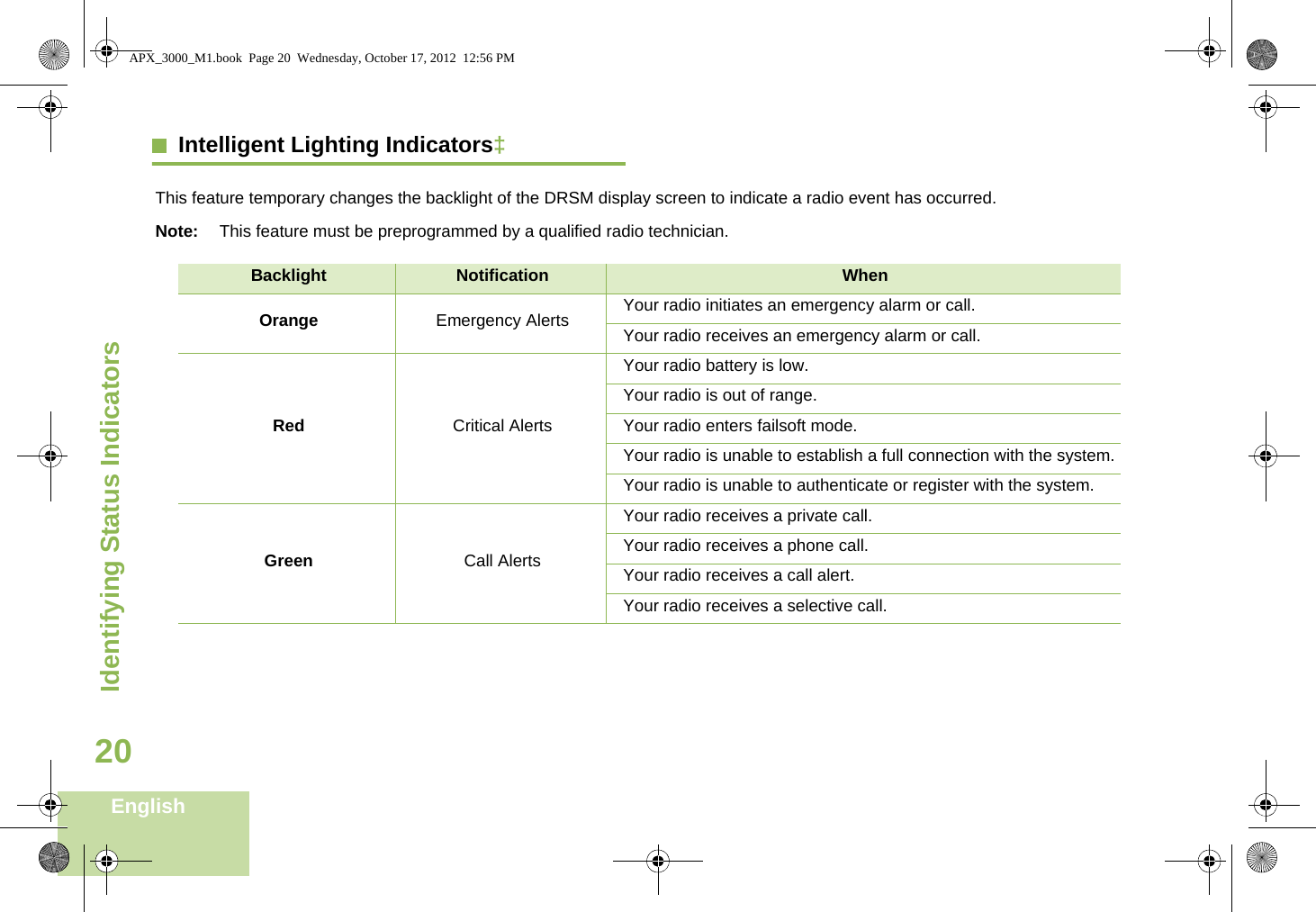
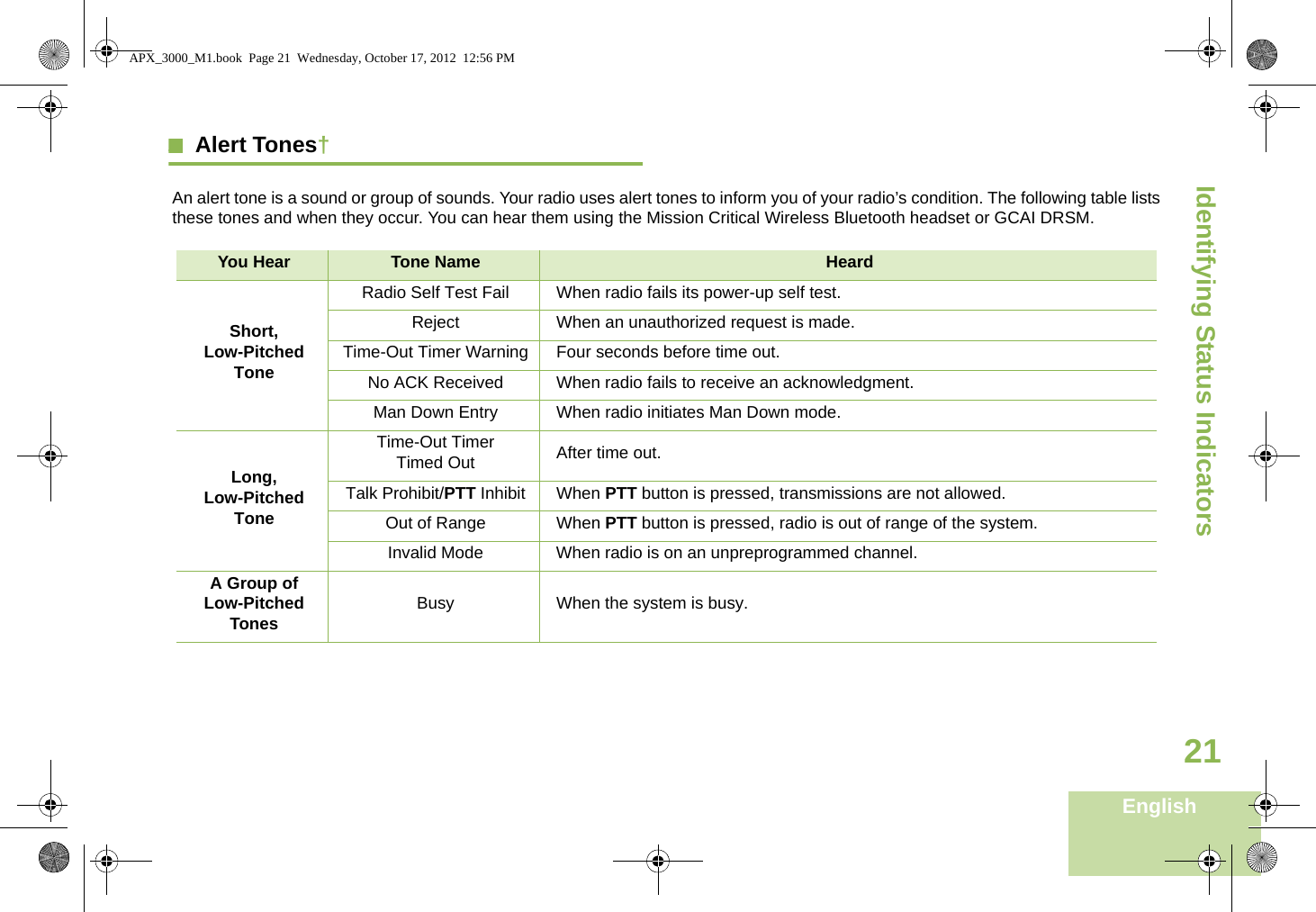
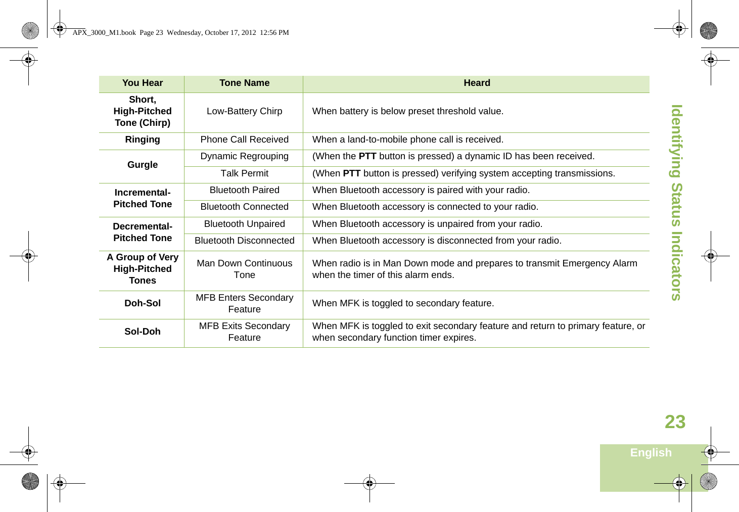
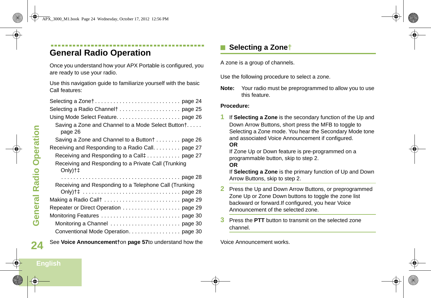
User Manual
3.
RF Safety Guide
4.
Quick Start Guide
5.
Replacement Drawing for Quick Start Guide
User Manual
Navigation menu
Upload a User Manual
Namespaces
Wiki Guide
HTML
PDF
Info
Views
User Manual
Discussion / Help
Navigation