Motorola Solutions 89FT3837 2-way portable VHF radio (MURS) User Manual BRUS display
Motorola Solutions, Inc. 2-way portable VHF radio (MURS) BRUS display
UserManual.wiki
>
Motorola Solutions
>
89FT3837 User Manual
>
User Manual
Contents
1.
User Manual Safety
2.
User Manual
User Manual
Navigation menu
Upload a User Manual
Namespaces
Wiki Guide
HTML
PDF
Info
Views
User Manual
Discussion / Help
Navigation
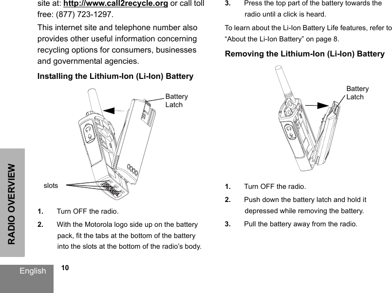
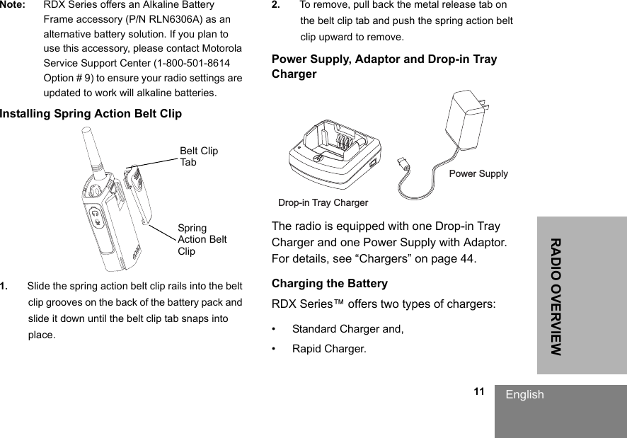
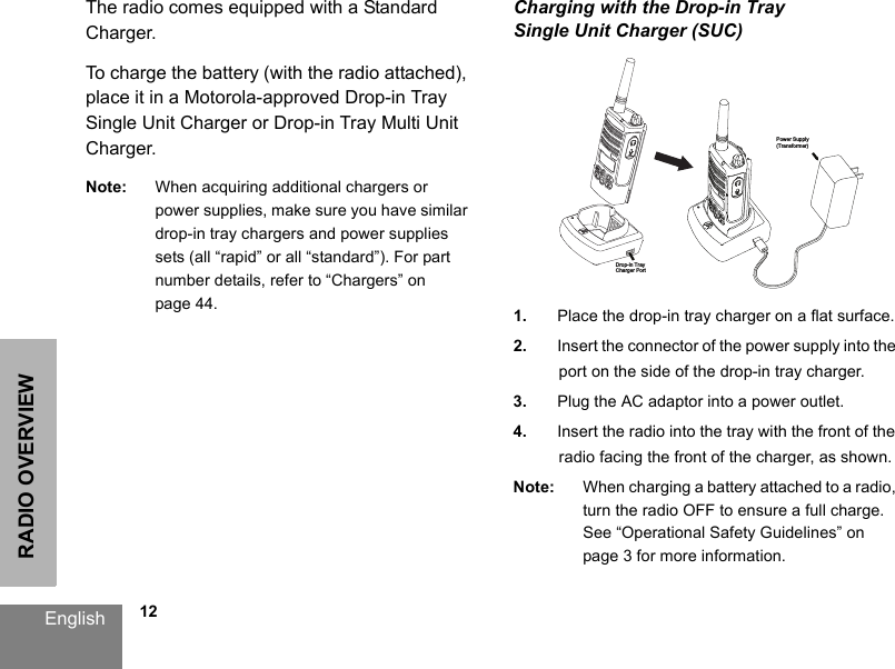
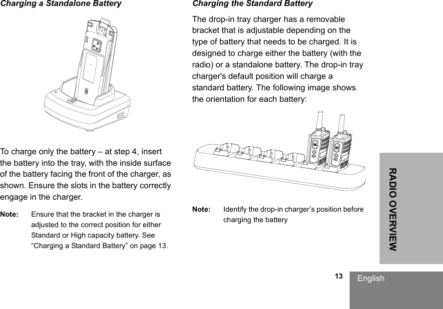
![9RADIO OVERVIEWEnglishwill last. For example, a battery which is overcharged and discharged 100% several times a day, lasts fewer cycles than a battery that receives less of an overcharge and is discharged to 50% per day. Further, a battery which receives minimal overcharging and averages only 25% discharge, lasts even longer.Motorola batteries are designed specifically to be used with a Motorola charger and vice versa. Charging in non-Motorola equipment may lead to battery damage and void the battery warranty. The battery should be at about 77°F (25°C) (room temperature), whenever possible. Charging a cold battery (below 50° F [10°C]) may result in leakage of electrolyte and ultimately in failure of the battery. Charging a hot battery (above 95°F [35°C]) results in reduced discharge capacity, affecting the performance of the radio. Motorola rapid-rate battery chargers contain a temperature-sensing circuit to ensure that batteries are charged within the temperature limits stated above. Battery Recycling and DisposalLi-Ion rechargeable batteries can be recycled. However, recycling facilities may not be available in all areas. Under various U.S. state laws and the laws of several other countries, batteries must be recycled and cannot be disposed of in landfills or incinerators. Contact your local waste management agency for specific requirements and information in your area. Motorola fully endorses and encourages the recycling of Li-Ion batteries. In the U.S. and Canada, Motorola participates in the nationwide Rechargeable Battery Recycling Corporation (RBRC) program for Li-Ion battery collection and recycling. Many retailers and dealers participate in this program. For the location of the drop-off facility closest to you, access RBRC's Internet web](https://usermanual.wiki/Motorola-Solutions/89FT3837.User-Manual/User-Guide-3054649-Page-13.png)