Motorola Mobility USA-AL200-001 Cable Modem User Manual
Motorola Mobility LLC Cable Modem
UserManual.wiki
>
Motorola Mobility
>
USA AL200 001 User Manual
Users Manaual
Navigation menu
Upload a User Manual
Namespaces
Wiki Guide
HTML
PDF
Info
Views
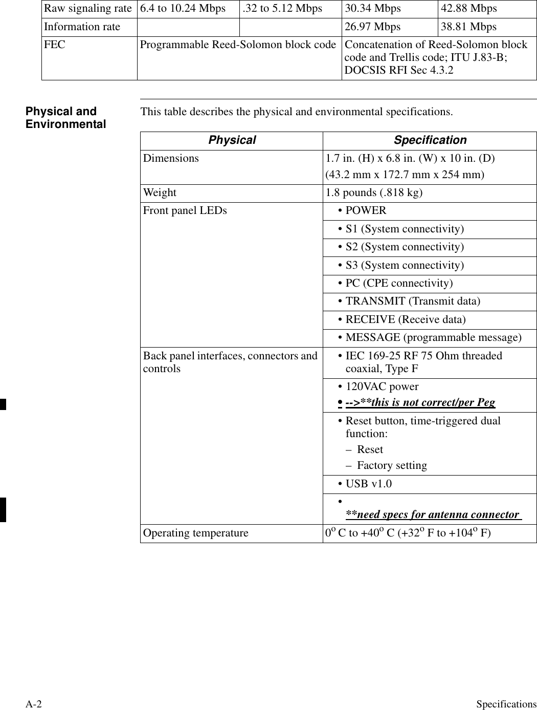
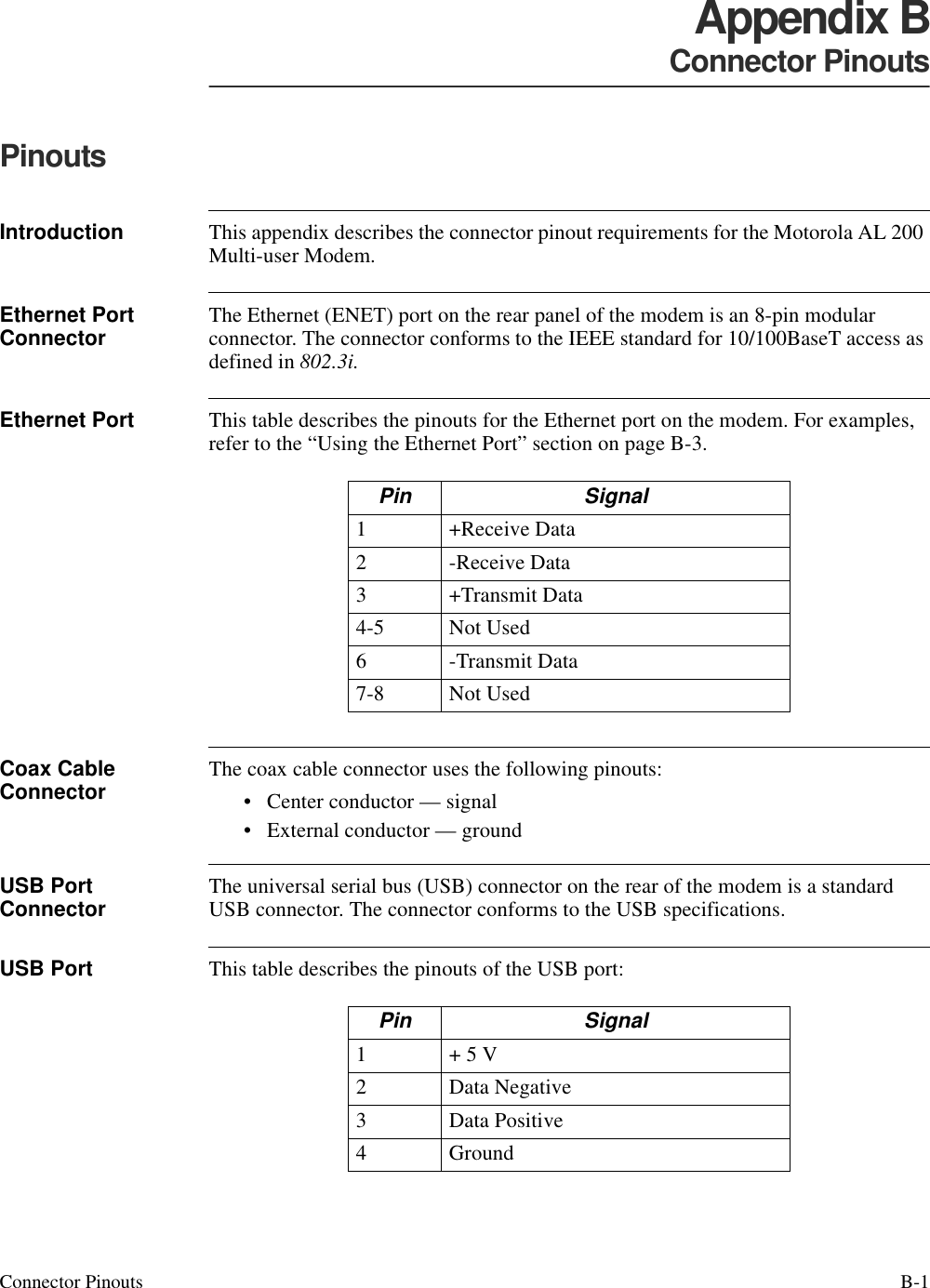
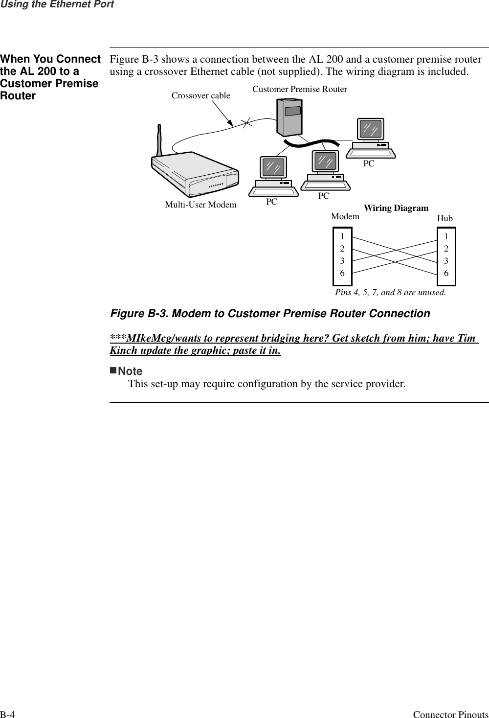
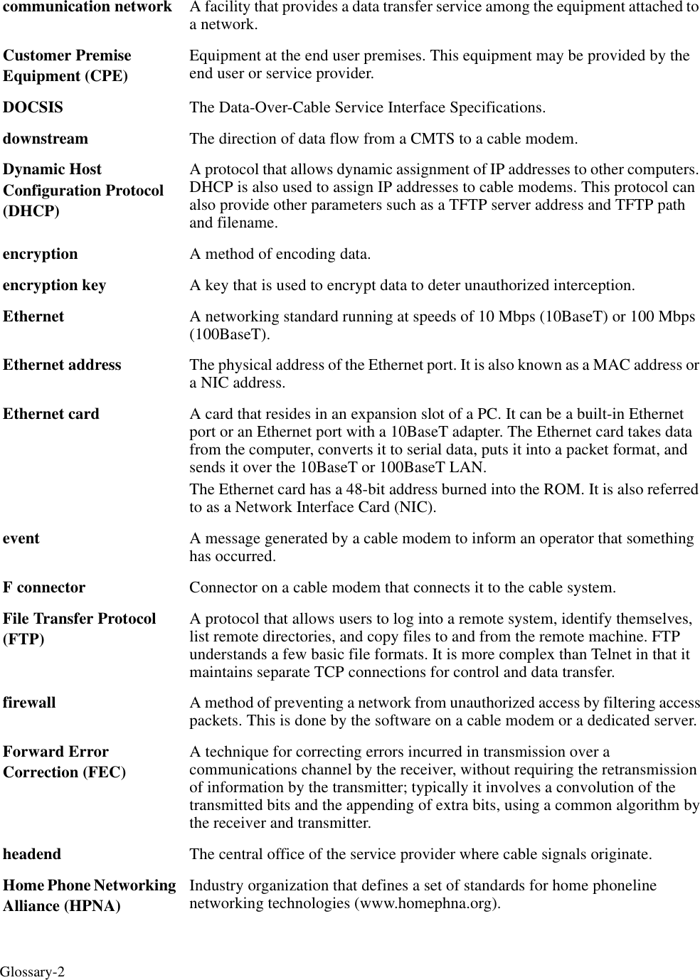
User Manual
Discussion / Help
Navigation