Motorola Mobility T6NE1 Mobile Satellite Transceiver User Manual Sample Cover Page for User s Manual Ex
Motorola Mobility LLC Mobile Satellite Transceiver Sample Cover Page for User s Manual Ex
Contents
- 1. Motorola Exhibit 7 Users Manual
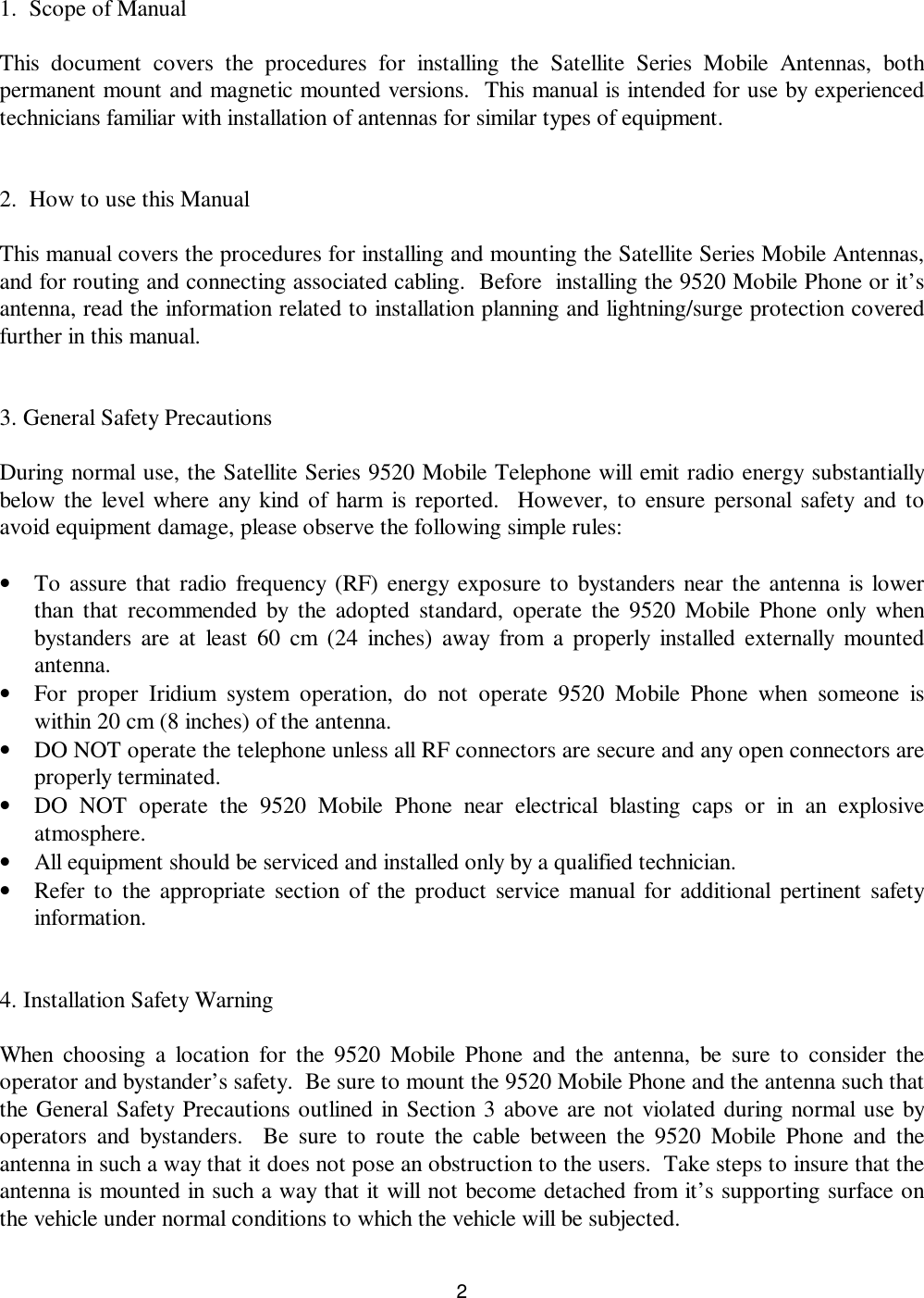
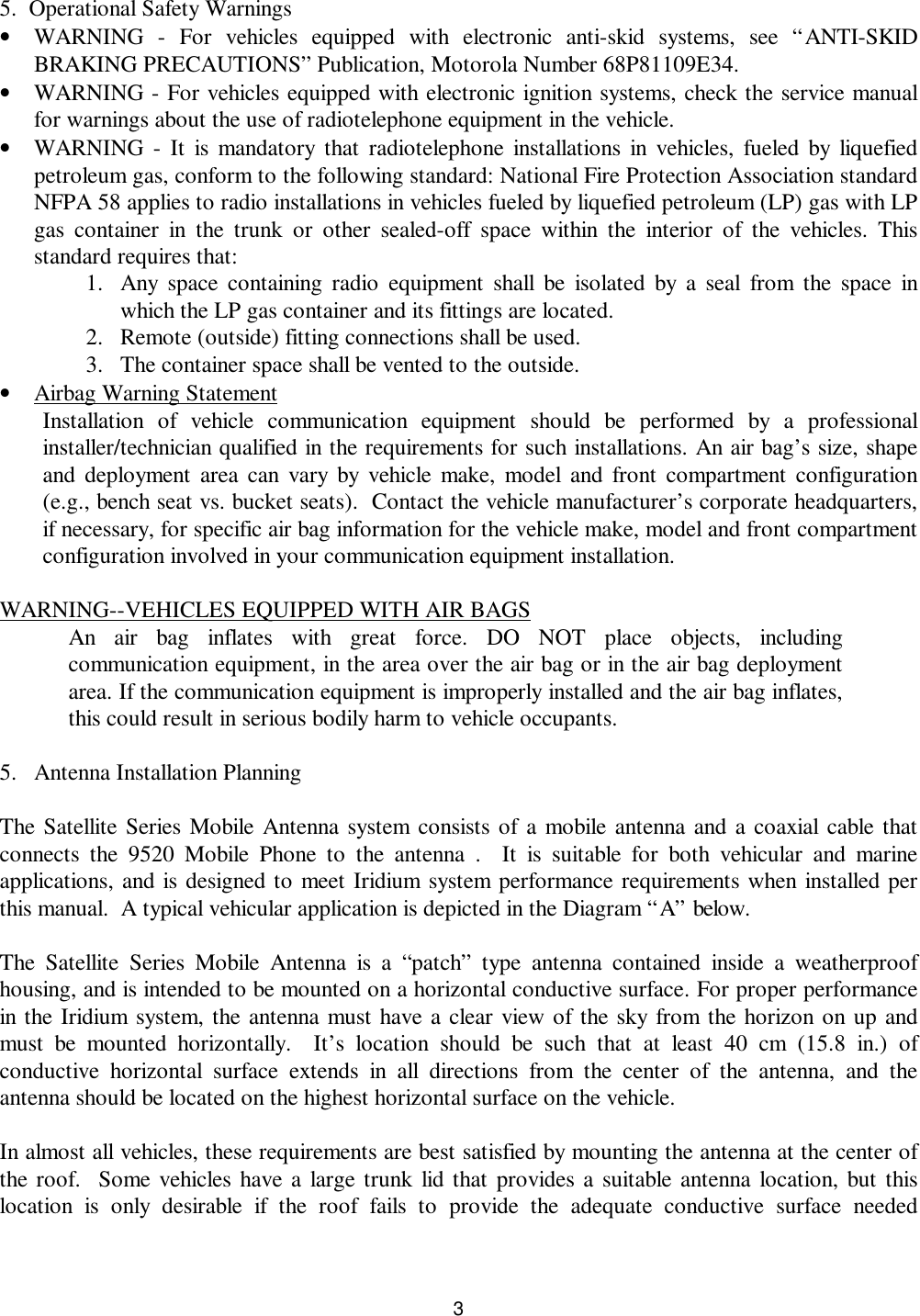
- 2. Motorola Satellite Series Mobile Accessory Antenna Installation Guideline
- 3. Motorola Satellite Series Fixed Site Accessory Antenna Installation Guideline
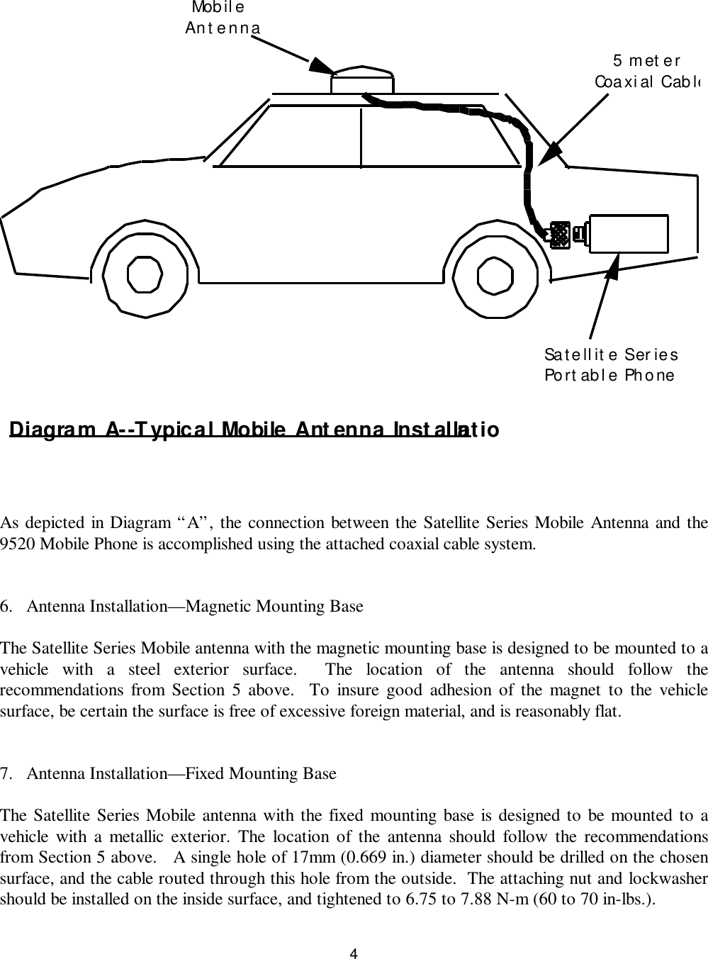
Motorola Satellite Series Mobile Accessory Antenna Installation Guideline