MilDef Crete RW11 Notebook Computer User Manual
MilDef Crete Inc. Notebook Computer Users Manual
UserManual.wiki
>
MilDef Crete
>
RW11 User Manual
Users Manual
Navigation menu
Upload a User Manual
Namespaces
Wiki Guide
HTML
PDF
Info
Views
User Manual
Discussion / Help
Navigation
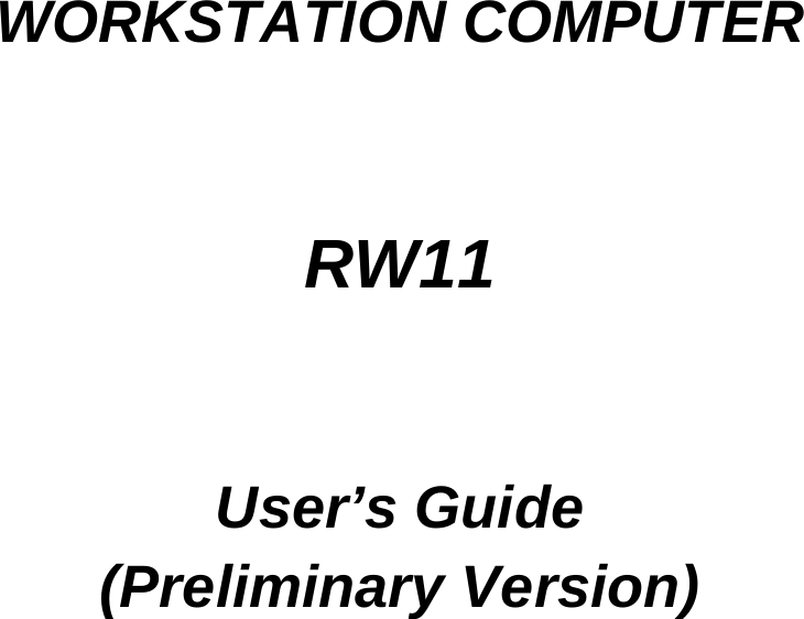


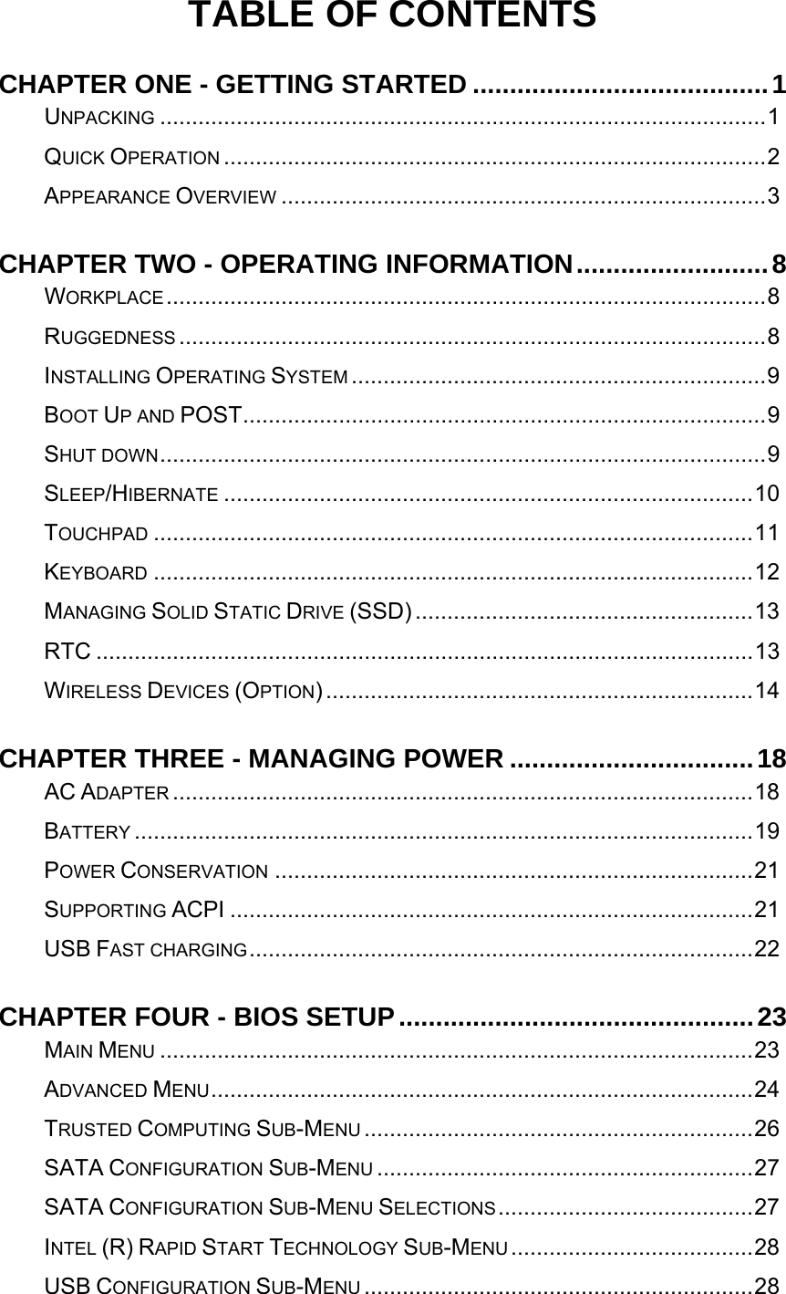

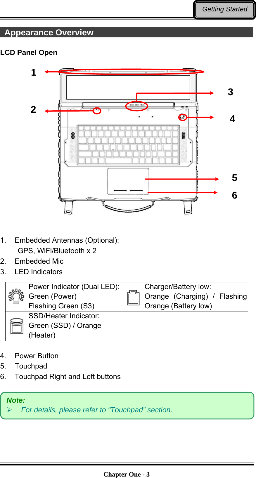
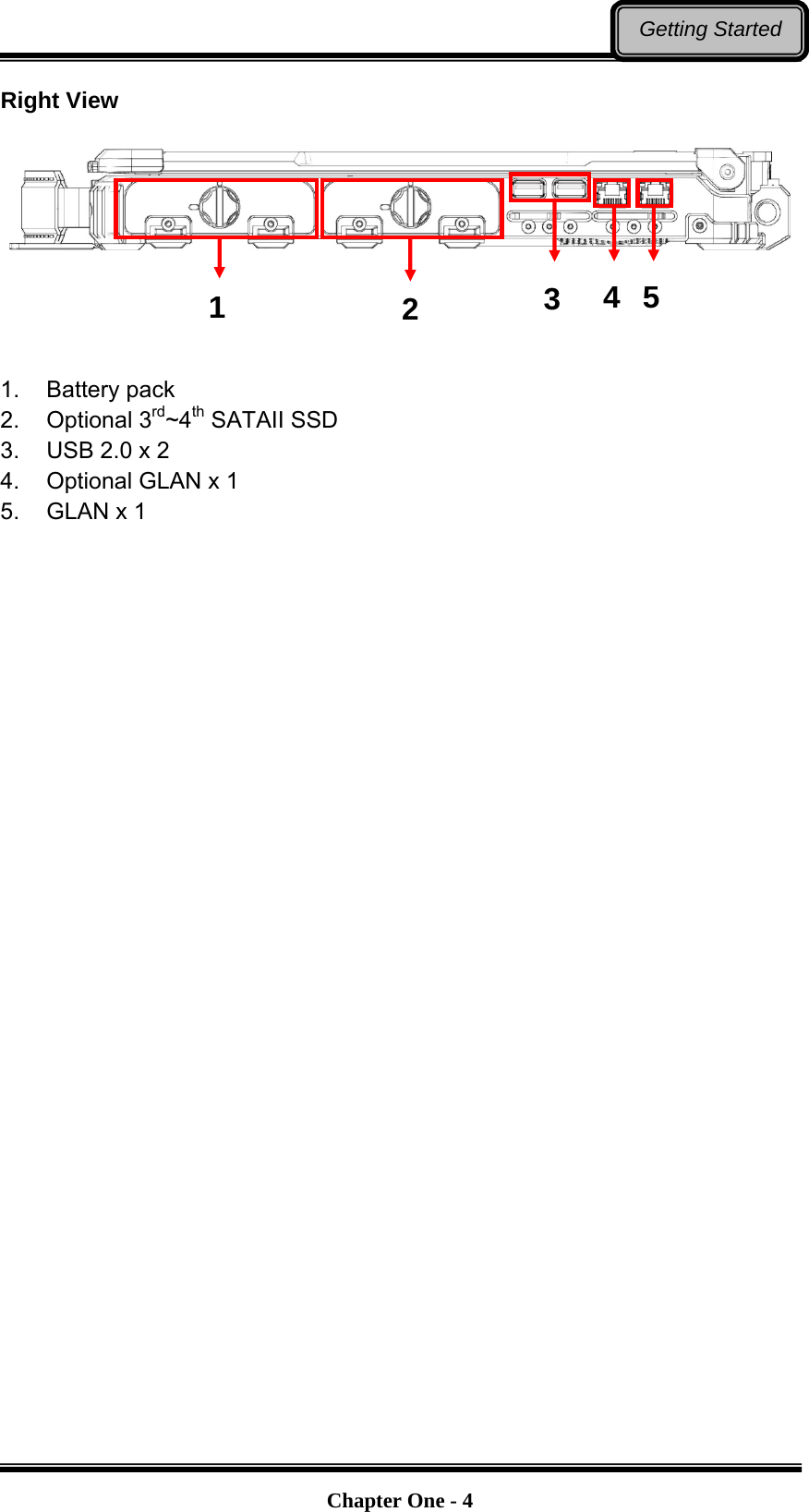
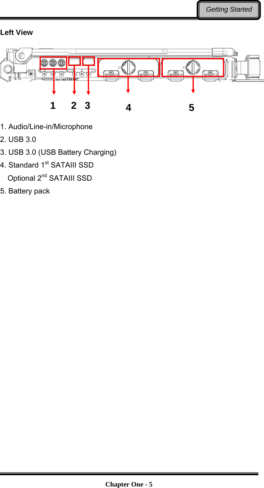
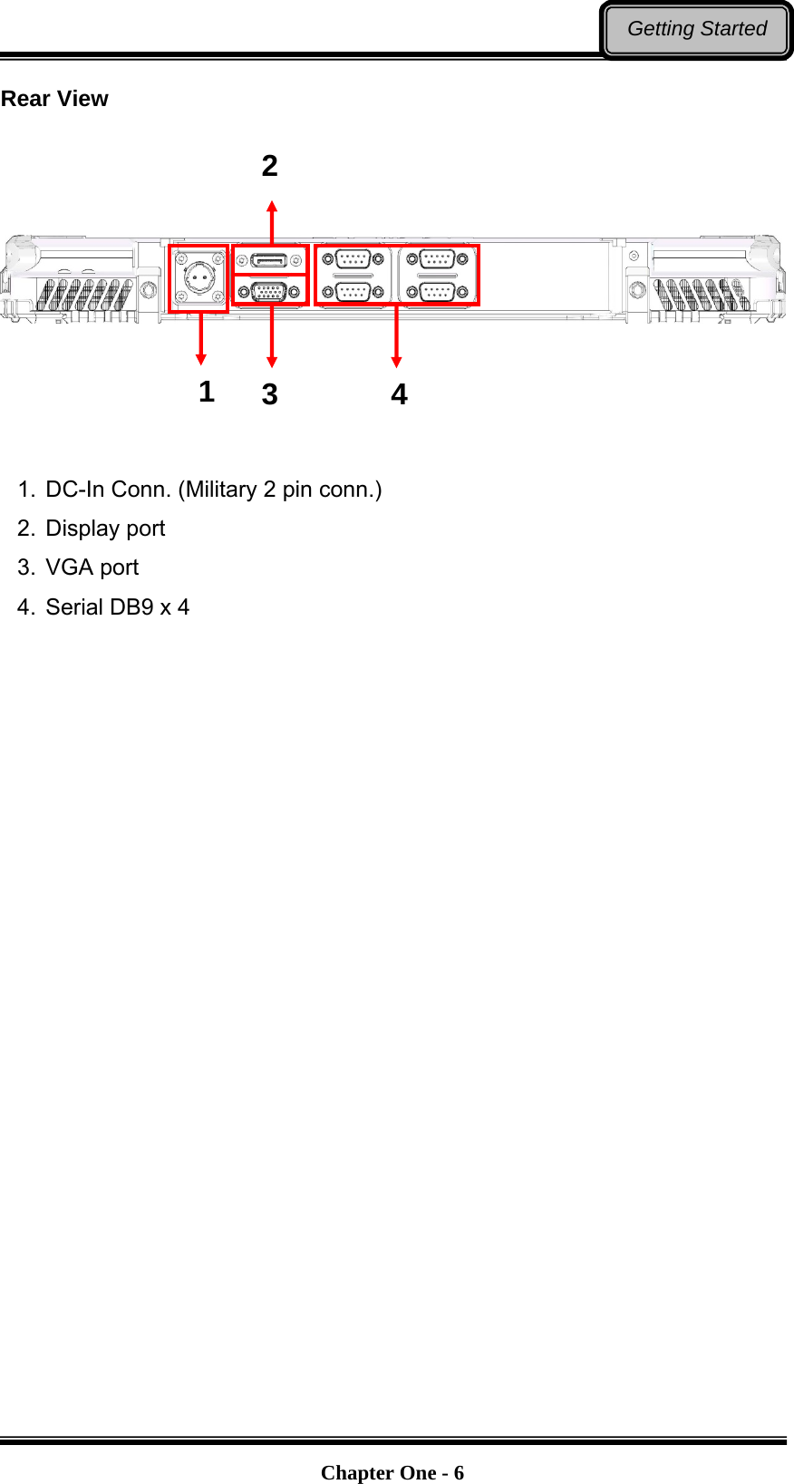
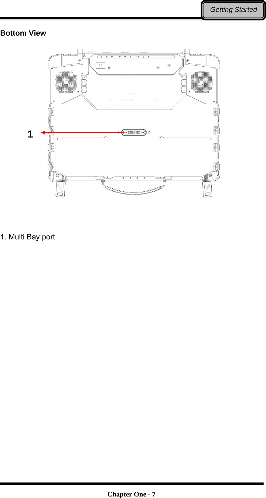
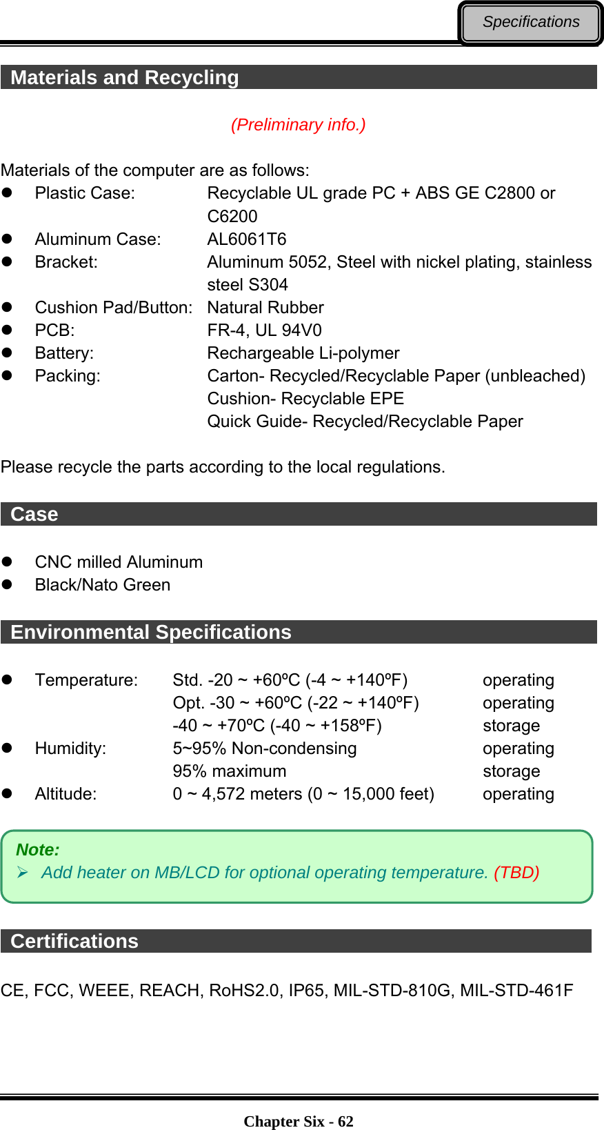
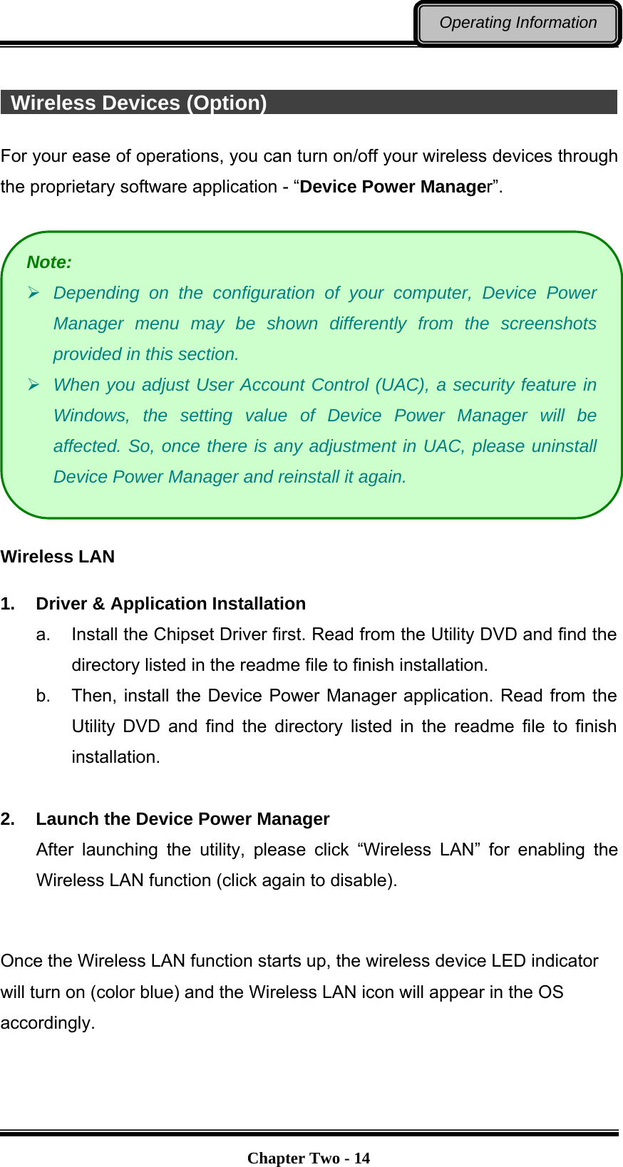
![Chapter Two - 11Operating Information Touchpad The touchpad can be either a multi-touch capacitive type or a single resistive type. It can be enabled/disabled by pressing [Fn] + [F12], and a disable icon will be shown on system tray when it is disabled. For usage details, please see the following table. No. Item Description 1. Touchpad For functions like click, scroll, and swipe 2. Left-click button Similar to left button of mouse 3. Right-click button Similar to right button of mouse Note: For capacitive multi-touch type, please install the touchpad driver for complete functions. Without installing the driver, you can still use single-touch functions, but the functions of multi-touch and touchpad icons on system tray are not available. In addition, if the driver is not installed, the touchpad disable status will not be remembered after S3/S4/reboot/turn off. 1 2 3](https://usermanual.wiki/MilDef-Crete/RW11/User-Guide-2941065-Page-24.png)
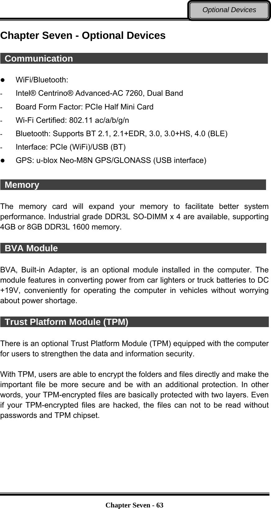
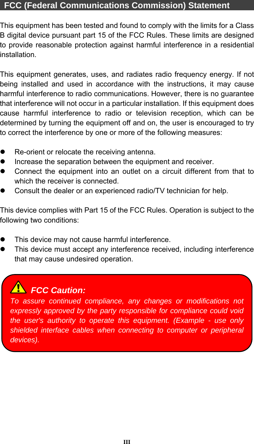
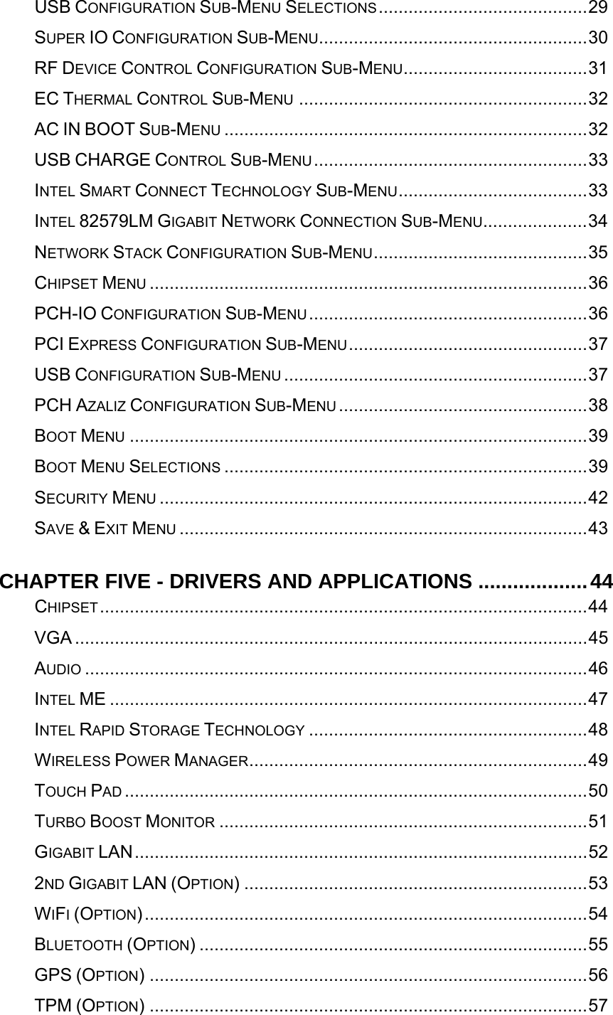
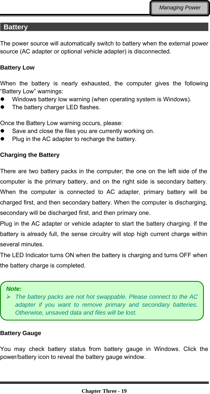
![Chapter Two - 12Operating Information Keyboard The keyboard is functionally equivalent to a full size desktop keyboard. A sample layout is shown as below. Function Key Combinations Key Description [Fn] + [F3] Decrease LCD brightness [Fn] + [F4] Increase LCD brightness [Fn] + [F5] Mute [Fn] + [F6] Volume down [Fn] + [F7] Volume up [Fn] + [F9] Decrease keyboard backlight [Fn] + [F10] Increase keyboard backlight [Fn] + [F12] Touchpad lock](https://usermanual.wiki/MilDef-Crete/RW11/User-Guide-2941065-Page-25.png)
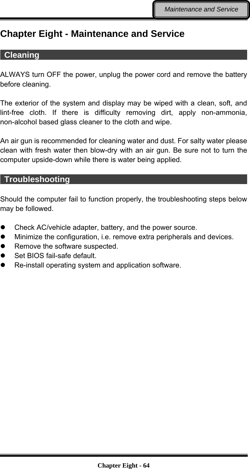
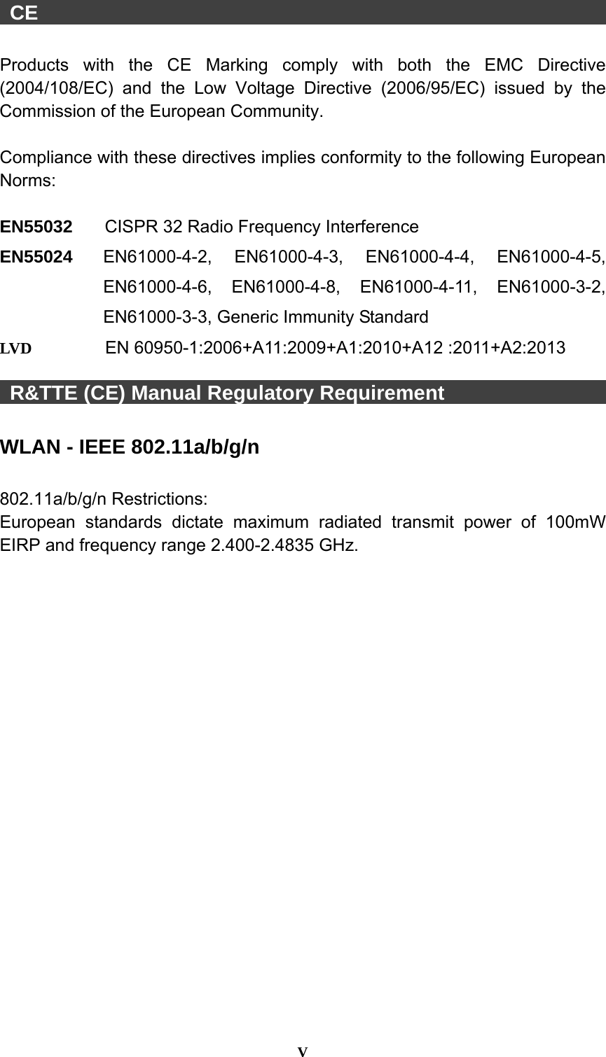
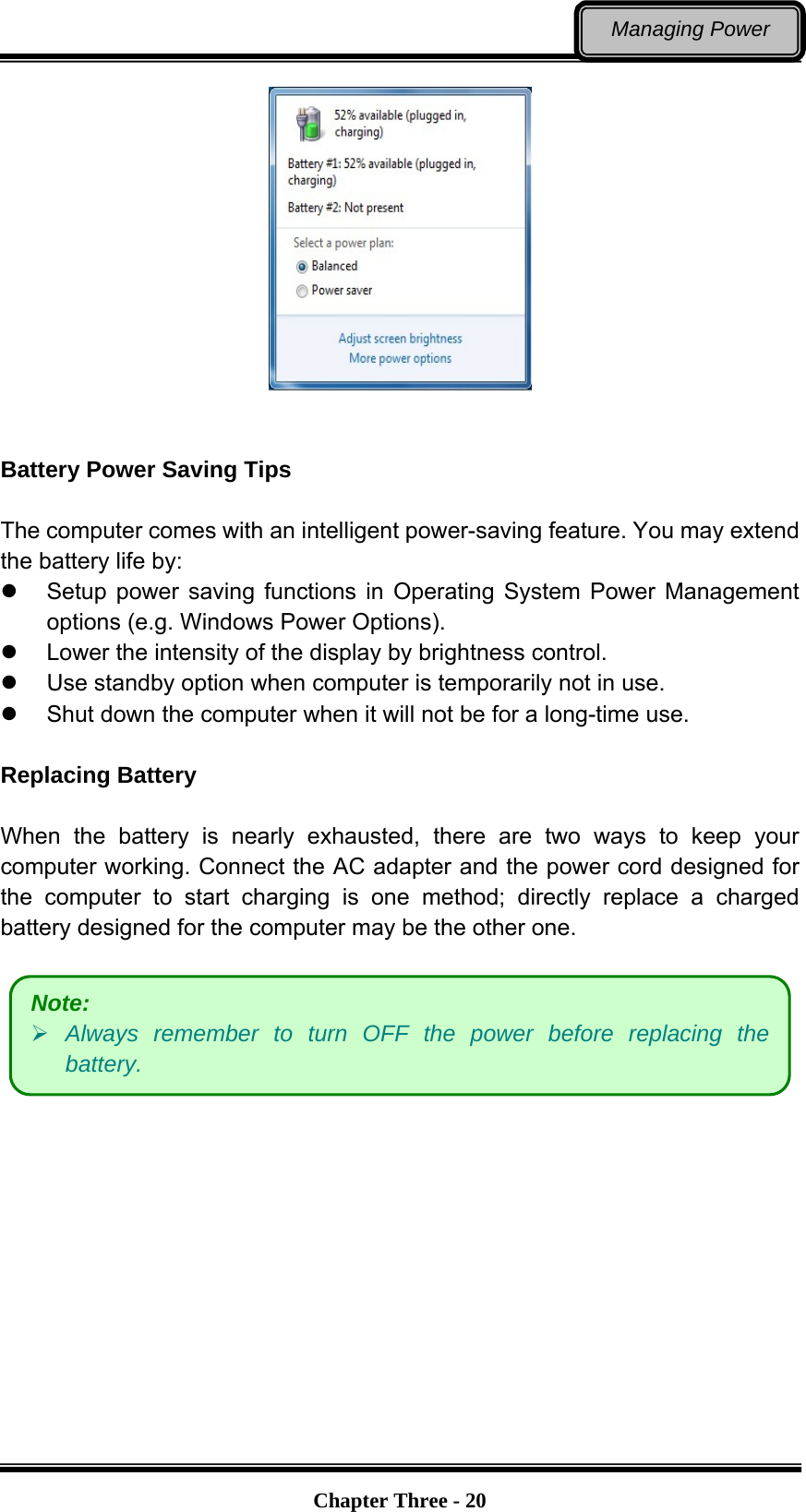
![Chapter Two - 13Operating Information Managing Solid Static Drive (SSD) The computer allows you to install at most four 2.5” type/ 7mm height standard SATAII/III interface SSDs. For standard, you can install 1st SATAIII SSD; for option, you can install 2nd SATAIII SSD, and 3rd~4th SATAII SSDs. For creating and setting up RAID, please use the Intel® RST (Rapid Storage Technology) to support RAID 0, 1, 5, 10 configurations. The following provides the steps to use RAID function: 1. Insert the required number of SSDs for RAID 0, 1, 5, 10, respectively. 2. Power on the computer, and press [F2] to enter BIOS. 3. Select Advanced menu => SATA Configuration => SATA Mode Selection => RAID 4. Restart your computer, and press [ctrl + I] when the option ROM screen appears during POST. 5. Now, you can setup RAID configuration following the on-screen instructions. Or, you can refer to the User Guide of Intel® Rapid Storage Technology on the Intel official website. RTC Battery backed up RTC (Real Time Clock/Calendar) is built in an on-board CMOS (Complementary Metal Oxide Semiconductor) chip. The RTC keeps track of the time and date while the computer is off. The CMOS chip also stores system setup information. RTC battery is also recharged when AC adapter is attached. Recharge the computer approximately once per month to ensure RTC operation. Note: It is recommended to use the same capacity size SSDs to configure RAID volume.](https://usermanual.wiki/MilDef-Crete/RW11/User-Guide-2941065-Page-26.png)


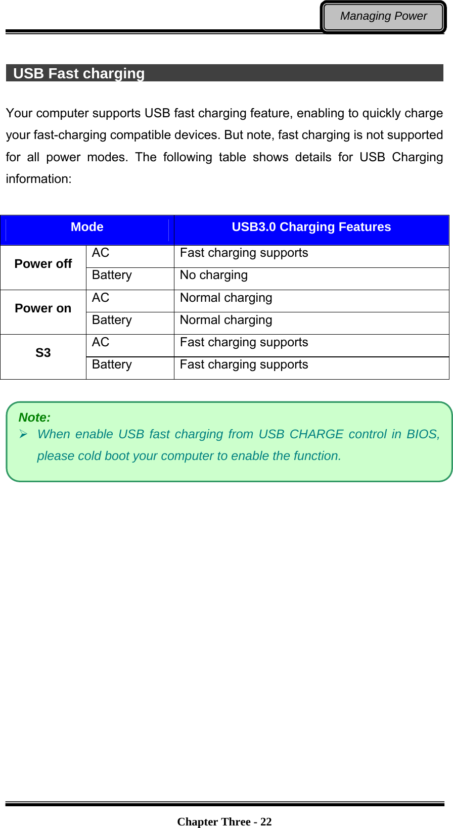
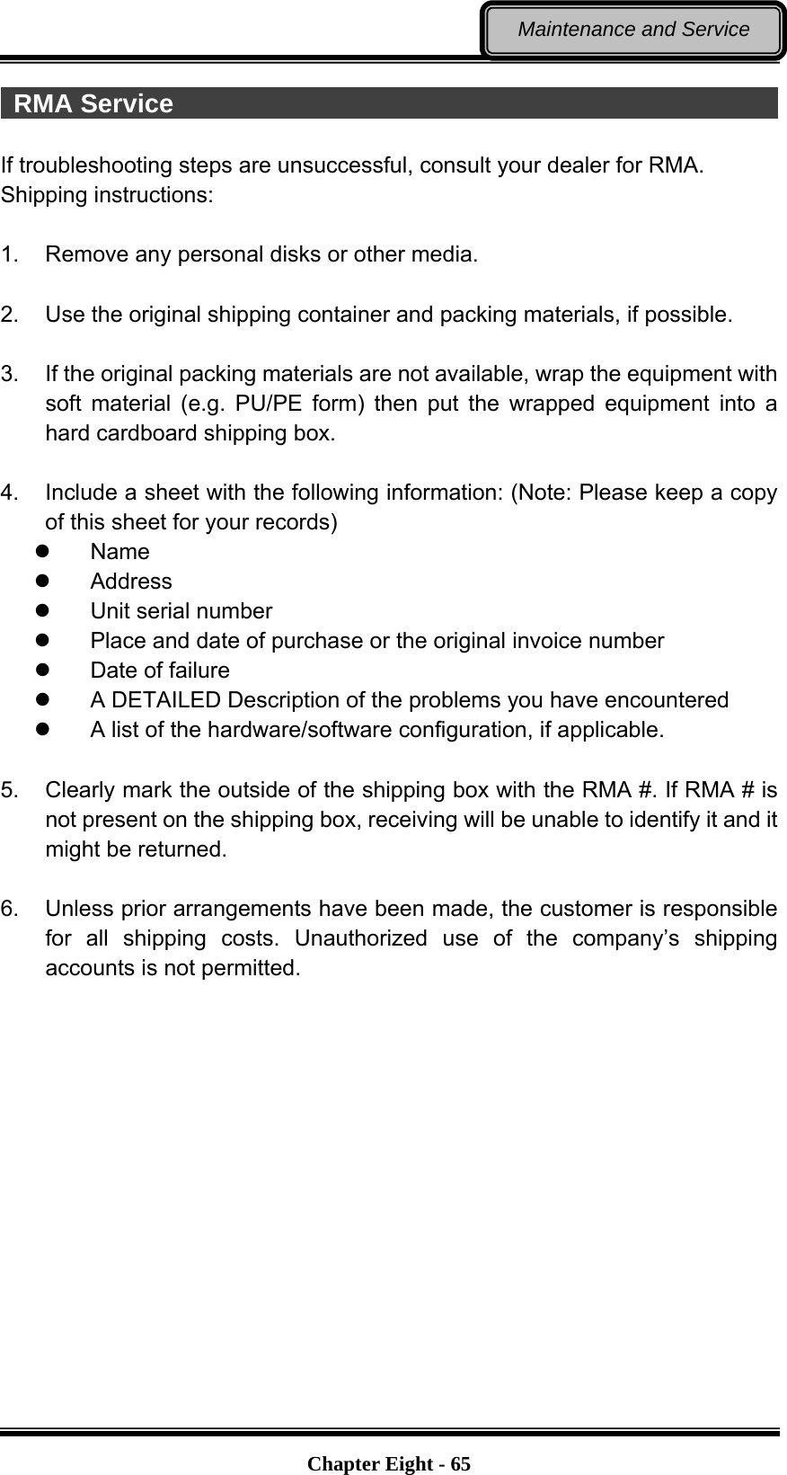
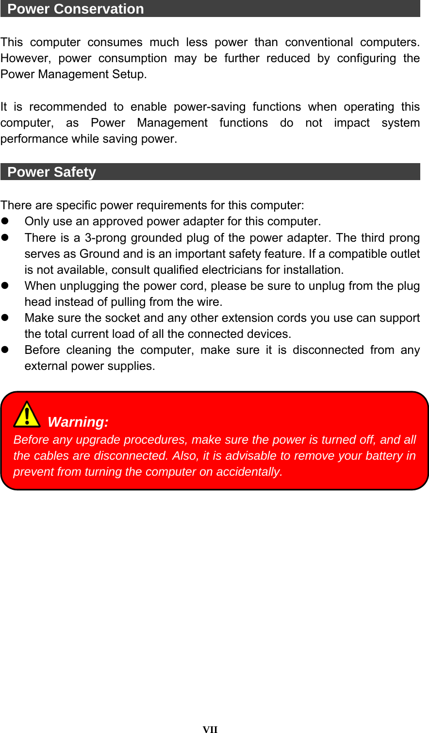
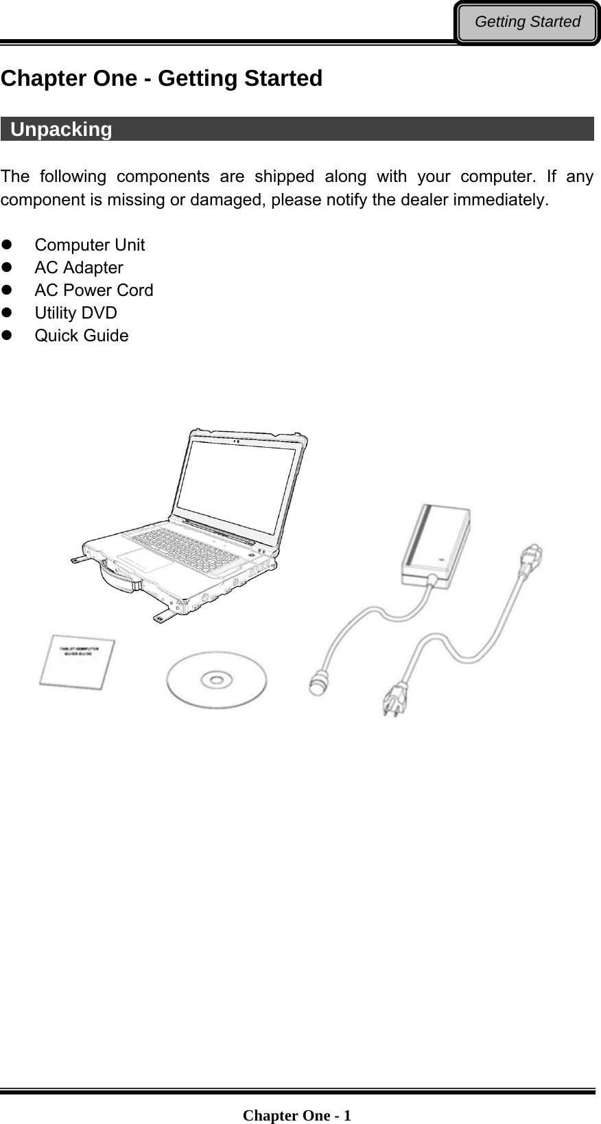
![Chapter Four - 23BIOS SetupChapter Four - BIOS Setup Press [F2] at boot up to enter BIOS setup. Use arrow keys to select options and [+/-] to modify them. When finished, move to “Exit” and press [Enter] then confirm save by pressing [Y]. Main Menu Aptio Setup Utility Main Advanced Chipset Boot Security Save & Exit Choose the system default language BIOS Information BIOS Vendor Core Version Compliancy Project Version Build Date and Time EC Version System Language [English] System Date [Mon 05/20/2013] System Time [16:19:20] Access Level Administrator →←: Select Screen ↑↓: Select Item Enter: Select –/+: Change Opt. F1: General Help F2: Previous Values F3: Optimized Defaults F4: Save & Exit ESC: Exit Main Menu Selections You can make the following selections on the Main Menu. Use the sub-menus for other selections. Feature Options Description System Date MM/DD/YYYY Set the Date. Use Tab to switch between Date elements System Time HH:MM:SS Set the Time. Use Tab to switch between Time elements. Note: The contents may vary depending on computer configurations. You can check your BIOS/EC Version on the main menu. Incorrect settings may cause system malfunction. To correct it, restore the Optimized Defaults with F3.](https://usermanual.wiki/MilDef-Crete/RW11/User-Guide-2941065-Page-36.png)
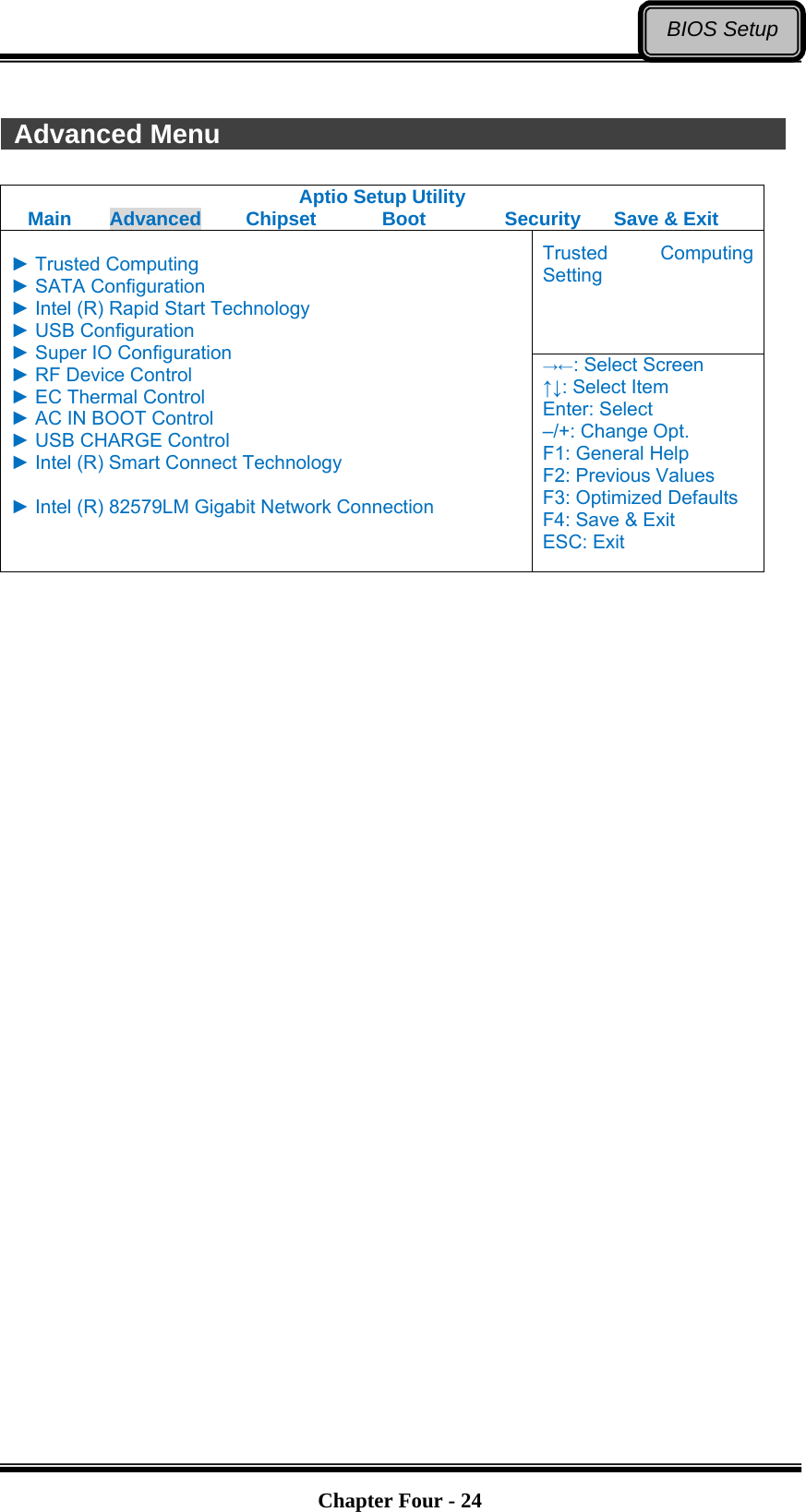
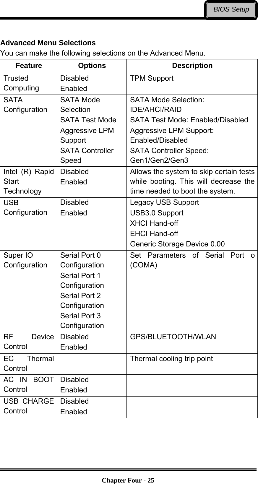
![Chapter Four - 26BIOS SetupFeature Options Description Intel Smart Connect Technology Disabled Enabled Intel Smart Connect Technology Settings Intel 82579LM Gigabit Network Connection NIC Configuration Blink LEDs (range 0/15 seconds) Link Status Configure Gigabit Ethernet device parameters Trusted Computing Sub-Menu Aptio Setup Utility Advanced Enables or Disables BIOS support for security device. O.S. will not show Security Device. TCG EFI protocol and INT1A interface will not be available. Configuration Security Device Support [Disabled] Current Status Information SUPPORT TURNED OFF →←: Select Screen ↑↓: Select Item Enter: Select –/+: Change Opt. F1: General Help F2: Previous Values F3: Optimized Defaults F4: Save & Exit ESC: Exit](https://usermanual.wiki/MilDef-Crete/RW11/User-Guide-2941065-Page-39.png)
![Chapter Four - 27BIOS SetupSATA Configuration Sub-Menu Aptio Setup Utility Advanced Determine how SATA controller(s) operate. SATA Mode Selection [AHCI] SATA Test Mode [Disabled] Aggressive LPM Support [Enabled] SATA Controller Speed [Gen3] Serial ATA Port 0 HGST HTS725050 (500.1GB) Software Preserve SUPPORTED Serial ATA Port 0 Empty Software Preserve Unknown Serial ATA Port 0 Empty Software Preserve Unknown →←: Select Screen ↑↓: Select Item Enter: Select –/+: Change Opt. F1: General Help F2: Previous Values F3: Optimized Defaults F4: Save & Exit ESC: Exit SATA Configuration Sub-Menu Selections You can make the following selections on the SATA configuration sub-menu. Feature Options Description SATA Mode Selection IDE AHCI RAID SATA Test Mode Disabled Enabled Enable or Disable Test Mode Aggressive LPM Support Disabled Enabled Enable PCH to aggressively enter link power state. SATA Controller Speed Gen1 Gen2 Gen3 Indicate the maximum speed the SATA controller can support.](https://usermanual.wiki/MilDef-Crete/RW11/User-Guide-2941065-Page-40.png)
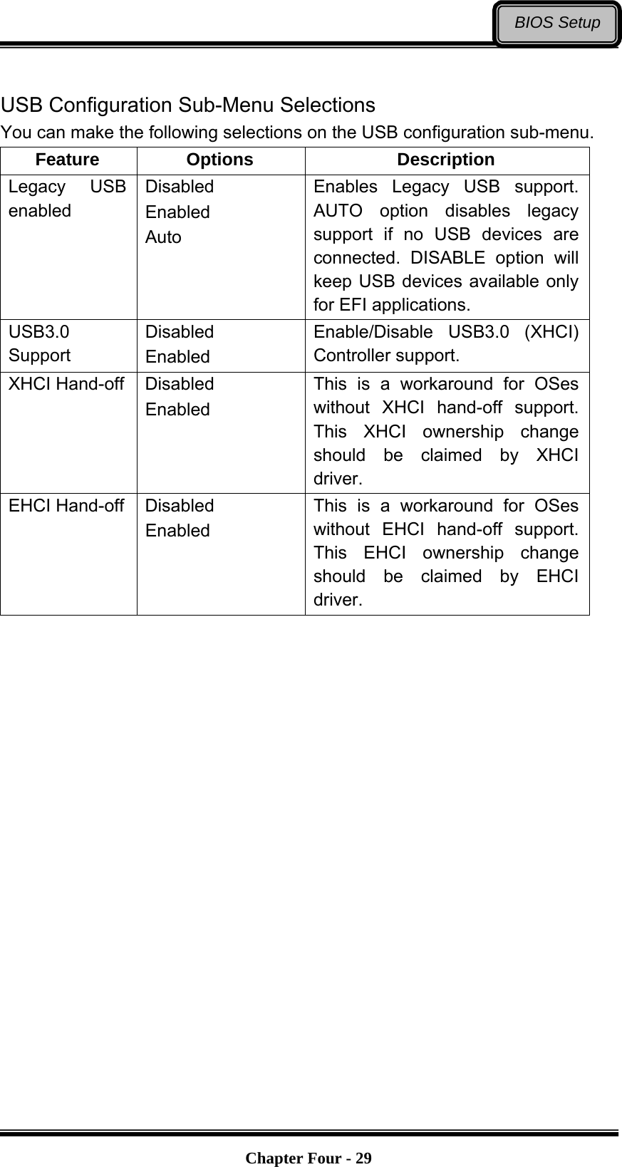
![Chapter Four - 28BIOS SetupIntel (R) Rapid Start Technology Sub-Menu Aptio Setup Utility Advanced Enable or disable Intel (R) Rapid Start Technology Intel (R) Rapis Start Technology [Disabled] →←: Select Screen ↑↓: Select Item Enter: Select –/+: Change Opt. F1: General Help F2: Previous Values F3: Optimized Defaults F4: Save & Exit ESC: Exit USB Configuration Sub-Menu Aptio Setup Utility Advanced Enables Legacy USB support. AUTO option disables legacy support if no USB devices are connected. Disable option will keep USB devices available only for EFI applications USB Configuration USB Devices: 2 Hubs Legacy USB Support [Enabled] USB3.0 Support [Enabled] XHCI Hand-off [Enabled] EHCI Hand-off [Enabled] →←: Select Screen ↑↓: Select Item Enter: Select –/+: Change Opt. F1: General Help F2: Previous Values F3: Optimized Defaults F4: Save & Exit ESC: Exit](https://usermanual.wiki/MilDef-Crete/RW11/User-Guide-2941065-Page-41.png)
![Chapter Four - 31BIOS SetupRF Device Control Configuration Sub-Menu Aptio Setup Utility Advanced RF Device Control Setting RF Device Control GPS STATUS Present GPS [Enabled] BT STATUS Present BLUETOOTH [Enabled] WLAN STATUS Present WLAN [Enabled] →←: Select Screen ↑↓: Select Item Enter: Select –/+: Change Opt. F1: General Help F2: Previous Values F3: Optimized Defaults F4: Save & Exit ESC: Exit RF Device Control Configuration Sub-Menu Selections You can make the following selections on the RF Security Control sub-menu. Feature Options Description GPS Disabled Enabled RF Device Control Setting BLUETOOTH Disabled Enabled RF Device Control Setting WLAN Disabled Enabled RF Device Control Setting](https://usermanual.wiki/MilDef-Crete/RW11/User-Guide-2941065-Page-44.png)
![Chapter Four - 32BIOS Setup EC Thermal Control Sub-Menu Aptio Setup Utility Advanced EC Thermal Control Setting EC Thermal Control Thermal cooling trip point [87 C] →←: Select Screen ↑↓: Select Item Enter: Select –/+: Change Opt. F1: General Help F2: Previous Values F3: Optimized Defaults F4: Save & Exit ESC: Exit AC IN BOOT Sub-Menu Aptio Setup Utility Advanced AC IN BOOT Setting AC IN BOOT Control AC IN BOOT Control [Disabled] →←: Select Screen ↑↓: Select Item Enter: Select –/+: Change Opt. F1: General Help F2: Previous Values F3: Optimized Defaults F4: Save & Exit ESC: Exit](https://usermanual.wiki/MilDef-Crete/RW11/User-Guide-2941065-Page-45.png)
![Chapter Four - 33BIOS SetupUSB CHARGE Control Sub-Menu Aptio Setup Utility Advanced USB CHARGE Setting USB CHARGE Control USB CHARGE Control [Disabled] →←: Select Screen ↑↓: Select Item Enter: Select –/+: Change Opt. F1: General Help F2: Previous Values F3: Optimized Defaults F4: Save & Exit ESC: Exit Intel Smart Connect Technology Sub-Menu Aptio Setup Utility Advanced Enable/Disable ISCT Configuration ISCT Configuration [Disabled] →←: Select Screen ↑↓: Select Item Enter: Select –/+: Change Opt. F1: General Help F2: Previous Values F3: Optimized Defaults F4: Save & Exit ESC: Exit Note: After enabling USB fast charge function, please cold boot your computer.](https://usermanual.wiki/MilDef-Crete/RW11/User-Guide-2941065-Page-46.png)
![Chapter Four - 34BIOS SetupIntel 82579LM Gigabit Network Connection Sub-Menu Aptio Setup Utility Advanced Click to configure the network device port PORT CONFIGURATION MENU NIC Configuration Blink LEDs (range 0-15 seconds) 0 PORT CONFIGURATION INFORMATION UEFI Driver: Intel PRO/1000 5.0.12 Adapter PBA: FFFFFF-OFF Chip Type: Intel PCH2 PCI Device ID 1502 PCI Bus:Device:Function: 0:25:0 Link Status [Disconnected] Factory MAC Address: 88:88:88:88:87:88 →←: Select Screen ↑↓: Select Item Enter: Select –/+: Change Opt. F1: General Help F2: Previous Values F3: Optimized Defaults F4: Save & Exit ESC: Exit INTEL 82579LM Gigabit Network Connection Sub-Menu Selections You can make the following selections on the RF Security Control sub-menu. Feature Options Description NIC Configuration LINK Speed Change link speed and duplex for current port. Blink LEDs (range 0-15 seconds) Blink LEDs for the specified duration (up to 15 seconds).](https://usermanual.wiki/MilDef-Crete/RW11/User-Guide-2941065-Page-47.png)
![Chapter Four - 35BIOS SetupNetwork Stack Configuration Sub-Menu Aptio Setup Utility Advanced Wait time to press ESC key to abort the PXE boot Network Stack [Enabled] Ipv4 PXE Support [Enabled] Ipv6 PXE Support [Enabled] PXE boot wait time 0 →←: Select Screen ↑↓: Select Item Enter: Select –/+: Change Opt. F1: General Help F2: Previous Values F3: Optimized Defaults F4: Save & Exit ESC: Exit Network Stack Configuration Sub-Menu Selections You can make the following selections on the Network stack configuration sub-menu. Feature Options Description PXE boot wait time 0~5 Wait time to press ESC key to abort the PXE boot Note: The value of PXE boot wait time can be set from 0~5.](https://usermanual.wiki/MilDef-Crete/RW11/User-Guide-2941065-Page-48.png)
![Chapter Four - 36BIOS Setup Chipset Menu Aptio Setup Utility Main Advanced Chipset Boot Security Save & Exit PCH Parameter ► PCH-IO Configuration ► System Agent (SA) Configuration →←: Select Screen ↑↓: Select Item Enter: Select –/+: Change Opt. F1: General Help F2: Previous Values F3: Optimized Defaults F4: Save & Exit ESC: Exit PCH-IO Configuration Sub-Menu Aptio Setup Utility Chipset PCI Express Configuration settings Intel PCH RC Version 1.6.0.0 Intel PCH SKU Name QM77 Intel PCH Rev ID 04/C1 ► PCI Express Configuration ► USB Configuration ► PCH Azalia Configuration PCH LAN Controller [Enabled] Wake on LAN [Enabled] →←: Select Screen ↑↓: Select Item Enter: Select –/+: Change Opt. F1: General Help F2: Previous Values F3: Optimized Defaults F4: Save & Exit ESC: Exit](https://usermanual.wiki/MilDef-Crete/RW11/User-Guide-2941065-Page-49.png)
![Chapter Four - 37BIOS Setup PCI Express Configuration Sub-Menu Aptio Setup Utility Advanced Enable or disable PCI Express Clock Gating for each root port PCI Express Configuration PCI Express Clock Gating [Enabled] DMI Link ASPM Control [Enabled] DMIO Link Extended Synch Control [Disabled] PCIe-USB Glitch W/A [Disabled] Subtractive Decode [Disabled] ► PCI Express Root Port 1 ► PCI Express Root Port 2 ► PCI Express Root Port 3 ► PCI Express Root Port 4 ► PCI Express Root Port 5 PCIE Port 6 is assigned to LAN ► PCI Express Root Port 7 ► PCI Express Root Port 8 →←: Select Screen ↑↓: Select Item Enter: Select –/+: Change Opt. F1: General Help F2: Previous Values F3: Optimized Defaults F4: Save & Exit ESC: Exit USB Configuration Sub-Menu Aptio Setup Utility Advanced Enable or disable XHCI Pre-Boot Driver support USB Configuration XHCI Pre-Boot Driver [Enabled] xHCI Mode [Smart Auto] HS Port #1 Switchable [Enabled] HS Port #2 Switchable [Enabled] HS Port #3 Switchable [Enabled] HS Port #4 Switchable [Enabled] xHCI Streams [Enabled] EHCI1 [Enabled] EHCI2 [Enabled] USB Ports Per-Port Disable Control [Disabled] →←: Select Screen ↑↓: Select Item Enter: Select –/+: Change Opt. F1: General Help F2: Previous Values F3: Optimized Defaults F4: Save & Exit ESC: Exit](https://usermanual.wiki/MilDef-Crete/RW11/User-Guide-2941065-Page-50.png)
![Chapter Four - 38BIOS Setup PCH Azaliz Configuration Sub-Menu Aptio Setup Utility Advanced Control Detection of the Azalia device. PCH Azalia Configuration Azalia [Auto] Azalia Docking Support [Disabled] Azalia PME [Disabled] Azalia Interbal HDMI Codec [Enabled] Azalia HDMI codec Port B [Enabled] Azalia HDMI codec Port C [Enabled] Azalia HDMI codec Port D [Enabled] →←: Select Screen ↑↓: Select Item Enter: Select –/+: Change Opt. F1: General Help F2: Previous Values F3: Optimized Defaults F4: Save & Exit ESC: Exit](https://usermanual.wiki/MilDef-Crete/RW11/User-Guide-2941065-Page-51.png)
![Chapter Four - 39BIOS Setup Boot Menu Aptio Setup Utility Main Advanced Chipset Boot Security Save & Exit Select boot mode LEGACY/UEFI Boot mode select [UEFI] FIXED Boot ORDER Priorities Boot Option #1 [Hard Disk: Windows B…] Boot Option #2 [CD/DVD] Boot Option #3 [USB Hard Disk] Boot Option #4 USB CD/DVD] Boot Option #5 [USB Key] Boot Option #6 [USB Floppy] Boot Option #7 [Network] ►CSM parameters ►UEFI Hard Disk Drive BBS Priorities ►UEFI NETWORK Drive BBS Priorities →←: Select Screen ↑↓: Select Item Enter: Select –/+: Change Opt. F1: General Help F2: Previous Values F3: Optimized Defaults F4: Save & Exit ESC: Exit The system will try to boot from device on top then the 2nd and so on. If there is more than one device in each category, only the device on top of sub-menu can boot up. Boot Menu Selections You can make the following selections on the Boot menu. Feature Options Description Boot mode select LEGACY UEFI Select boot mode LEGACY/UEFI Boot Option #1 Hard Disk: Windows Boot Manager CD/DVD USB Hard Disk USB CD/DVD USB Key USB Floppy Network Disabled Sets the system boot order](https://usermanual.wiki/MilDef-Crete/RW11/User-Guide-2941065-Page-52.png)
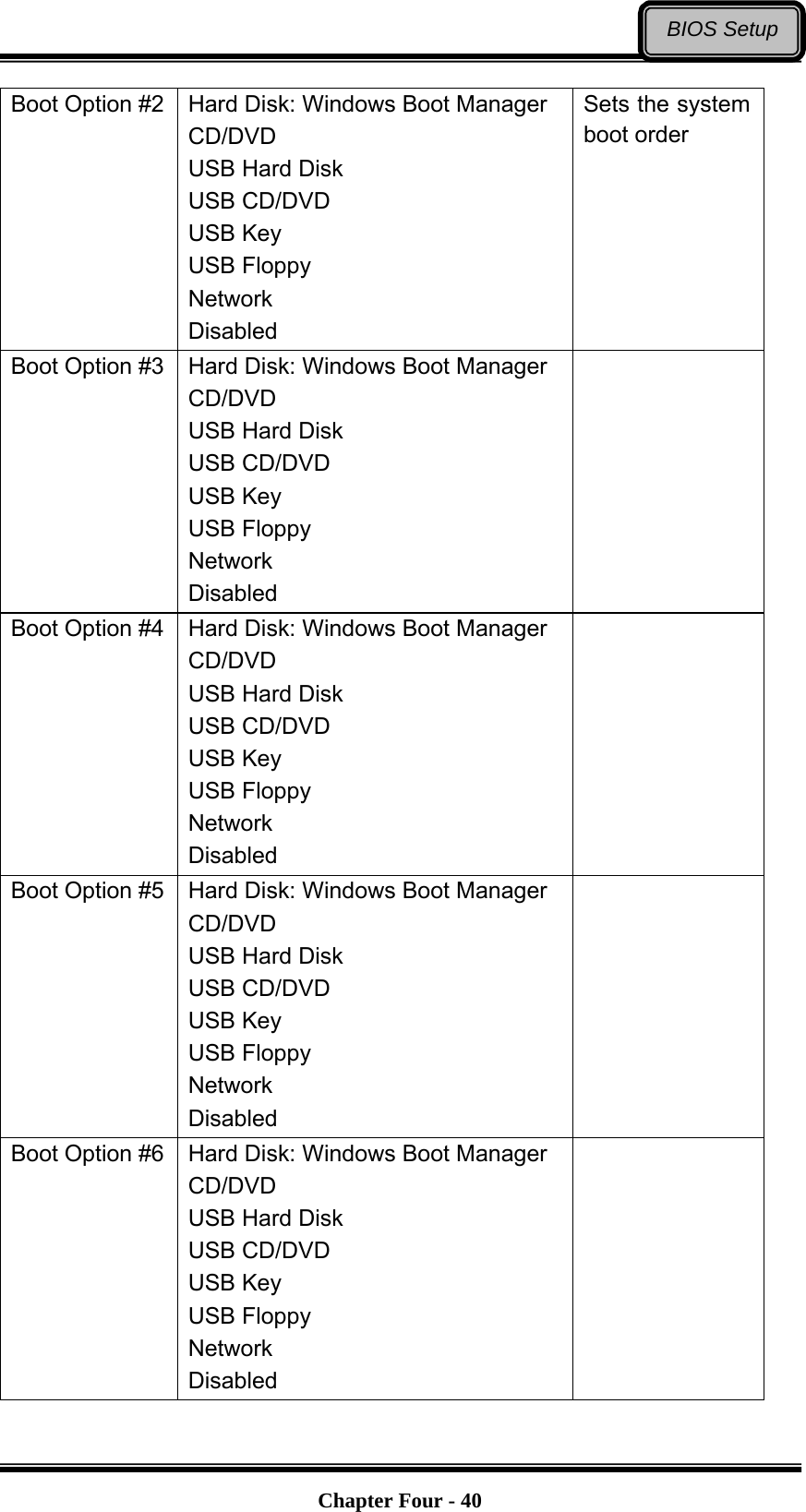
![Chapter Four - 41BIOS SetupBoot Option #7 Hard Disk: Windows Boot Manager CD/DVD USB Hard Disk USB CD/DVD USB Key USB Floppy Network Disabled CSM parameters Launch CSM Boot option filter Launch PXE OpROM policy Launch Storage OpROM policy Launch Video OpROM policy Other PCI device ROM priority OpROM execution, boot options filter, etc UEFI Hard Disk Drive BBS Priorities Boot Option #1 [Windows Boot Manager] Boot Option #2 [Windows Boot Manager] Sets the system boot order UEFI NETWORK Drive BBS Priorities Boot Option #1 [UEFI: IP6 Intel] Boot Option #2 [UEFI: IP4 Intel] Sets the system boot order Note: IPv6 is supported only under UEFI mode, while IPv4 can be supported under both UEFI and Legacy mode.](https://usermanual.wiki/MilDef-Crete/RW11/User-Guide-2941065-Page-54.png)