MilDef Crete RK886EX Notebook Computer with 802.11 a/b/g radio User Manual RK886EX UserMan 0703
MilDef Crete Inc. Notebook Computer with 802.11 a/b/g radio RK886EX UserMan 0703
UserManual.wiki
>
MilDef Crete
>
RK886EX User Manual
Manual
Navigation menu
Upload a User Manual
Namespaces
Wiki Guide
HTML
PDF
Info
Views
User Manual
Discussion / Help
Navigation
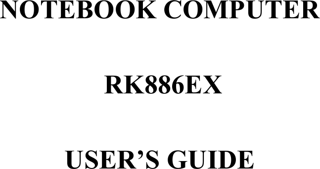
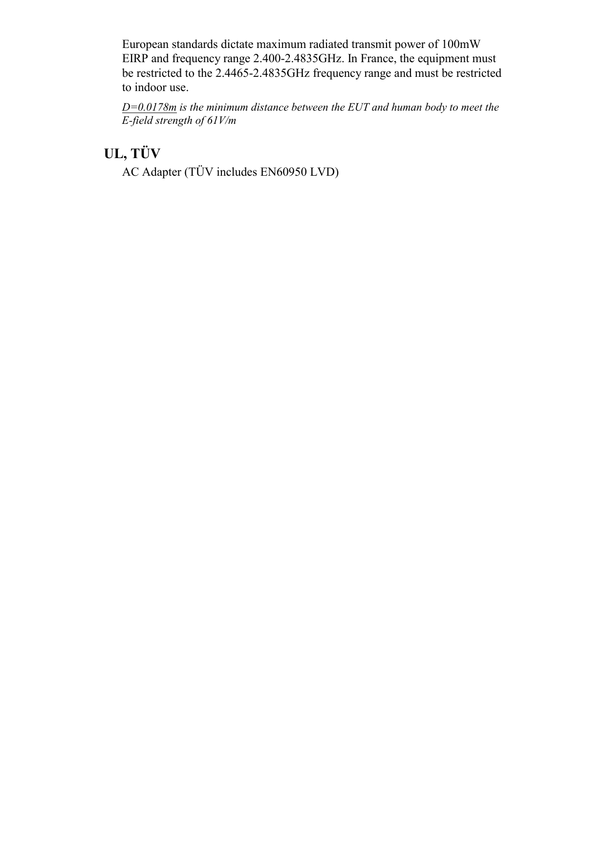

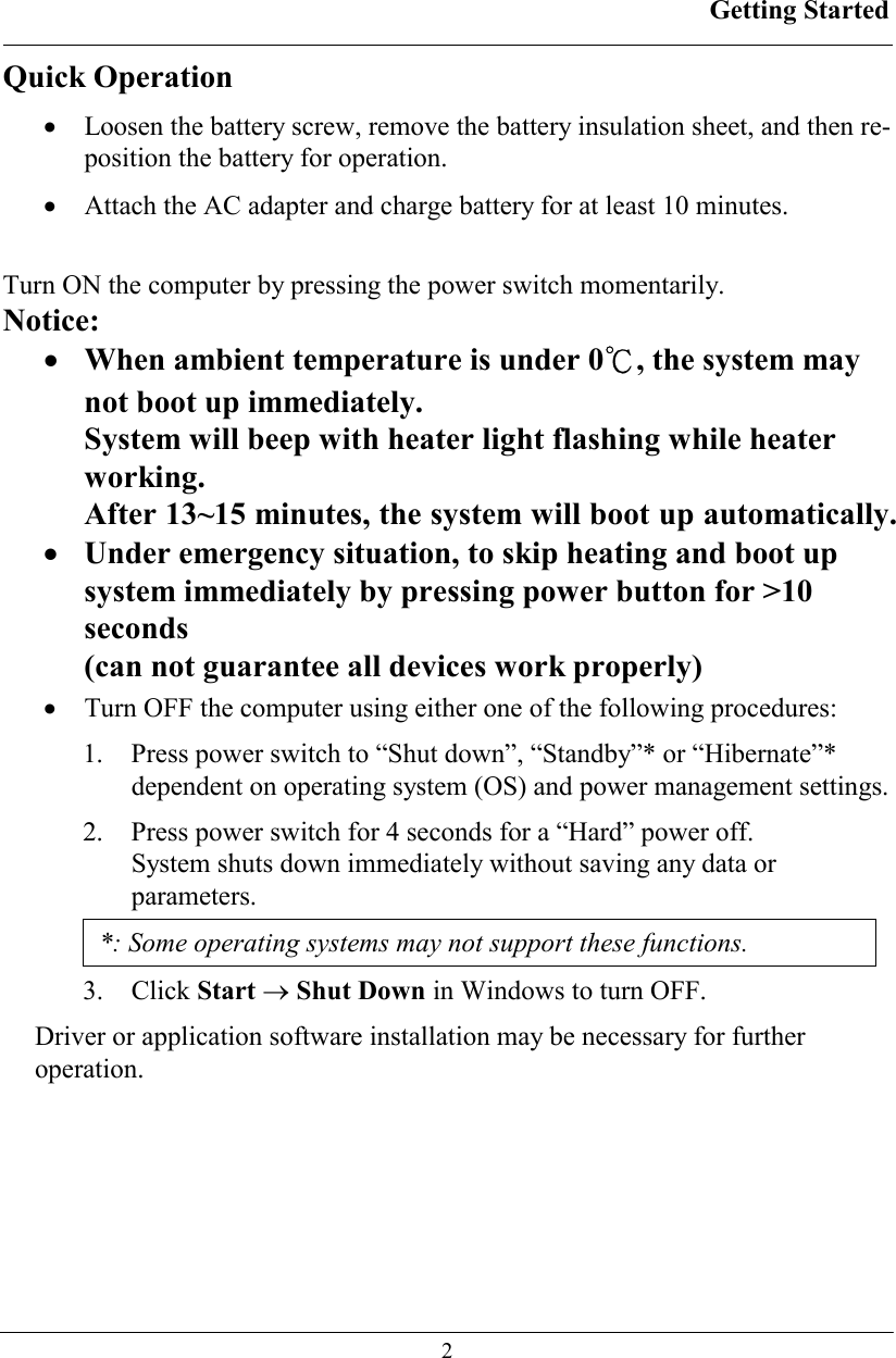
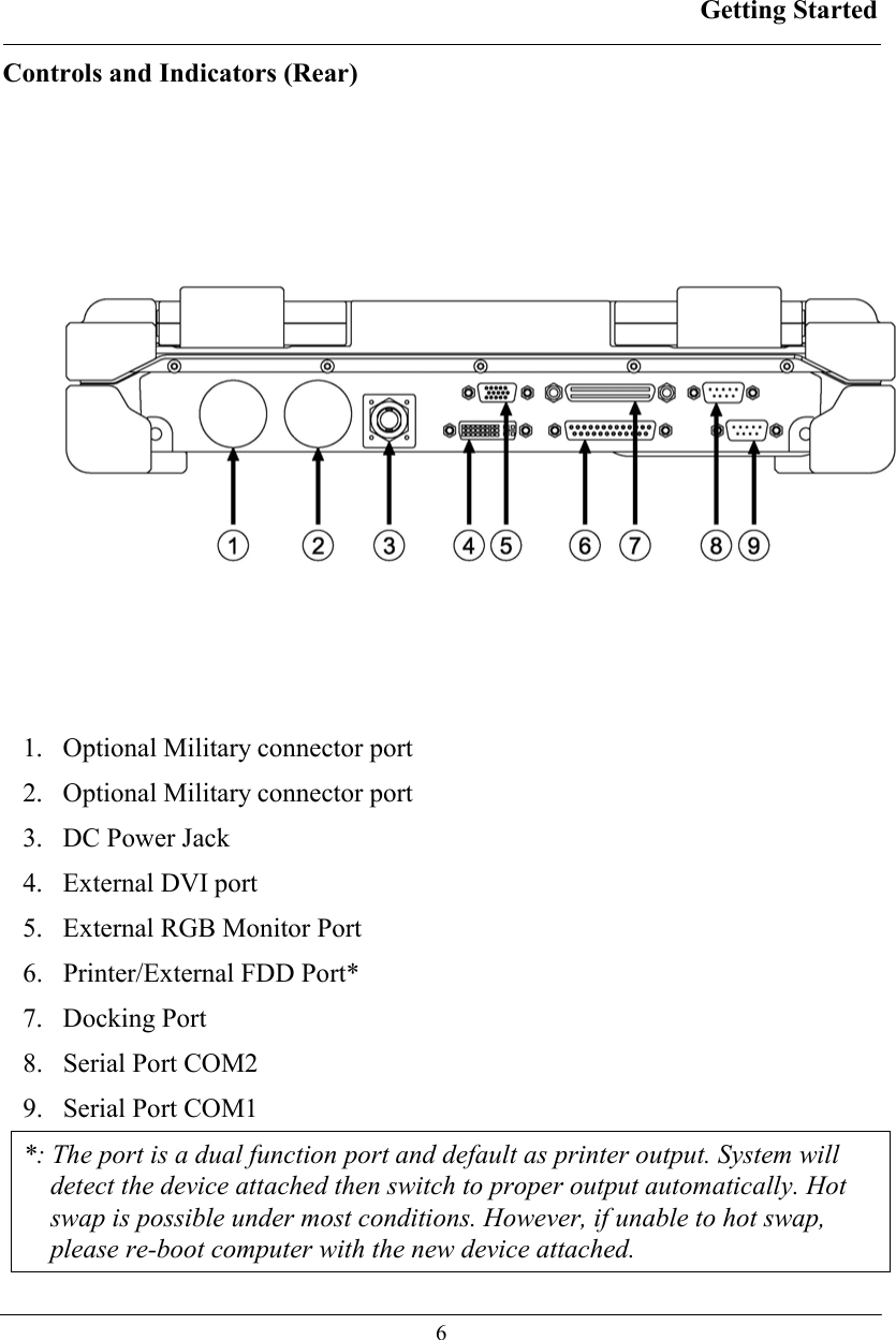
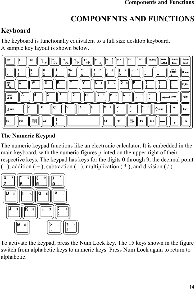
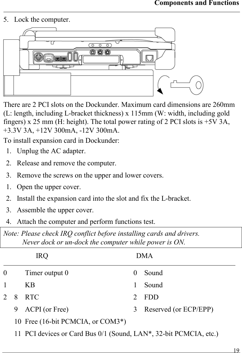
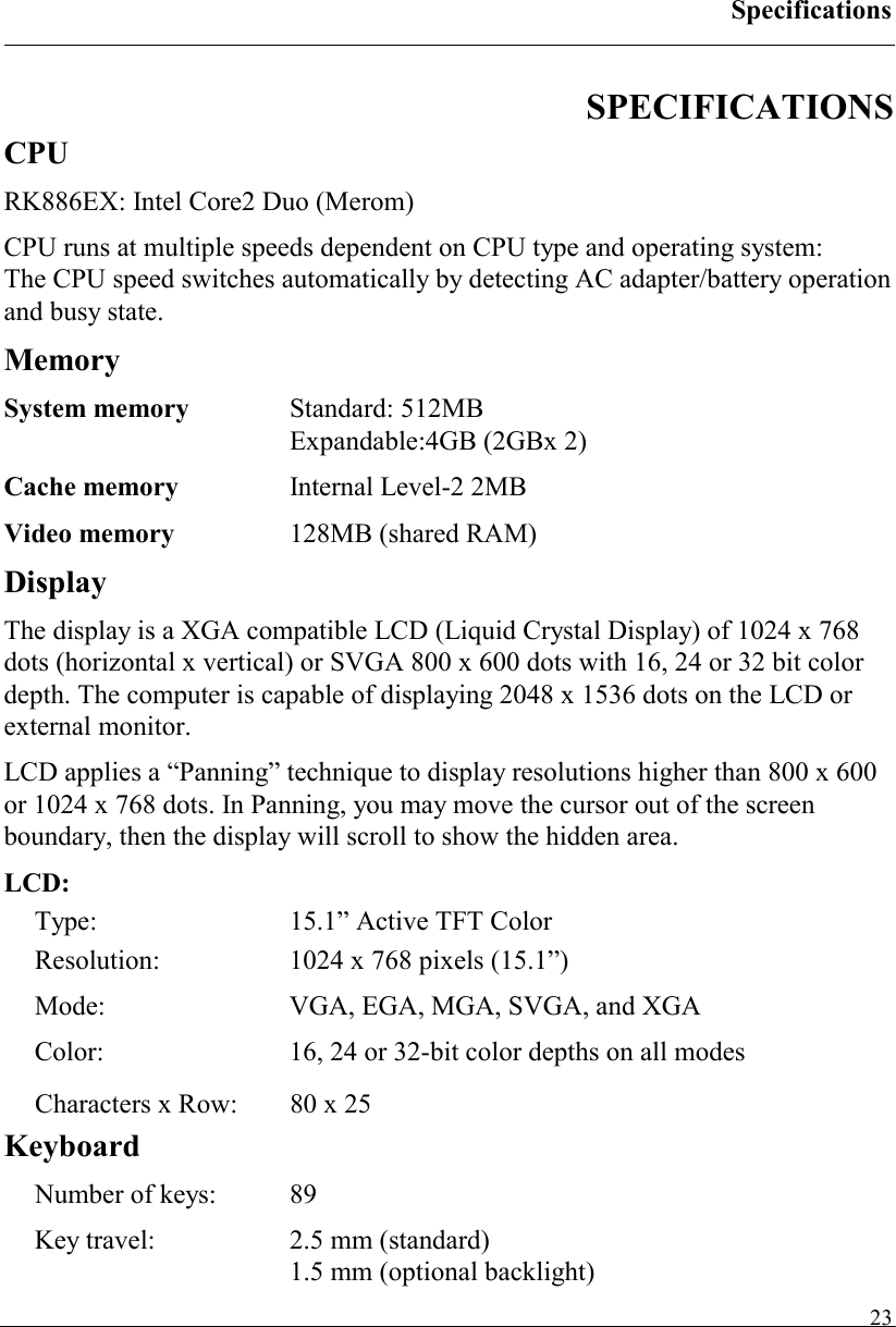
![Components and Functions 15Keyboard Backlight (optional) Press [Fn] [F5] key for approximately 1 second turns keyboard backlight ON or OFF. Floppy Disk Drive The computer comes with a 3.5" 1.44MB floppy disk drive (FDD). The 1.44MB FDD can also read and write 720KB double side double density diskette. It is recommended that high density (2HD marking) diskette been used only. FDD can be removed and swapped with CD-ROM drive or 2nd battery. When CD-ROM drive or 2nd battery is installed, you may still use FDD by connecting it via the rear DB-25 port. Printer Cable For most printers there is no special requirement in connection. However, some printer cables do not contain all 25 wires. To avoid malfunction, the printer adapter cable comes with your computer should be attached to the printer cable. The purpose is to re-connect all the ground pins. Devices equivalent to printer such as scanner, Laplink cable, etc. also need this cable. Please note do not use the FDD cable as printer adapter cable. Hard Disk Drive The Hard Disk Drive (HDD) is a 2.5” type standard SATA interface data storage device. HDD and FDD, CD-ROM drives are removable. This provides convenience and security. They can ONLY be removed while the power is OFF.](https://usermanual.wiki/MilDef-Crete/RK886EX/User-Guide-818154-Page-23.png)
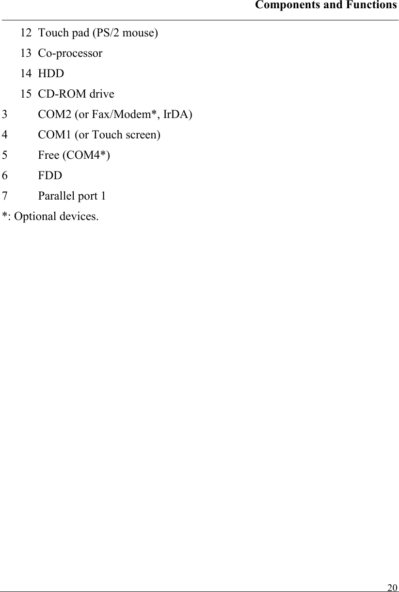
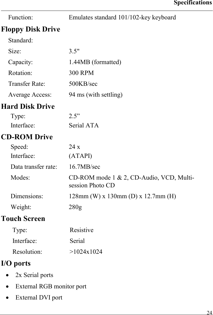
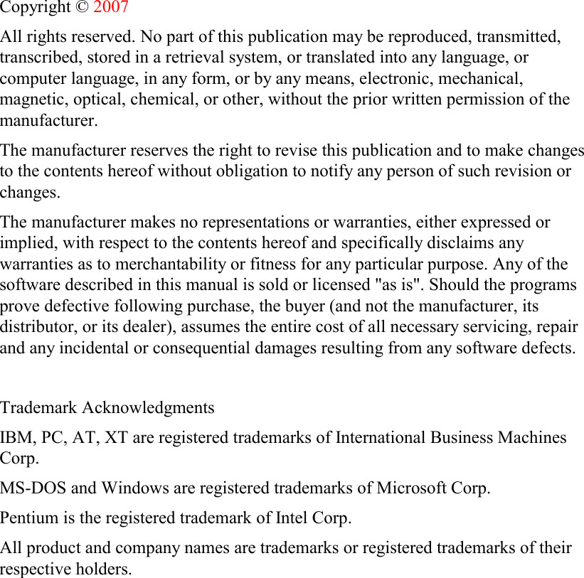
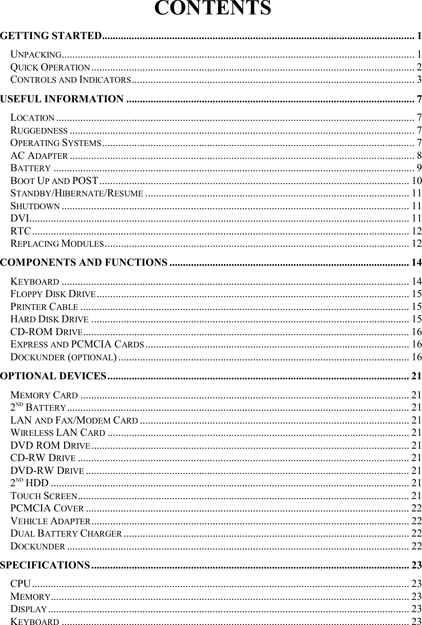
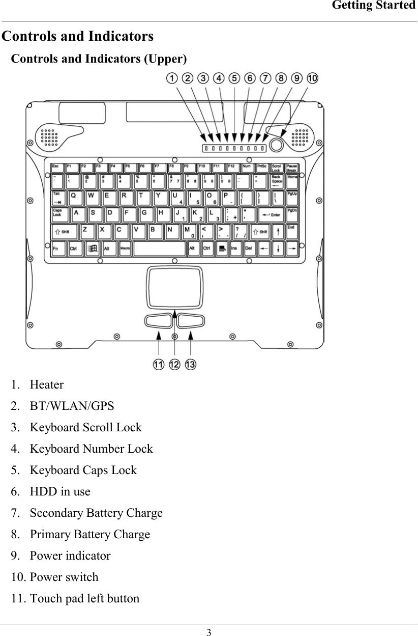
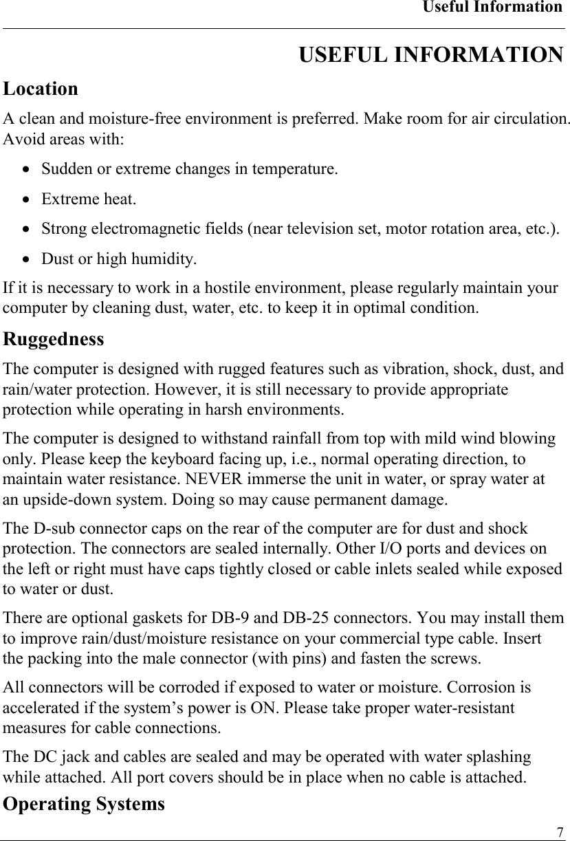
![BIOS Setup 28BIOS SETUP Press [F2] at boot up to enter BIOS setup. Use arrow keys to select options and [+/-] to modify them. When finished, move to ”Exit” and press [Enter] then confirm save by pressing [Y]. Main Menu Phoenix TrustedCore(tm) Setup Utility Main Advanced Security TPM State Boot Exit Item Specific Help System Time: [16:19:20] System Date: [03/02/2007] Legacy Diskette A: [1.44/1.25MB 3½"] • IDE Channel 0 Master [None] • IDE Channel 0 Slave [None] • SATA Port 0 [None] • SATA Port 1 [None] System Memory: 640 KB Extended Memory: 522752 KB <Tab>, <Shift-Tab>, or <Enter> selects field F1 Help ↑↓ Select Item –/+ Change Values F9 Setup Defaults Esc Exit ↔ Menu Enter Select ► Sub-Menu F10 Save and Exit Note: The contents may vary depending on computer configurations. Main Menu Selections You can make the following selections on the Main Menu. Use the sub menus for other selections. Feature Options Description System Time HH:MM:SS Set the system time Hour, Minute, Second. System Date MM/DD/YYYY Set the system date Month, Day, Year.](https://usermanual.wiki/MilDef-Crete/RK886EX/User-Guide-818154-Page-36.png)
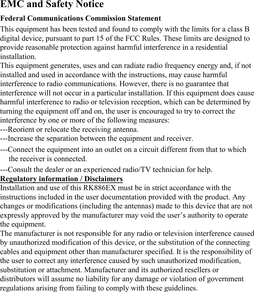
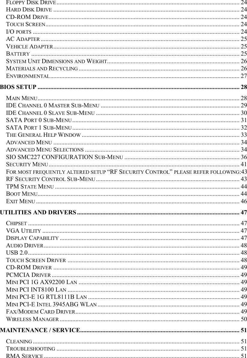
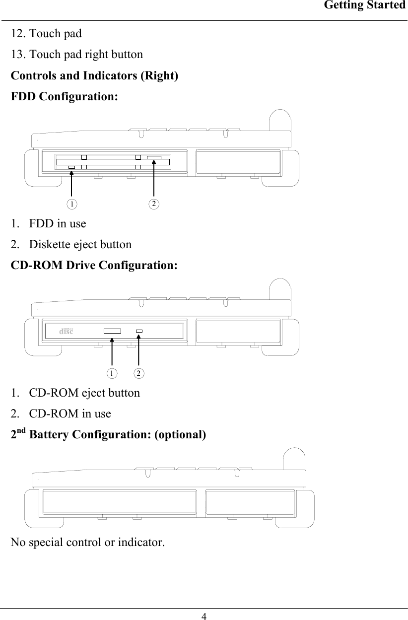
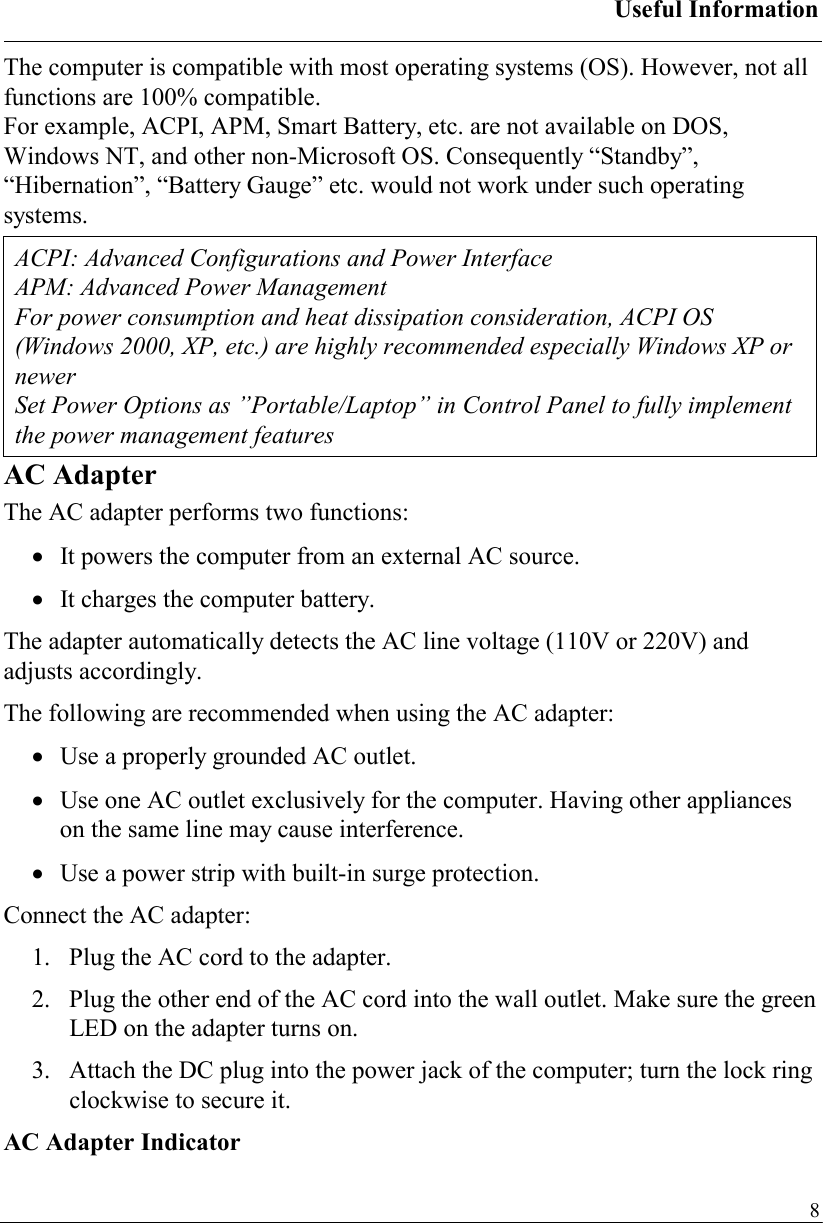
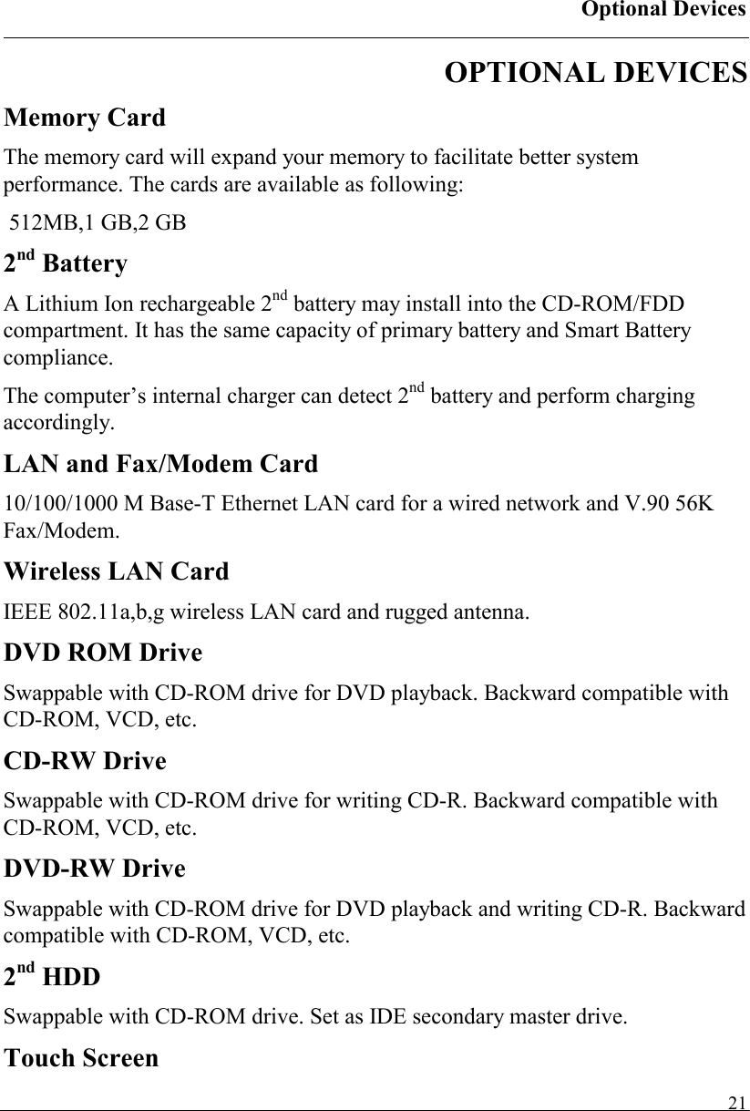
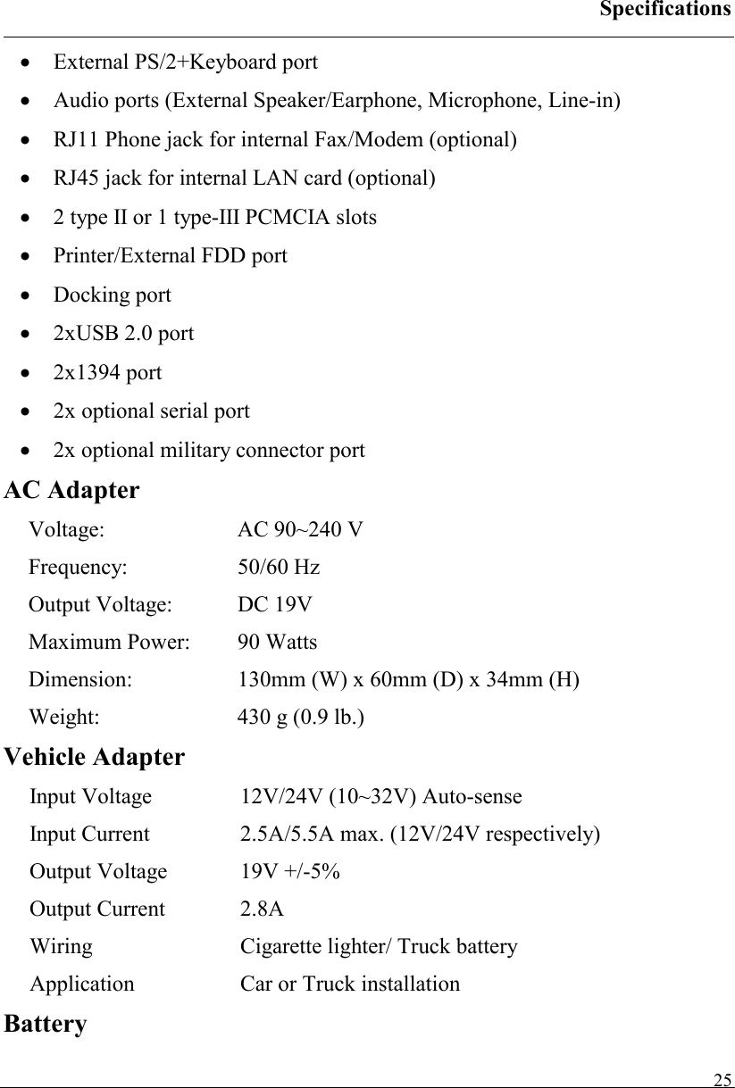
![BIOS Setup 29Legacy Diskette A Disabled 360 Kb 5¼" 1.2 MB 5¼"720 Kb 3½"1.44/1.25 MB3½"2.88 MB 3½"Select floppy type. Note that 1.25 MB 3½” references a 1024 byte/sector Japanese media format. The 1.25MB, 3½" diskette requires a 3-Mode floppy-disk drive. IDE Channel 0 Master Sub-Menu Phoenix TrustedCore(tm) Setup Utility Main IDE Channel 0 Master [None] Item Specific Help Type: [Auto] Multi-Sector Transfers: [Disabled] LBA Mode Control: [Disabled] 32 Bit I/O: [Disabled] Transfer Mode: [Standard] Ultra DMA Mode: [Disabled] User = you enter parameters of hard-disk drive installed at this connection. Auto = autotypes hard-disk drive installed here. CD-ROM = a CD-ROM drive is installed here. ATAPI Removable = removable disk drive is installed here. F1 Help ↑↓ Select Item –/+ Change Values F9 Setup Defaults Esc Exit ↔ Menu Enter Select ► Sub-Menu F10 Save and Exit IDE Channel 0 Master Sub-Menu Selections You can make the following selections on the IDE Channel 0 Master sub menu. Feature Options Description](https://usermanual.wiki/MilDef-Crete/RK886EX/User-Guide-818154-Page-37.png)
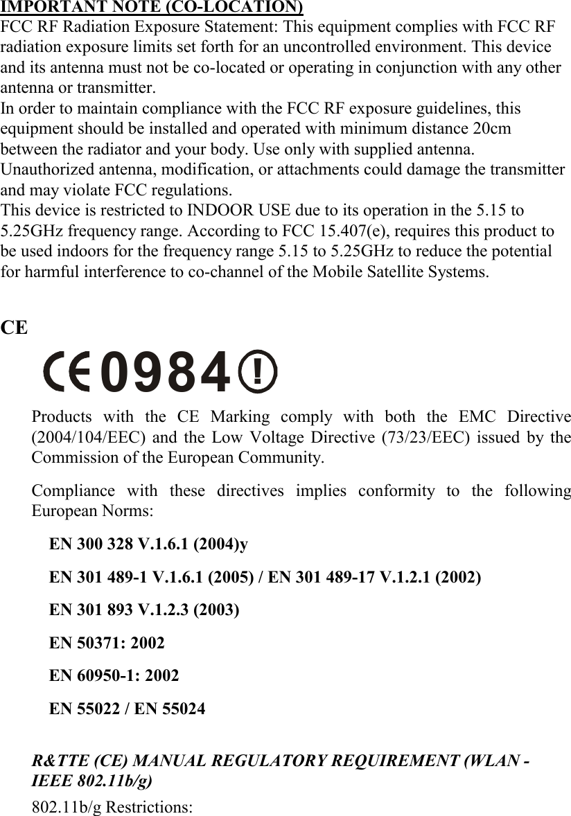
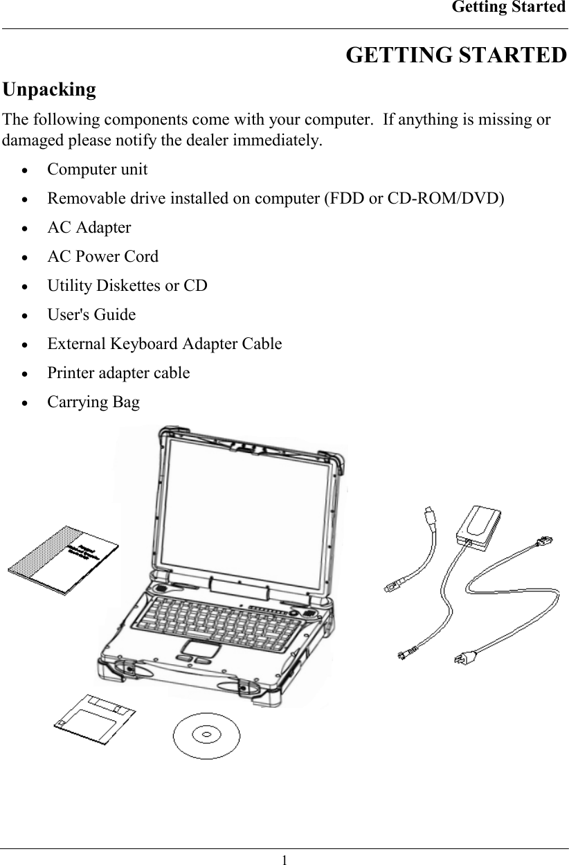
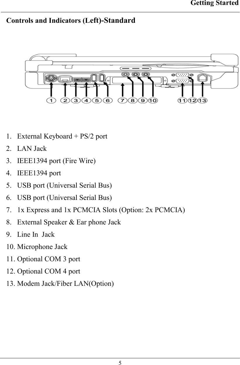
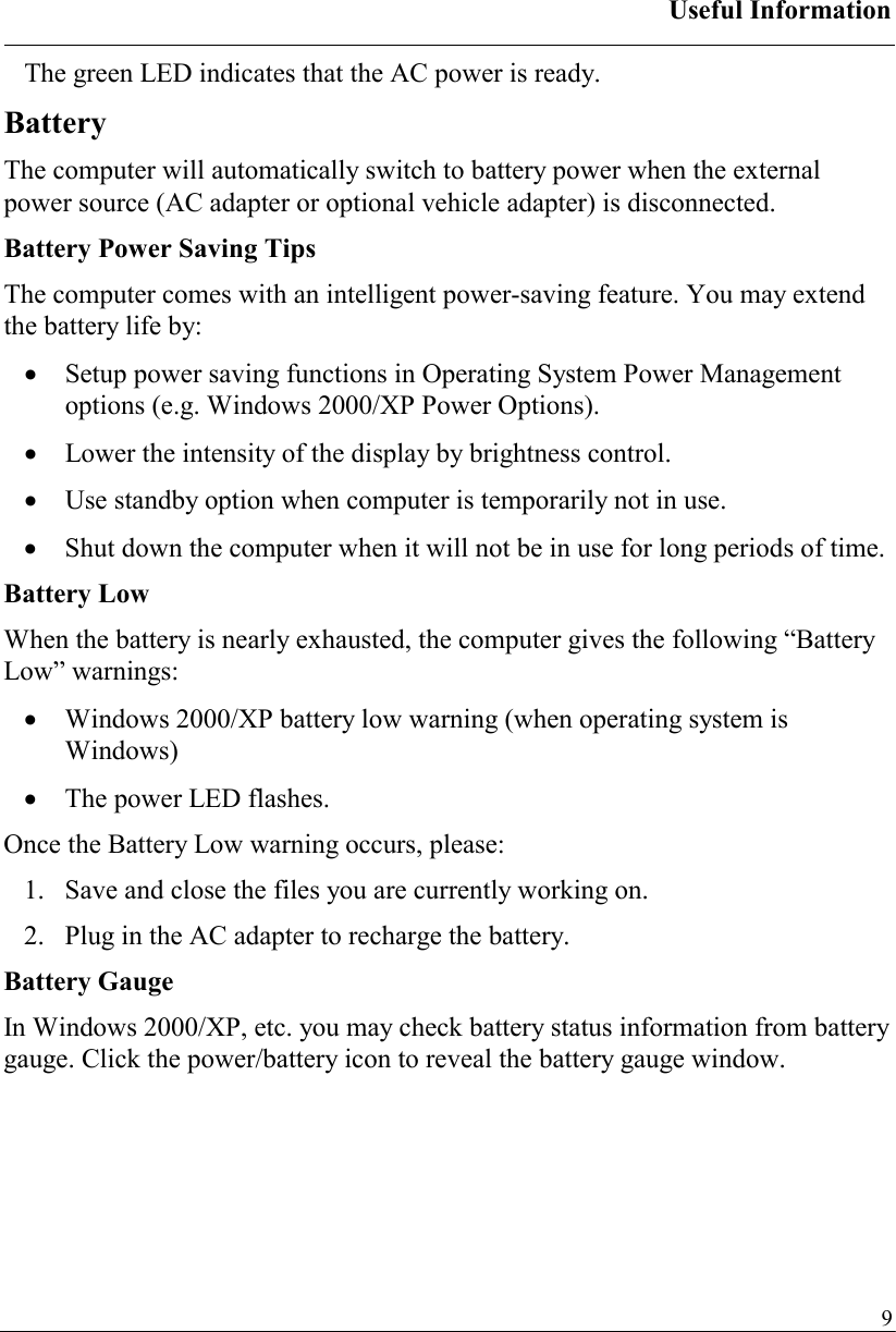
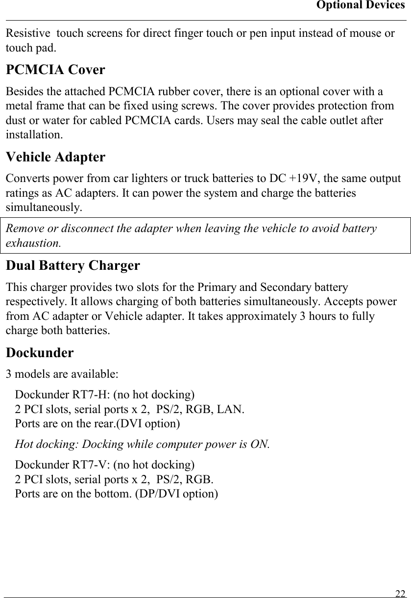
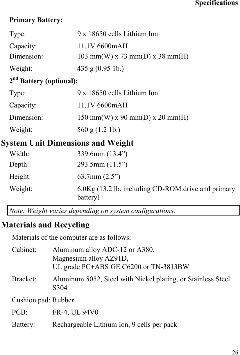
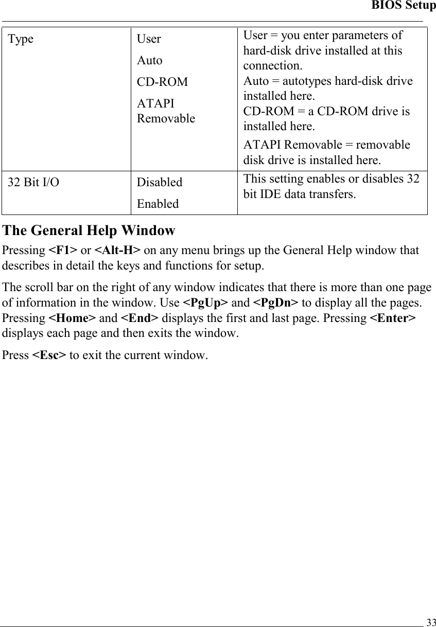
![BIOS Setup 30Type User Auto CD-ROM ATAPI Removable User = you enter parameters of hard-disk drive installed at this connection. Auto = autotypes hard-disk drive installed here. CD-ROM = a CD-ROM drive is installed here. ATAPI Removable = removable disk drive is installed here. 32 Bit I/O Disabled Enabled This setting enables or disables 32 bit IDE data transfers. IDE Channel 0 Slave Sub-Menu Phoenix TrustedCore(tm) Setup Utility Main IDE Channel 0 Slave [None] Item Specific Help Type: [Auto] Multi-Sector Transfers: [Disabled] LBA Mode Control: [Disabled] 32 Bit I/O: [Disabled] Transfer Mode: [Standard] Ultra DMA Mode: [Disabled] SMART Monitoring: Disabled User = you enter parameters of hard-disk drive installed at this connection. Auto = autotypes hard-disk drive installed here. CD-ROM = a CD-ROM drive is installed here. ATAPI Removable = removable disk drive is installed here. F1 Help ↑↓ Select Item –/+ Change Values F9 Setup Defaults Esc Exit ↔ Menu Enter Select ► Sub-Menu F10 Save and Exit IDE Channel 0 Slave Sub-Menu Selections You can make the following selections on the IDE Channel 0 Slave sub menu. Feature Options Description](https://usermanual.wiki/MilDef-Crete/RK886EX/User-Guide-818154-Page-38.png)
![BIOS Setup 31Type User Auto CD-ROM ATAPI Removable User = you enter parameters of hard-disk drive installed at this connection. Auto = autotypes hard-disk drive installed here. CD-ROM = a CD-ROM drive is installed here. ATAPI Removable = removable disk drive is installed here. 32 Bit I/O Disabled Enabled This setting enables or disables 32 bit IDE data transfers. SATA Port 0 Sub-Menu Phoenix TrustedCore(tm) Setup Utility Main SATA Port 0 [None] Item Specific Help Type: [Auto] Multi-Sector Transfers: [Disabled] LBA Mode Control: [Disabled] 32 Bit I/O: [Disabled] Transfer Mode: [Standard] Ultra DMA Mode: [Disabled] User = you enter parameters of hard-disk drive installed at this connection. Auto = autotypes hard-disk drive installed here. CD-ROM = a CD-ROM drive is installed here. ATAPI Removable = removable disk drive is installed here. F1 Help ↑↓ Select Item –/+ Change Values F9 Setup Defaults Esc Exit ↔ Menu Enter Select ► Sub-Menu F10 Save and Exit SATA Port 0 Sub-Menu Selections You can make the following selections on the SATA Port 0 sub menu. Feature Options Description](https://usermanual.wiki/MilDef-Crete/RK886EX/User-Guide-818154-Page-39.png)
![BIOS Setup 32Type User Auto CD-ROM ATAPI Removable User = you enter parameters of hard-disk drive installed at this connection. Auto = autotypes hard-disk drive installed here. CD-ROM = a CD-ROM drive is installed here. ATAPI Removable = removable disk drive is installed here. 32 Bit I/O Disabled Enabled This setting enables or disables 32 bit IDE data transfers. SATA Port 1 Sub-Menu Phoenix TrustedCore(tm) Setup Utility Main SATA Port 1 [None] Item Specific Help Type: [Auto] Multi-Sector Transfers: [Disabled] LBA Mode Control: [Disabled] 32 Bit I/O: [Disabled] Transfer Mode: [Standard] Ultra DMA Mode: [Disabled] User = you enter parameters of hard-disk drive installed at this connection. Auto = autotypes hard-disk drive installed here. CD-ROM = a CD-ROM drive is installed here. ATAPI Removable = removable disk drive is installed here. F1 Help ↑↓ Select Item –/+ Change Values F9 Setup Defaults Esc Exit ↔ Menu Enter Select ► Sub-Menu F10 Save and Exit SATA Port 1 Sub-Menu Selections You can make the following selections on the SATA Port 1 sub menu. Feature Options Description](https://usermanual.wiki/MilDef-Crete/RK886EX/User-Guide-818154-Page-40.png)
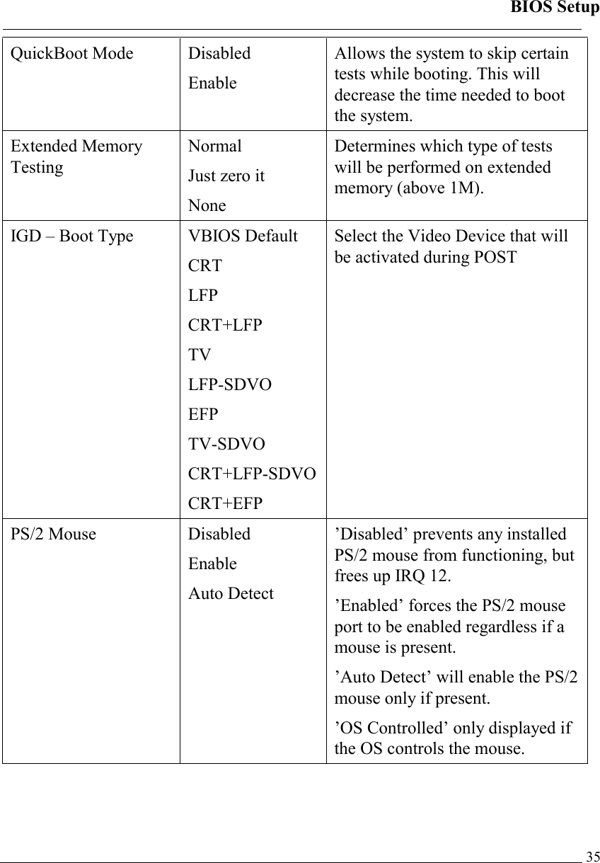
![BIOS Setup 34Advanced Menu Phoenix TrustedCore(tm) Setup Utility Main Advanced Security TPM State Boot Exit Item Specific Help Legacy USB Support: [Enabled] Summary screen: [Disabled] Boot-time Diagnostic Screen: [Enabled] QuickBoot Mode: [Enabled] Extended Memory Testing [Just zero it] IGD – Boot Type: [VBIOS Default] PS/2 Mouse [Auto Detect] PCI Express – Root Port 1: [Enabled] USB – Device 29, Function 7: [Enabled] • SIO SMC227 CONFGURATION Display the diagnostic screen during boot F1 Help ↑↓ Select Item –/+ Change Values F9 Setup Defaults Esc Exit ↔ Menu Enter Select ► Sub-Menu F10 Save and Exit Warning: Incorrect settings may cause system malfunction. To correct it, restore the Setup Defaults with <F9>. Advanced Menu Selections You can make the following selections on the Advanced Menu. Feature Options Description Legacy USB Support Disabled Enable Enable support for Legacy Universal Serial Bus Summary screen Disabled Enable Display system configuration on boot Boot-time Diagnostic Screen Disabled Enable Display the diagnostic screen during boot](https://usermanual.wiki/MilDef-Crete/RK886EX/User-Guide-818154-Page-42.png)
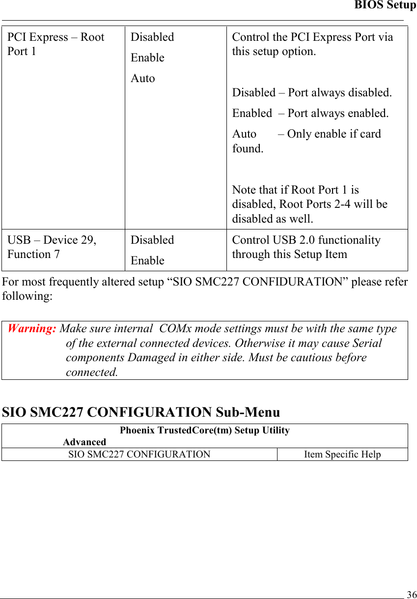
![BIOS Setup 37 COM1 port: [3F8-IRQ 4] COM1 mode: [RS232] COM2 port: [2F8-IRQ 3] COM2 mode: [RS232] COM3 port: [3E8-IRQ 10] COM3 mode: [RS232] COM4 port: [2E8-IRQ 5] COM4 mode: [RS232] Printer1: [378-IRQ 7] Printer1 mode: [Standatd] Configure COM1 using device options: [Disabled] No configuration [3F8-IRQ 4] Set the base I/O address for COM1 F1 Help ↑↓ Select Item –/+ Change Values F9 Setup Defaults Esc Exit ↔ Menu Enter Select ► Sub-Menu F10 Save and Exit SIO SMC227 CONFIGUARTION Sub-Menu Selections You can make the following selections on the SIO SMC227 CONFIGURATION sub menu. Feature Options Description COM1 port Disabled 3F8-IRQ 4 Configure COM1 using device options: [Disabled] No configuration [3F8-IRQ 4] Set the base I/O address for COM1](https://usermanual.wiki/MilDef-Crete/RK886EX/User-Guide-818154-Page-45.png)
![BIOS Setup 38COM1 mode RS485 RS422 RS232 TTL1 Configure UART mode options: [RS485]:External Device [RS422]:External Device [RS332]:External Device [TTL1]:Internal Device COM2 port Disabled 2F8-IRQ 3 Configure COM2 using device options: [Disabled] No configuration [2F8-IRQ 3] Set the base I/O address for COM2 COM2 mode RS485 RS422 RS232 TTL2 Configure UART mode options: [RS485]:External Device [RS422]:External Device [RS232]:External Device [TTL2]:Internal Device](https://usermanual.wiki/MilDef-Crete/RK886EX/User-Guide-818154-Page-46.png)
![BIOS Setup 39COM3 port Disabled 3E8-IRQ 10 Configure COM3 using device options: [Disabled] No configuration [3E8-IRQ 10] Set the base I/O address for COM3 COM3 mode RS485 RS422 RS232 TTL3 Configure UART mode options: [RS485]:External Device [RS422]:External Device [RS232]:External Device [TTL3]:Internal Device COM4 port Disabled 2E8-IRQ 5 Configure COM4 using device options: [Disabled] No configuration [2E8-IRQ 5] Set the base I/O address for COM4](https://usermanual.wiki/MilDef-Crete/RK886EX/User-Guide-818154-Page-47.png)
![BIOS Setup 40COM4 mode RS485 RS422 RS232 TTL4 Configure UART mode options: [RS485]:External Device [RS422]:External Device [RS232]:External Device [TTL4]:Internal Device Printer1 Disabled 378-IRQ 4 Configure Printer1 device options: [Disabled] No configuration [378-IRQ 7] Set the base I/O address for Printer1 Printer1 mode Standard ECP EPP Configure Printer1 mode options: Standard EPP ECP](https://usermanual.wiki/MilDef-Crete/RK886EX/User-Guide-818154-Page-48.png)
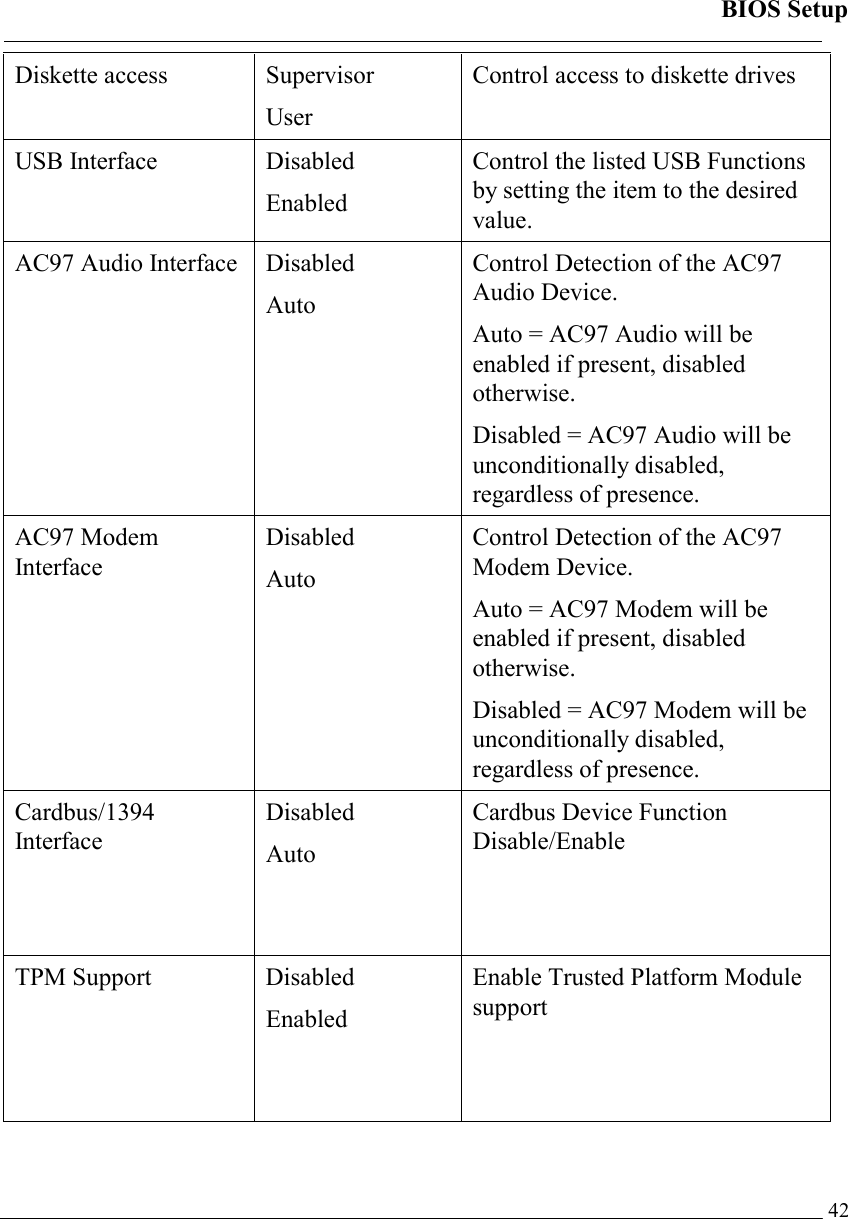
![BIOS Setup 41Security Menu Warning: If you forget user/supervisor password, the computer has to send back to manufacturer and replace EEPROM to make it work again. Phoenix TrustedCore(tm) Setup Utility Main Advanced Security TPM State Boot Exit Item Specific Help Processor Serial Number [Disabled] Fixed disk boot sector: [Normal] Diskette access: [Supervisor] USB Interface: [Enabled] AC97 Audio Interface: [Auto] AC97 Modem Interface: [Auto] Cardbus/1394 Interface [Auto] • RF Security Control: TPM Support [Disabled] Controls detection of Processor Serial No. System must be reset or restarted from power-on for settings to take effect.F1 Help ↑↓ Select Item –/+ Change Values F9 Setup Defaults Esc Exit ↔ Menu Enter Select ► Sub-Menu F10 Save and Exit Security Menu Selections You can make the following selections on the Security Menu. Feature Options Description Processor Serial Number Disabled Enabled Controls detection of Processor Serial No. System must be reset or restarted from power-on for settings to take effect. Fixed disk boot sector Normal Write Protect Write protects the boot sector on the hard disk to protect against viruses.](https://usermanual.wiki/MilDef-Crete/RK886EX/User-Guide-818154-Page-49.png)
![BIOS Setup 43For most frequently altered setup “RF Security Control” please refer following: RF Security Control Sub-Menu Phoenix TrustedCore(tm) Setup Utility Security RF Security Control: Item Specific Help Wireless Lan: [Disabled] Wireless Lan Control F1 Help ↑↓ Select Item –/+ Change Values F9 Setup Defaults Esc Exit ↔ Menu Enter Select ► Sub-Menu F10 Save and Exit RF Security Control Sub-Menu Selections You can make the following selections on the RF Security Control sub menu. Feature Options Description Wireless Lan Disabled Enabled Wireless Lan Control Enabled Wireless function](https://usermanual.wiki/MilDef-Crete/RK886EX/User-Guide-818154-Page-51.png)
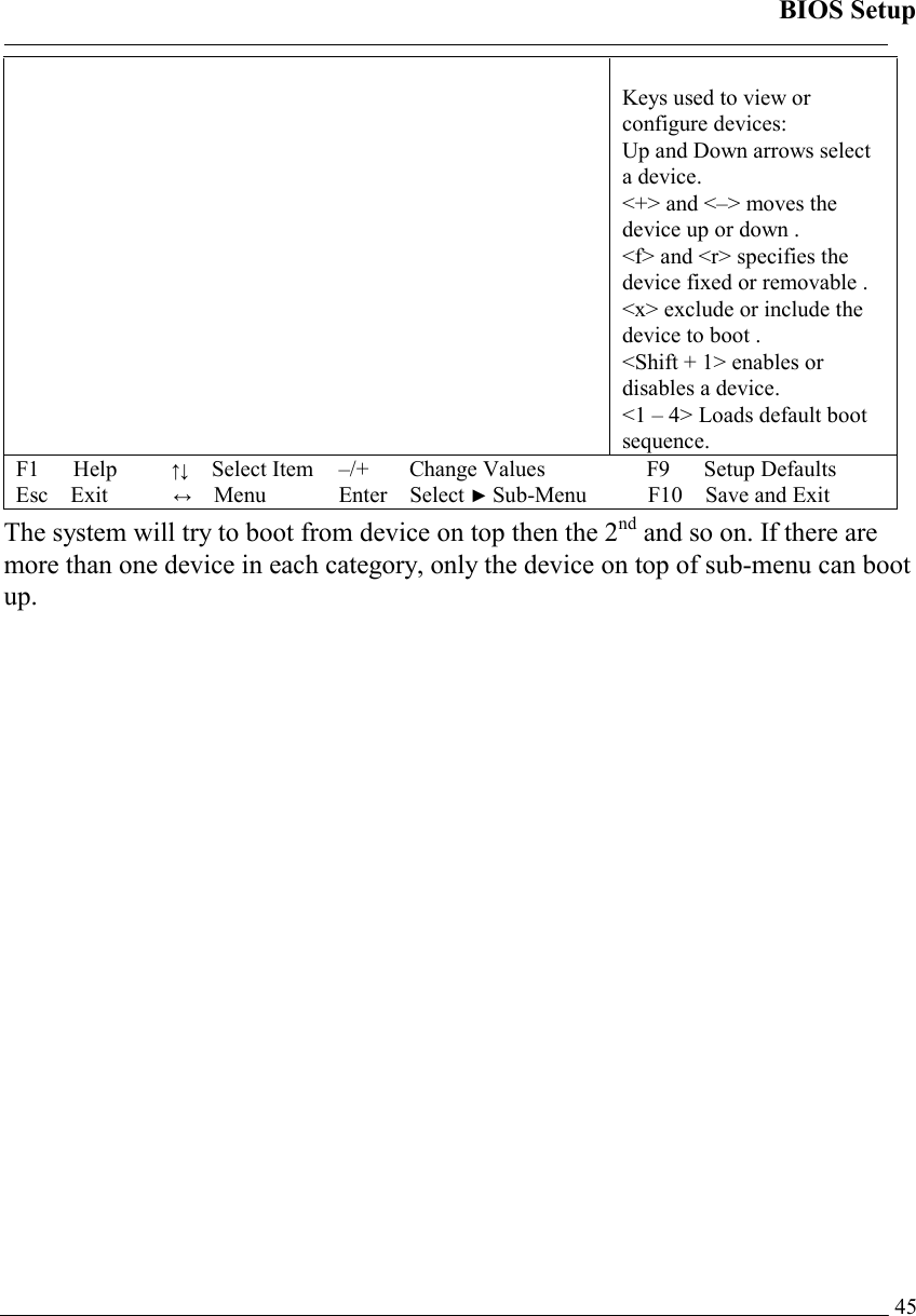
![BIOS Setup 44TPM State Menu Phoenix TrustedCore(tm) Setup Utility Main Advanced Security TPM State Boot Exit Item Specific Help Current TPM State: Enabled and Deactivated Change TPM State: [No Change] Change TPM State F1 Help ↑↓ Select Item –/+ Change Values F9 Setup Defaults Esc Exit ↔ Menu Enter Select ► Sub-Menu F10 Save and Exit TPM State Menu Selections You can make the following selections on the TPM State Menu. Feature Options Description Change TPM State No Change Enable & ActivateDeactivate & Disable Clear Change TPM State Boot Menu Phoenix TrustedCore(tm) Setup Utility Main Advanced Security TPM State Boot Exit Boot priority order: Item Specific Help](https://usermanual.wiki/MilDef-Crete/RK886EX/User-Guide-818154-Page-52.png)