MilDef Crete DT6 Tablet Computer User Manual
MilDef Crete Inc. Tablet Computer Users Manual
UserManual.wiki
>
MilDef Crete
>
DT6 User Manual
Users Manual
Navigation menu
Upload a User Manual
Namespaces
Wiki Guide
HTML
PDF
Info
Views
User Manual
Discussion / Help
Navigation

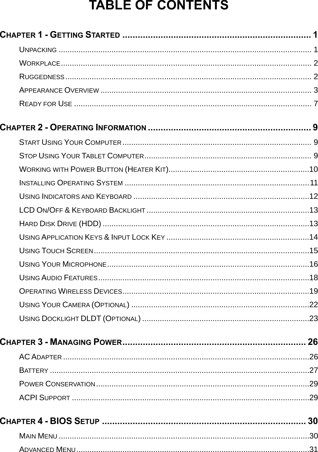
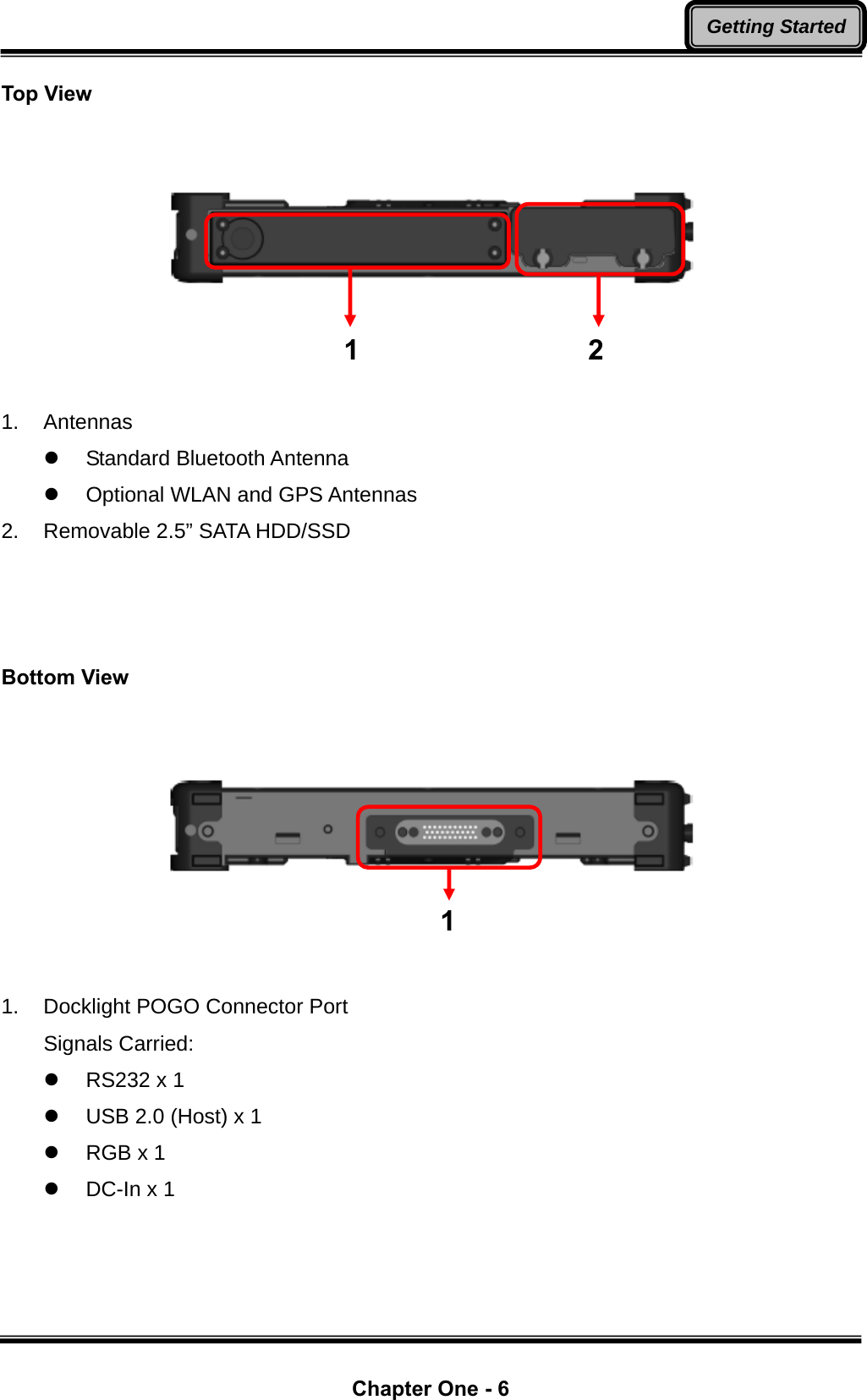
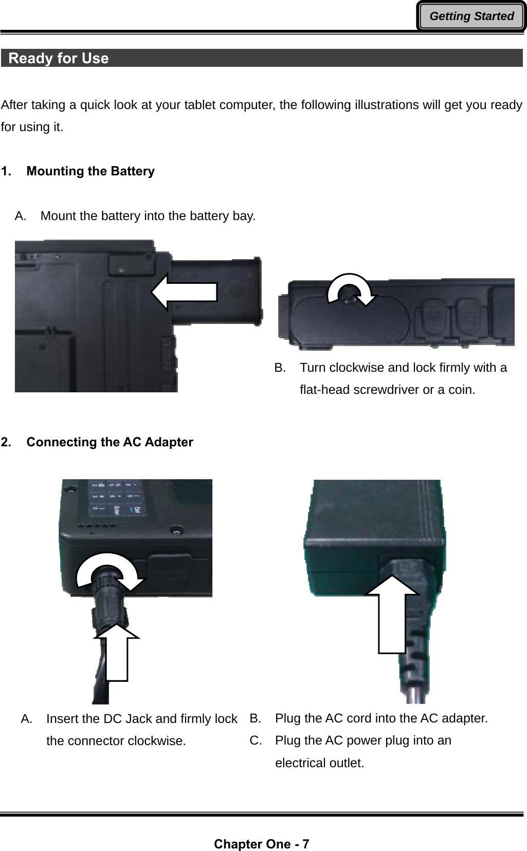
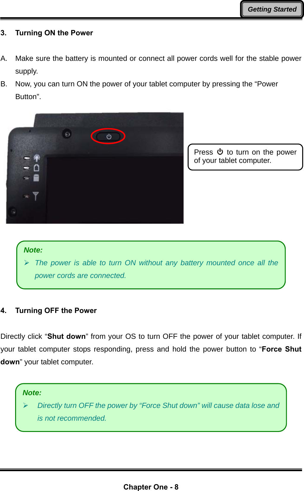
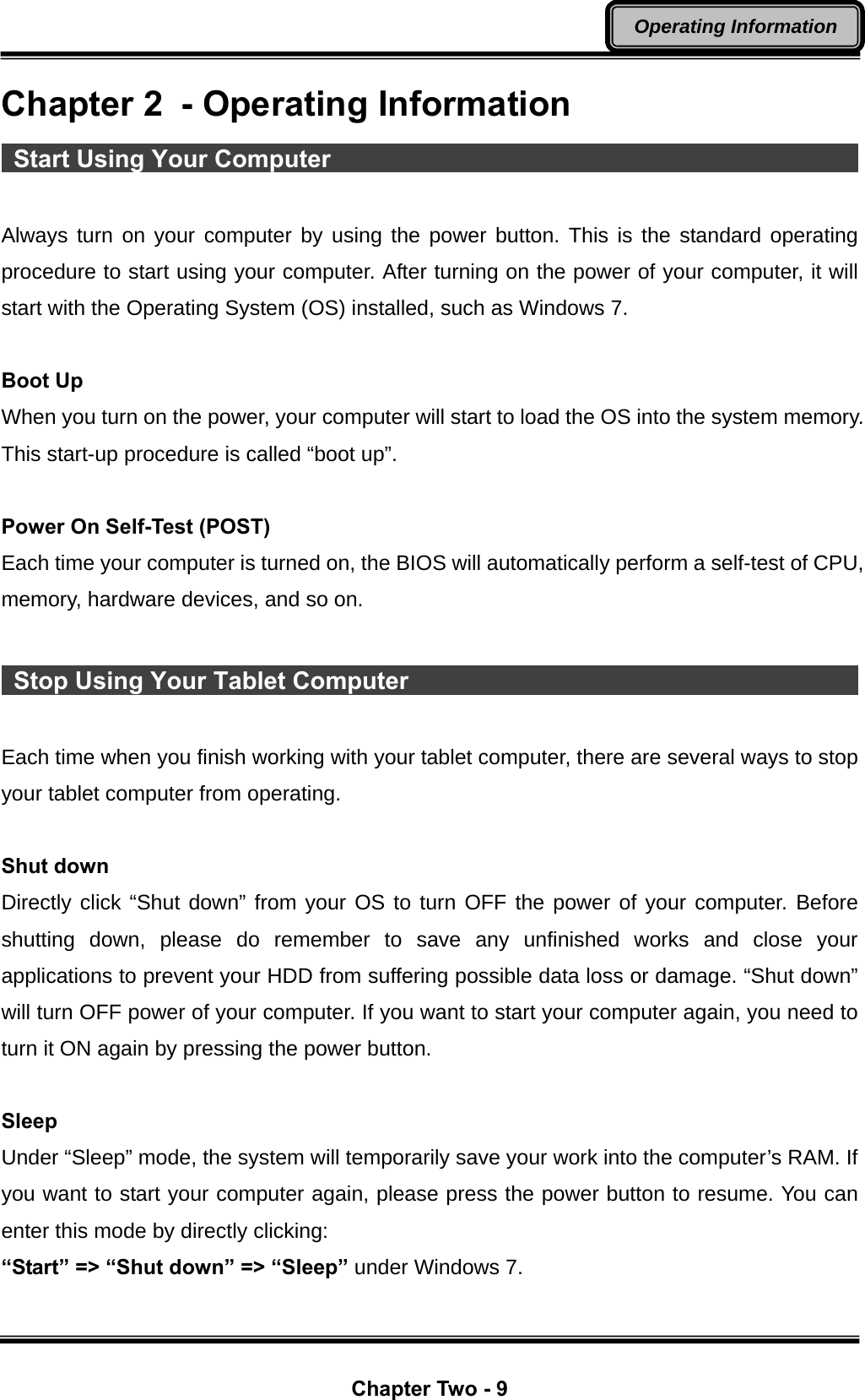
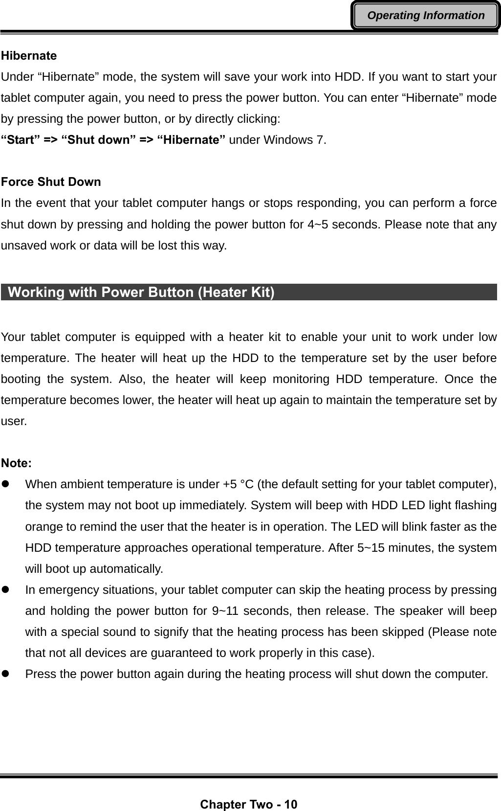
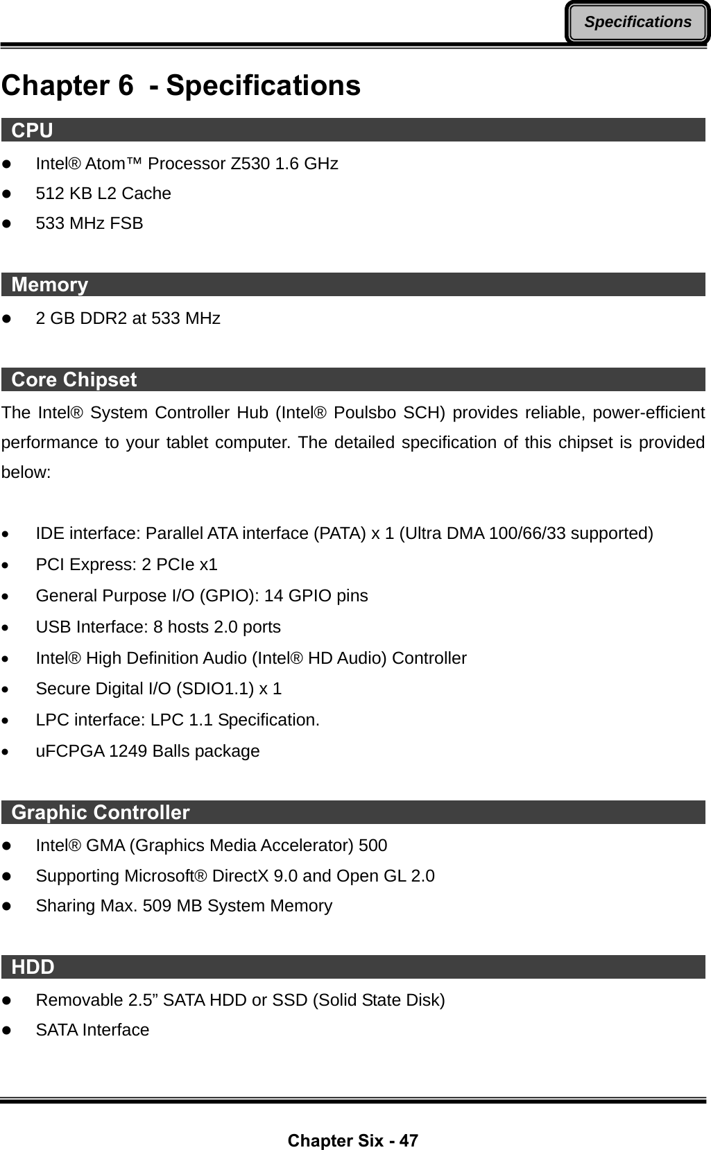
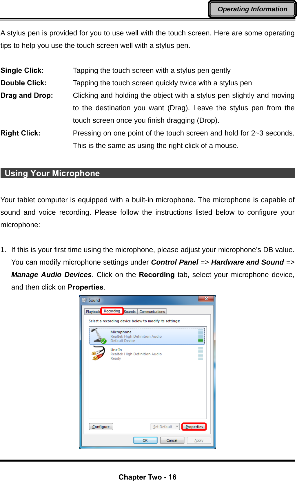
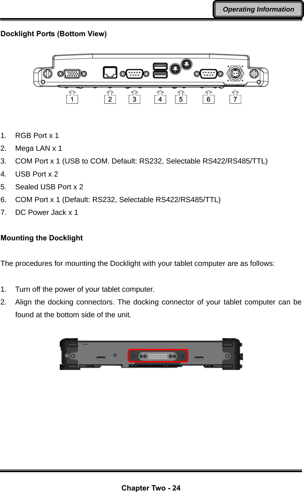
![Chapter Two - 12 Operating Information Using Indicators and Keyboard Your tablet computer is designed with a keyboard for easy and quick operations. Also, each LED indicator shows different meanings. Here are the descriptions for each button and LED indicator to help you use well with your tablet computer. LED Indicators Power Indicator: Green (Power); Flashing Red (S3: Standby); Flashing Green (Battery power is lower than 15% under S3 mode) Charger Indicator: Orange HDD Indicator (Dual LED): Green (HDD); Orange (Heater) Wireless Devices Indicator: Blue Input Lock Indicator: Red Caps Lock Indicator: Green Keyboard The 62 keys keyboard is a miniaturized keyboard designed to be functionally equivalent to a full size desktop keyboard. The keyboard layout is shown below: To perform 2nd layer combinational keystroke functions (keystroke functions printed in blue), press and hold [Fn], then press the corresponding key combinations.](https://usermanual.wiki/MilDef-Crete/DT6/User-Guide-1681930-Page-24.png)
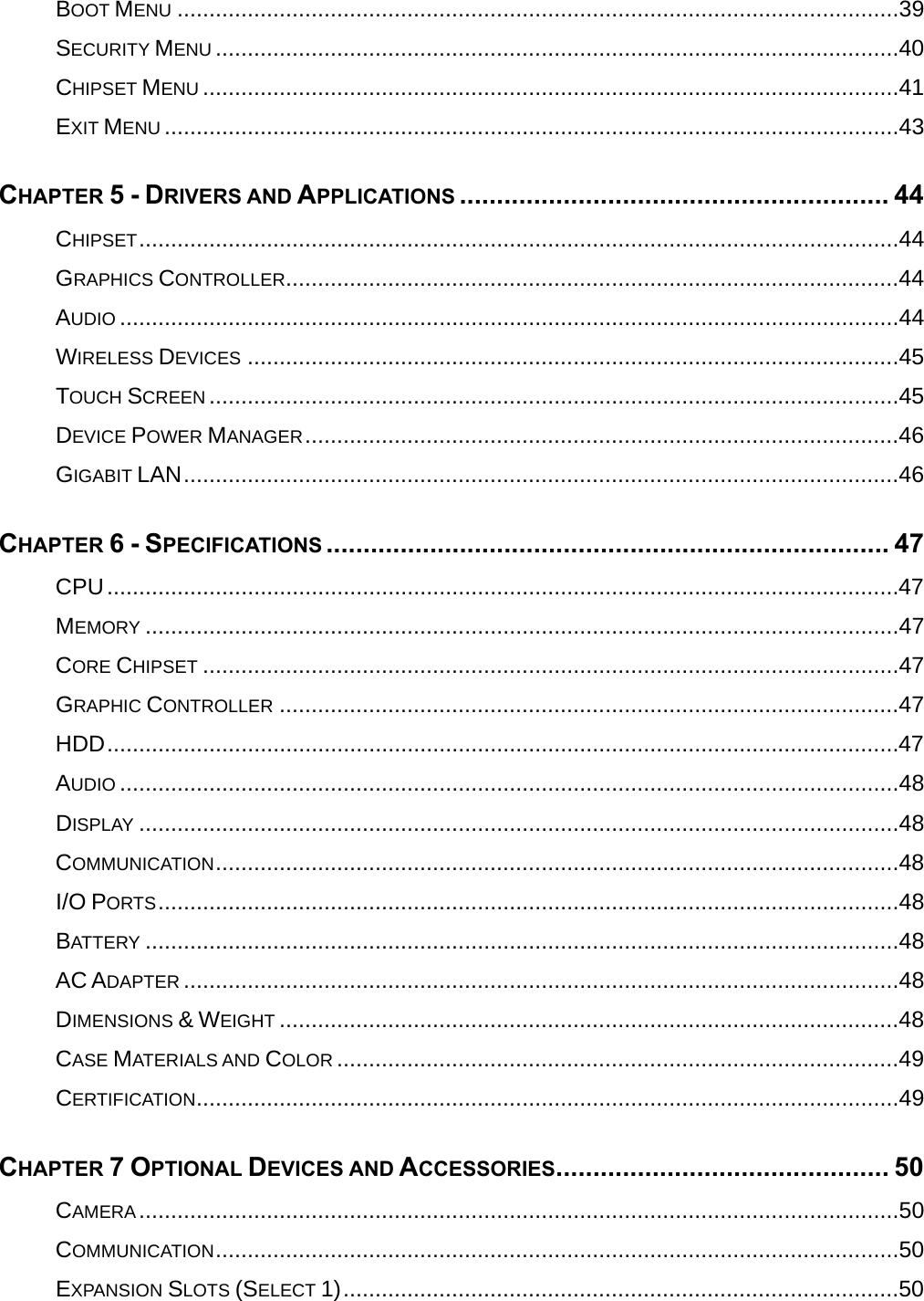
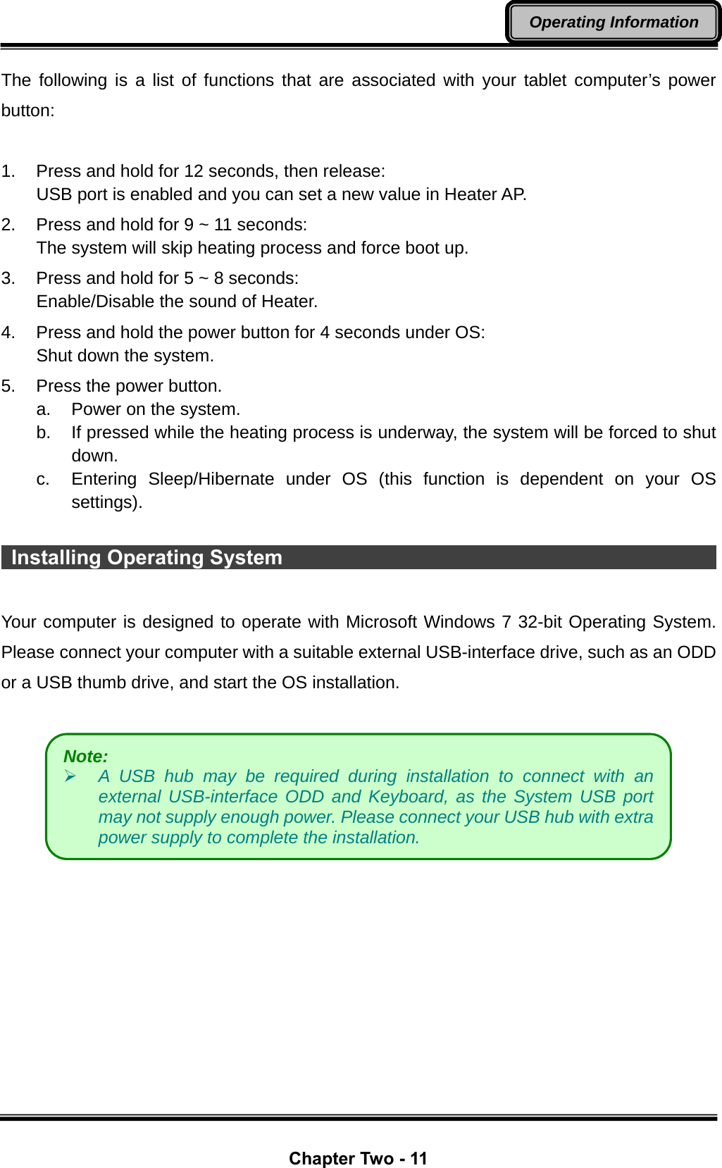
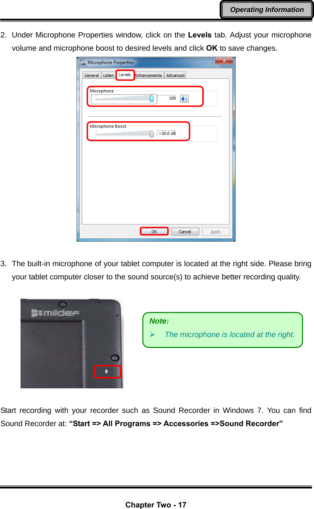
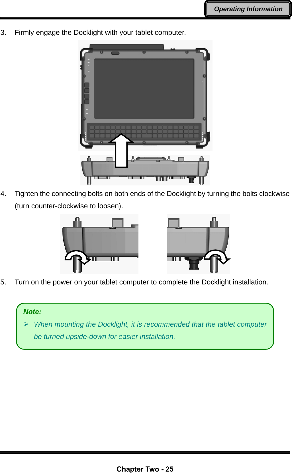
![Chapter Two - 13 Operating Information A list of useful combinational keystroke functions is provided below for operational reference: [Fn] + [V]: Turn your tablet computer’s LCD On/Off [Fn] + [B]: Turn your tablet computer’s keyboard backlight On/Off [Fn] + [↑]: Increase Audio Volume [Fn] + [↓]: Decrease Audio Volume [Fn] + [→]: Increase LCD brightness [Fn] + [←]: Decrease LCD brightness [Fn] + [Del]: Backspace Key [Fn] + [Tab]: Esc Key [Fn] + [F1 ~ F12]: Function Key F1 ~ F12 LCD On/Off & Keyboard Backlight To toggle LCD On/Off, press [Fn] + [V] key simultaneously to turn the LCD ON or OFF. To toggle keyboard backlight, Press [Fn] + [B] key simultaneously to turn the keyboard backlight ON or OFF. Hard Disk Drive (HDD) The Hard Disk Drive (HDD) / Solid State Drive (SSD)* is a 2.5” type / 9.5mm height standard SATA interface data storage device. The HDD (SSD) is removable. This design provides convenience and security. Please note that the drive can ONLY be removed when the power is OFF. Note: The key “AltGr”, which is a standard key in some language keyboard layouts, is removed due to space constraints. The function of the “AltGr” key is “Alt” + “Ctrl” key. If you need to access “AltGr”, please press “Alt” + “Ctrl” simultaneously.](https://usermanual.wiki/MilDef-Crete/DT6/User-Guide-1681930-Page-25.png)
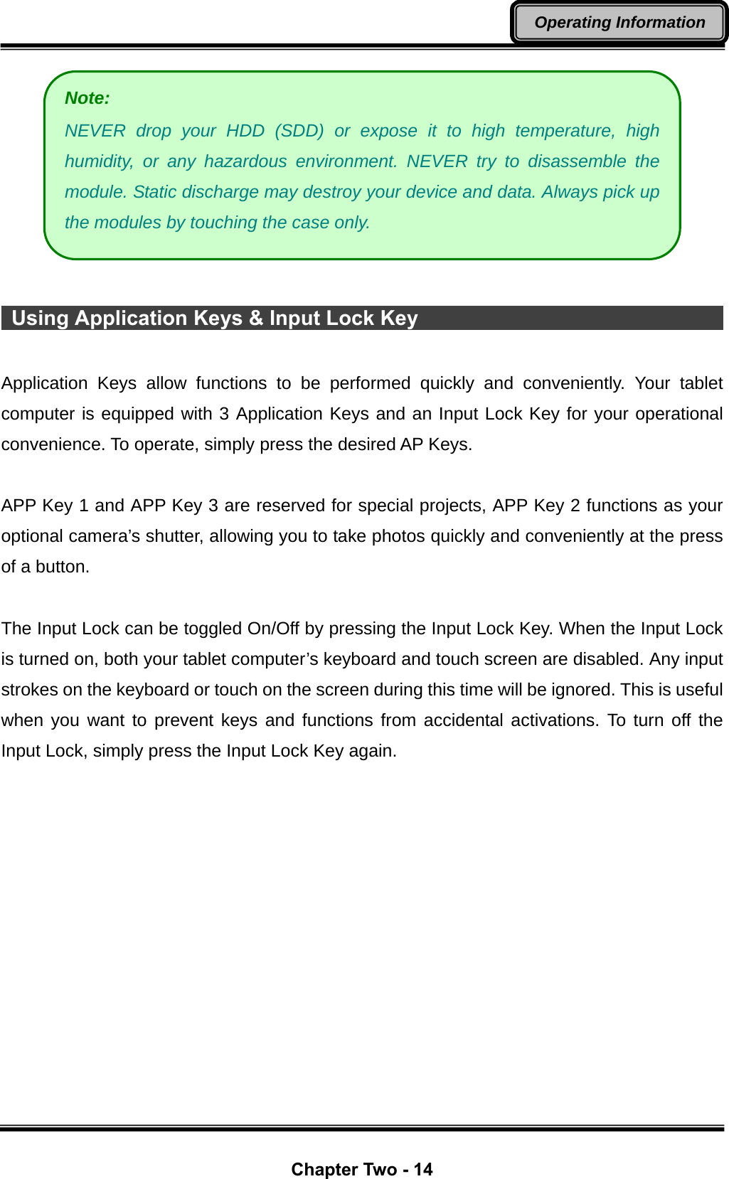
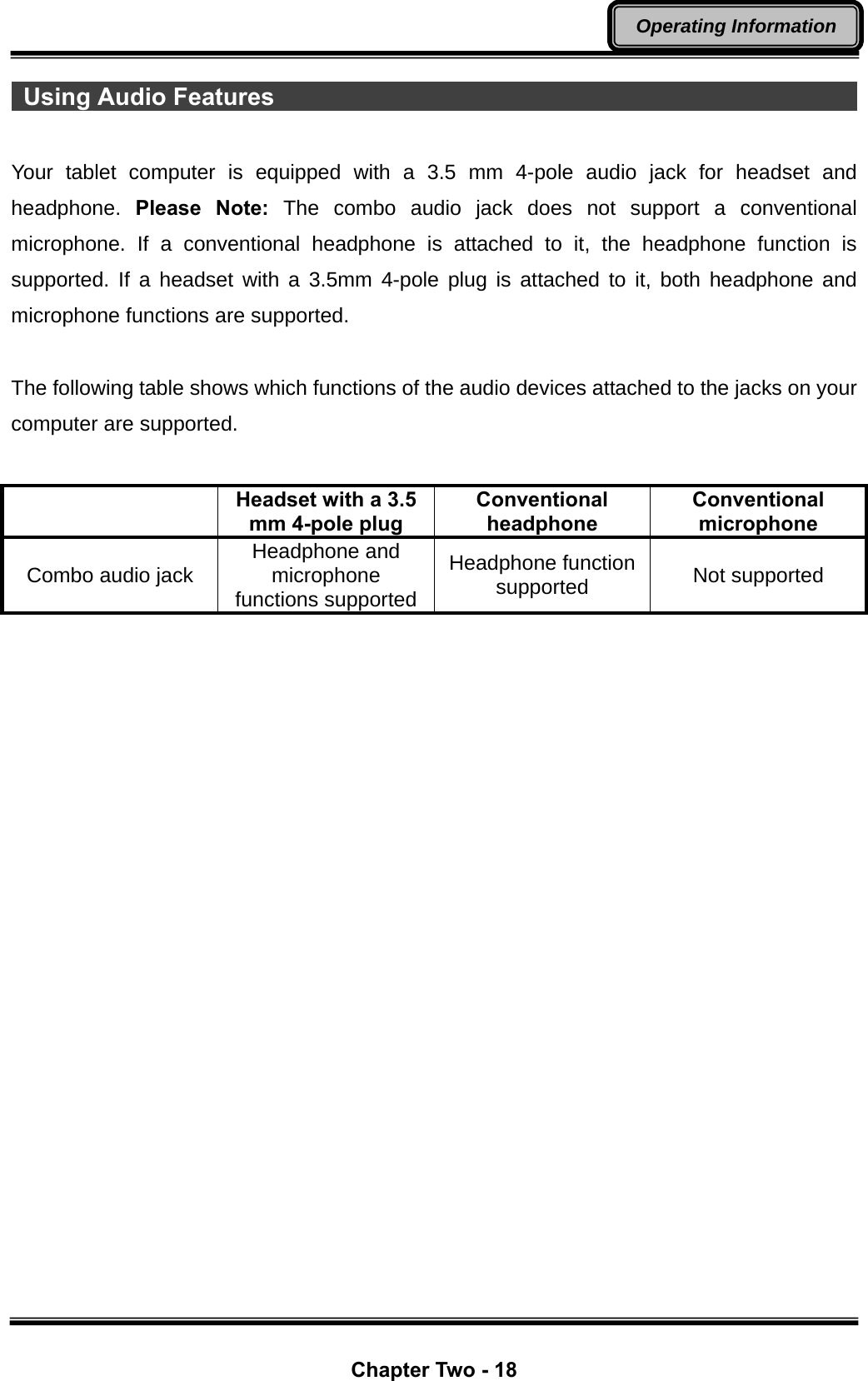
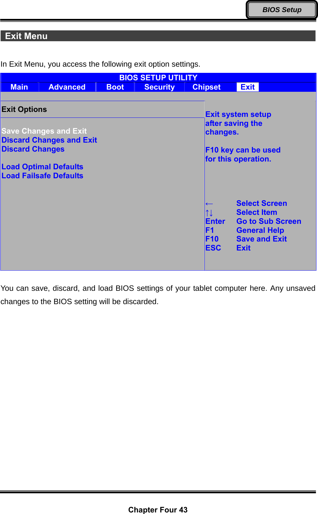
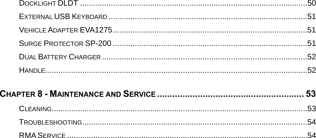
![Chapter Four 30 BIOS Setup Chapter 4 - BIOS Setup If you wish to change the BIOS settings of your tablet computer, turn on the power of your tablet computer and press “Del” key on your Mini Keyboard during boot-up sequence to enter the BIOS Setup Utility. Main Menu In Main Menu, you can access the System Overview as well as the operating instructions. BIOS SETUP UTILITY Main Advanced Boot Security Chipset Exit System Overview AMIBIOS Version :08.00.15 Build Date :11/03/11 ID :1AAAA000 Processor Intel(R) Atom(TM) CPU Z530 @ 1.60GHz Speed :1600MHz Count :1 System Memory Size :2039MB System Time [16:15:25] System Date [Tue 11/29/2011] CMC Lo-Module: OD2.026x, Hi-Module:OD2.018x Use [Enter], [TAB] or [SHIFT-TAB] to select a field. Use [+] or [-] to configure system Time. ← Select Screen ↑↓ Select Item +- Change Field Tab Select Field F1 General Help F10 Save and Exit ESC Exit Main Menu Selections You can make the following changes under the Main Menu Selections. Feature Options Description System Time HH:MM:SS Set the system time Hour, Minute, Second. System Date MM/DD/YYYY Set the system date Month, Day, and Year.](https://usermanual.wiki/MilDef-Crete/DT6/User-Guide-1681930-Page-42.png)
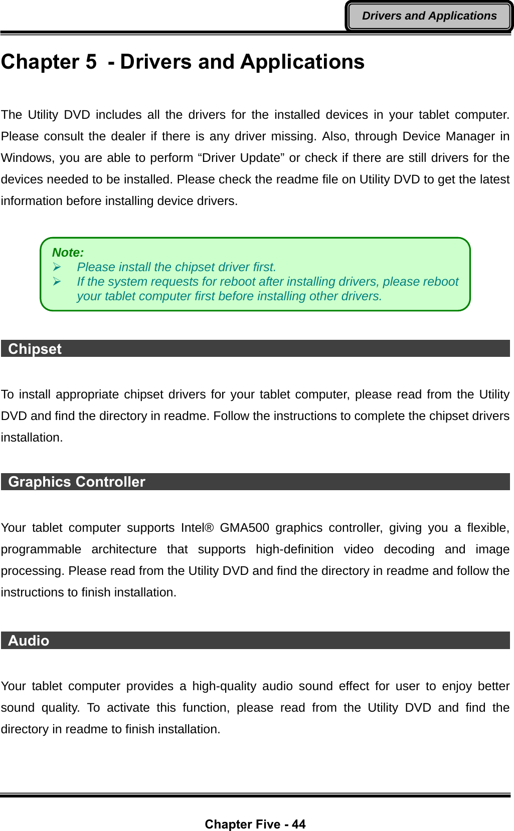
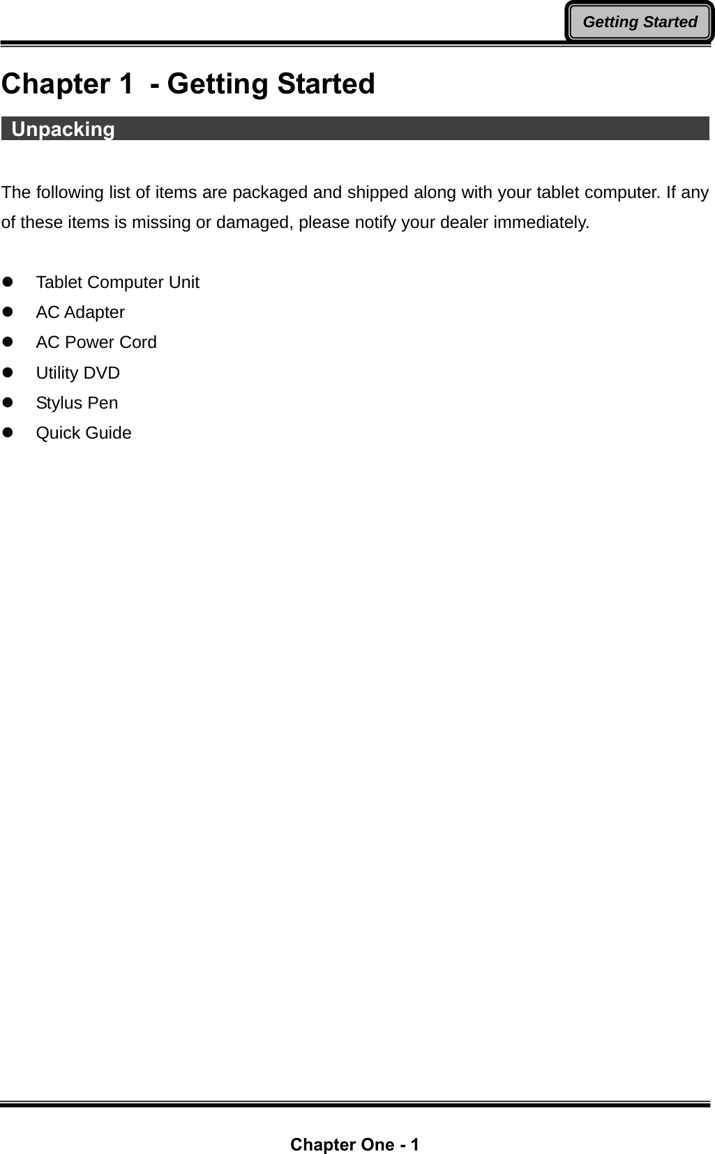
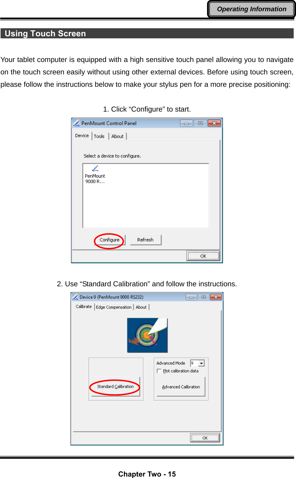
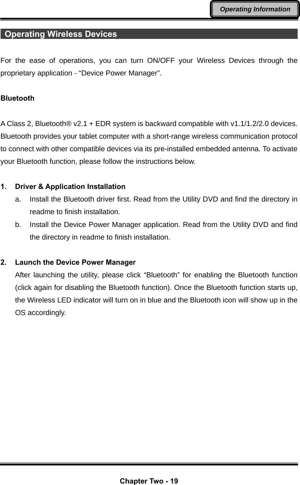
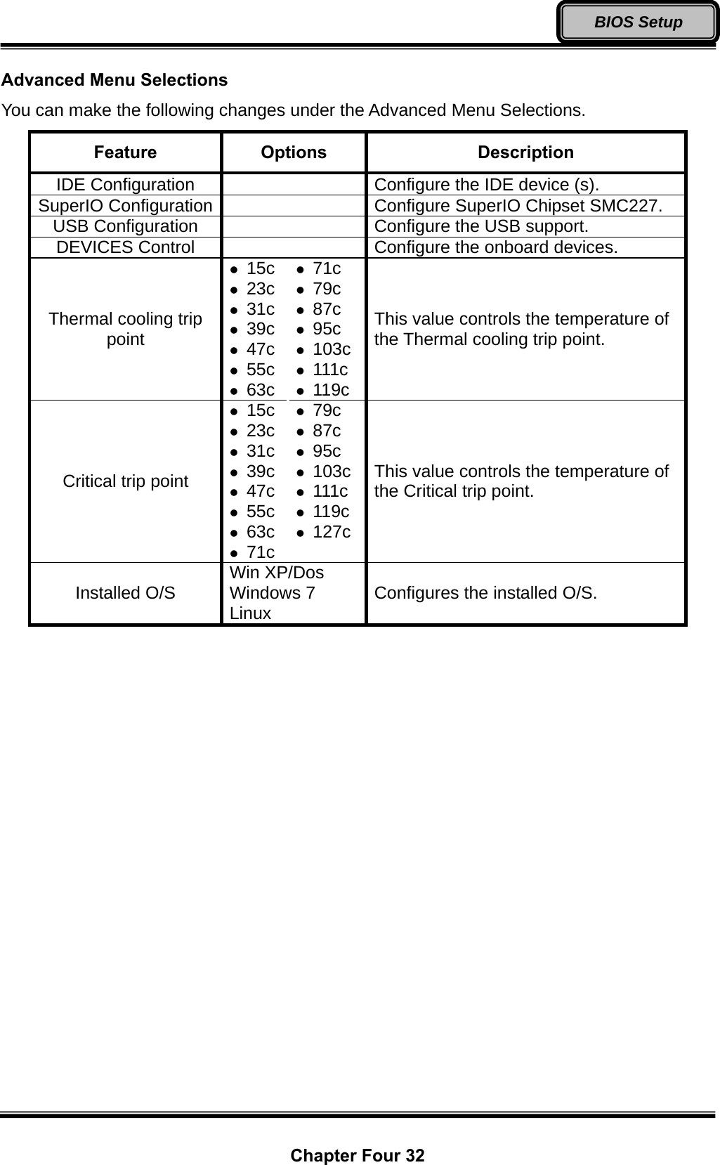
![Chapter Four 31 BIOS Setup Advanced Menu In Advanced Menu, you can access the following advanced settings. BIOS SETUP UTILITY Main Advanced Boot Security Chipset Exit Advanced Settings Warning: Setting wrong values in below sections may cause system to malfunction. ► IDE Configuration ► SuperIO Configuration ► USB Configuration ► DEVICES Control Thermal cooling trip point [79C] Critical trip point [103C] Installed O/S [Windows 7] Configure the IDE device (s). ← Select Screen ↑↓ Select Item Enter Go to Sub ScreenF1 General Help F10 Save and Exit ESC Exit](https://usermanual.wiki/MilDef-Crete/DT6/User-Guide-1681930-Page-43.png)
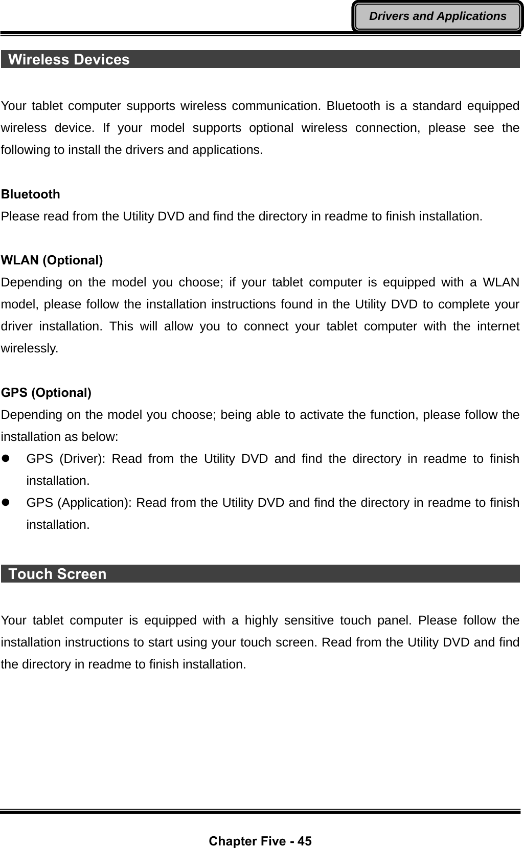
![Chapter Four 33 BIOS Setup IDE Configuration Sub-Menu In IDE Configuration Sub-Menu, you can change the configuration of your IDE devices. BIOS SETUP UTILITY Main Advanced Boot Security Chipset Exit IDE Configuration Options ATA/IDE Configuration [Compatible] ► Primary IDE Master : [Hard Disk] ► Primary IDE Slave : [Not Detected] Hard Disk Write Protect [Disabled] IDE Detect Time Out (Sec) [35] ATA(PI) 80Pin Cable Detection [Device] Disabled Compatible ← Select Screen ↑↓ Select Item +- Change Option F1 General Help F10 Save and Exit ESC Exit IDE Configuration Sub-Menu Selections You can make the following changes under the IDE Configuration Sub-Menu Selections. Feature Options Description ATA/IDE Configuration Disabled Compatible Enable or disable ATA/IDE compatibility. Primary IDE Master Configure the Primary IDE Master device. Primary IDE Slave Configure the Primary IDE Slave device. Hard Disk Write Protect Disabled Enabled Disable/Enable device write protection. This will be effective only if device is accessed through BIOS.IDE Detect Time Out (Sec) z 0 z 5 z 10 z 15 z 20 z 25 z 30 z 35 Select the time out value for detecting ATA/ATAPI device (s). ATA(PI) 80Pin Cable Detection Host & Device Host Device Configure whether Host, Device, or Host & Device should be allowed to detect the type of IDE cable used.](https://usermanual.wiki/MilDef-Crete/DT6/User-Guide-1681930-Page-45.png)
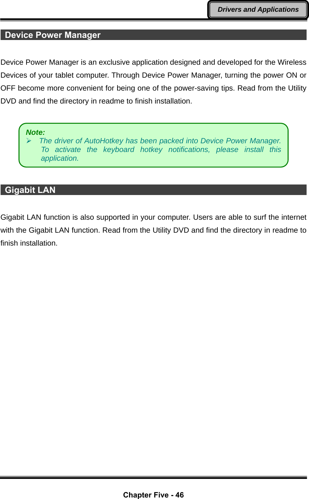
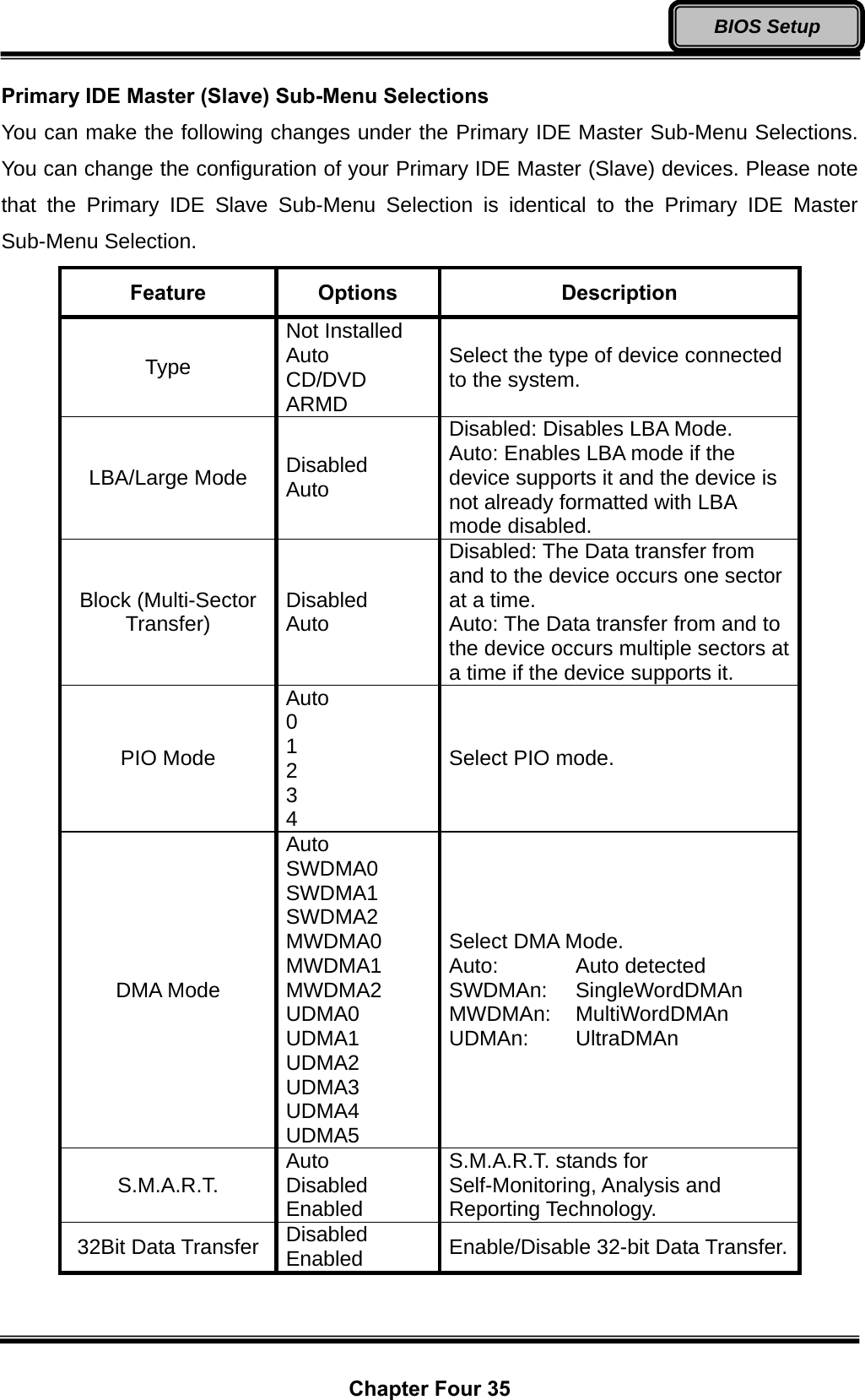
![Chapter Four 34 BIOS Setup Primary IDE Master (Slave) Sub-Menu In Primary IDE Master (Slave) Sub-Menu, you can change specific settings, such as mode and rate of data transfer, of your IDE devices. BIOS SETUP UTILITY Main Advanced Boot Security Chipset Exit Primary IDE Master Device :Hard Disk Vendor :Toshiba MK5065GSX Size :500.1GB LBA Mode :Supported Block Mode :16 Sectors PIO Mode :4 Async DMA :MultiWord DMA-2 Ultra DMA :Ultra DMA-5 S.M.A.R.T :Supported Type [Auto] LBA/Large Mode [Auto] Block (Multi-Sector Transfer) [Auto] PIO Mode [Auto] DMA Mode [Auto] S.M.A.R.T. [Auto] 32Bit Data Transfer [Auto] Select the type of device connected to the system. ← Select Screen ↑↓ Select Item +- Change Option F1 General Help F10 Save and Exit ESC Exit](https://usermanual.wiki/MilDef-Crete/DT6/User-Guide-1681930-Page-46.png)
![Chapter Four 36 BIOS Setup Super IO Configuration Sub-Menu In Super IO Configuration Sub-Menu, you can change the configuration of your COM ports BIOS SETUP UTILITY Main Advanced Boot Security Chipset Exit Configure SMC227 Super IO Chipset COM 1 Mode Setting [RS232] COM 1 Mode Setting [RS232] mode options: [RS232] : External Device [TTL1] : Internal Device [RS422] : External Device [RS485] : External Device ← Select Screen ↑↓ Select Item +- Change Option F1 General Help F10 Save and Exit ESC Exit Super IO Configuration Sub-Menu Selections You can make the following changes under the Super IO Configuration Sub-Menu Selections. Feature Options Description COM 1 Mode Setting RS232 RS422 RS485 TTL1 Configure the mode of operation for COM 1 port. COM 2 Mode Setting RS232 RS422 RS485 TTL1 Configure the mode of operation for COM 2 port.](https://usermanual.wiki/MilDef-Crete/DT6/User-Guide-1681930-Page-48.png)
![Chapter Four 37 BIOS Setup USB Configuration Sub-Menu In USB Configuration Sub-Menu, you can change the configuration of your USB module and devices. BIOS SETUP UTILITY Main Advanced Boot Security Chipset Exit USB Configuration Module Version – 2.23.4-13.4 USB Devices Enabled : 2 Hubs Legacy USB Support [Enabled] USB 2.0 Controller Mode [HiSpeed] BIOS EHCI Hand-Off [Enabled] Enable support for legacy USB. AUTO option disables legacy support if no USB devices are connected. ← Select Screen ↑↓ Select Item +- Change Option F1 General Help F10 Save and Exit ESC Exit USB Configuration Sub-Menu Selections You can make the following changes under the USB Configuration Sub-Menu Selections. Feature Options Description Legacy USB Support Disabled Enabled Auto Enable support for legacy USB. AUTO option disables legacy support if no USB devices are connected. USB 2.0 Controller Mode FullSpeed HiSpeed Configure the USB 2.0 controller in HiSpeed (480Mbps) or FullSpeed (12Mbps). BIOS EHCI Hand-Off Disabled Enabled This is a workaround for OSes without EHCI hand-off support. The EHCI ownership change should claim by EHCI driver.](https://usermanual.wiki/MilDef-Crete/DT6/User-Guide-1681930-Page-49.png)
![Chapter Four 38 BIOS Setup DEVICES Control Sub-Menu In DEVICES Control Sub-Menu, you can change the configuration of your onboard devices, such as WLAN, GPS, Bluetooth, or Camera. BIOS SETUP UTILITY Main Advanced Boot Security Chipset Exit Options Wireless Lan [OFF] GPS [OFF] BLUETOOTH [ON] CAMERA [OFF] OFF ON ← Select Screen ↑↓ Select Item +- Change Option F1 General Help F10 Save and Exit ESC Exit DEVICES Control Sub-Menu Selections You can make the following changes under the DEVICES Control Sub-Menu Selections. Feature Options Description Wireless Lan OFF ON Toggle Wireless Lan device ON/OFF. GPS OFF ON Toggle GPS device ON/OFF. BLUETOOTH OFF ON Toggle Bluetooth device ON/OFF. CAMERA OFF ON Toggle Camera device ON/OFF.](https://usermanual.wiki/MilDef-Crete/DT6/User-Guide-1681930-Page-50.png)
![Chapter Four 39 BIOS Setup Boot Menu In Boot Menu, you can access the following boot settings. BIOS SETUP UTILITY Main Advanced Boot Security Chipset Exit Boot Settings 1st Boot Device [USB] 2nd Boot Device [SATA: PM-TOSHIBA MK]3rd Boot Device [CD/DVD] 4th Boot Device [Removable Dev.] 5th Boot Device [Network: Realtek Bo] Specifies the boot sequence from the available devices. A device enclosed in parenthesis has been disabled in the corresponding type menu. ← Select Screen ↑↓ Select Item +- Change Option F1 General Help F10 Save and Exit ESC Exit Your tablet computer will attempt to boot from the available boot devices in sequence. This feature is useful when you wish to boot your tablet computer from alternative boot devices for troubleshooting, maintenance or service.](https://usermanual.wiki/MilDef-Crete/DT6/User-Guide-1681930-Page-51.png)
![Chapter Four 40 BIOS Setup Security Menu In Security Menu, you can access the following security settings. BIOS SETUP UTILITY Main Advanced Boot Security Chipset Exit Security Settings Supervisor Password :Not Installed User Password :Not Installed Change Supervisor Password Change User Password Boot Sector Virus Protection [Disabled] Install or Change the password. ← Select Screen ↑↓ Select Item Enter Change F1 General Help F10 Save and Exit ESC Exit You can setup Supervisor Password, User Password, as well as Disable/Enable Boot Sector Virus Protection. Feature Options Description Change Supervisor Password Supervisor Password controls access to the BIOS setup utility. Change User Password User Password controls access to boot the tablet computer. Boot Sector Virus Protector Disabled Enabled Enable/Disable Boot Sector Virus Protection.](https://usermanual.wiki/MilDef-Crete/DT6/User-Guide-1681930-Page-52.png)
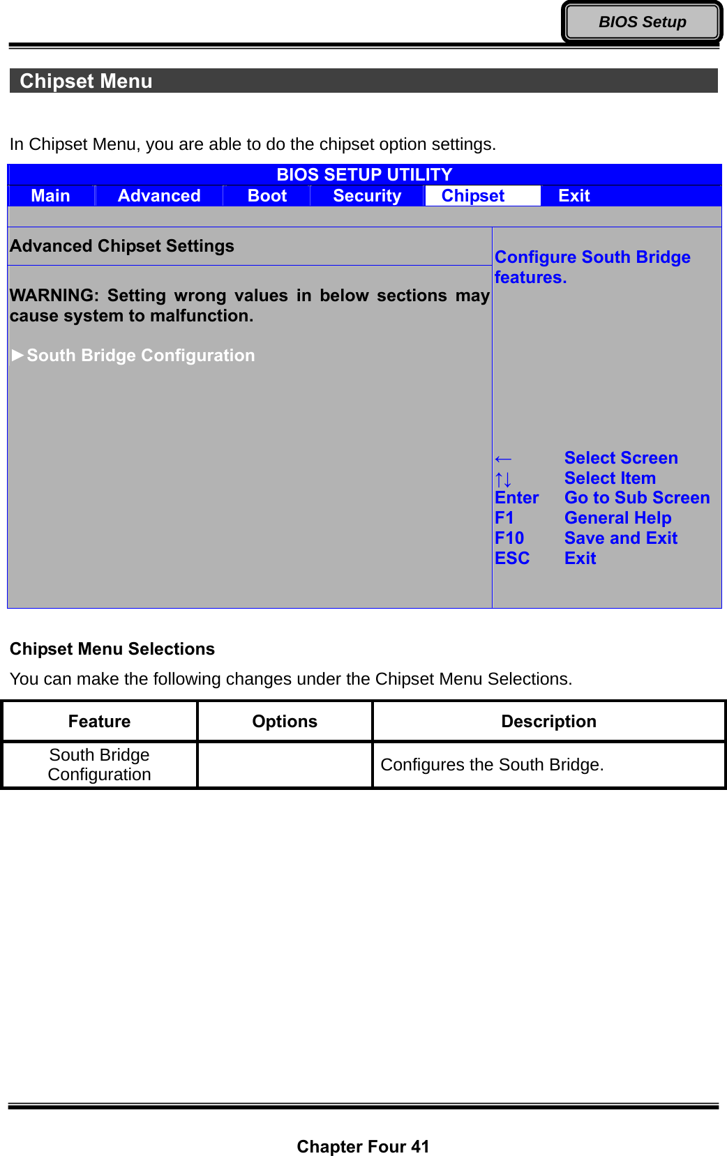
![Chapter Four 42 BIOS Setup South Bridge Configuration Sub-Menu In South Bridge Configuration Sub-Menu, you can change the South Bridge Configuration. BIOS SETUP UTILITY Main Advanced Boot Security Chipset Exit South Bridge Configuration Options USB Client Controller [Disabled] Enabled Disabled ← Select Screen ↑↓ Select Item +- Change Option F1 General Help F10 Save and Exit ESC Exit South Bridge Configuration Sub-Menu Selections You can make the following changes under the DEVICES Control Sub-Menu Selections. Feature Options Description USB Client Controller Disabled Enabled Enable or Disable USB Client Controller.](https://usermanual.wiki/MilDef-Crete/DT6/User-Guide-1681930-Page-54.png)